

DeVilbiss Cobra 2 Operation Manual
EN
SB-E-2-CBA2
Operation Manual
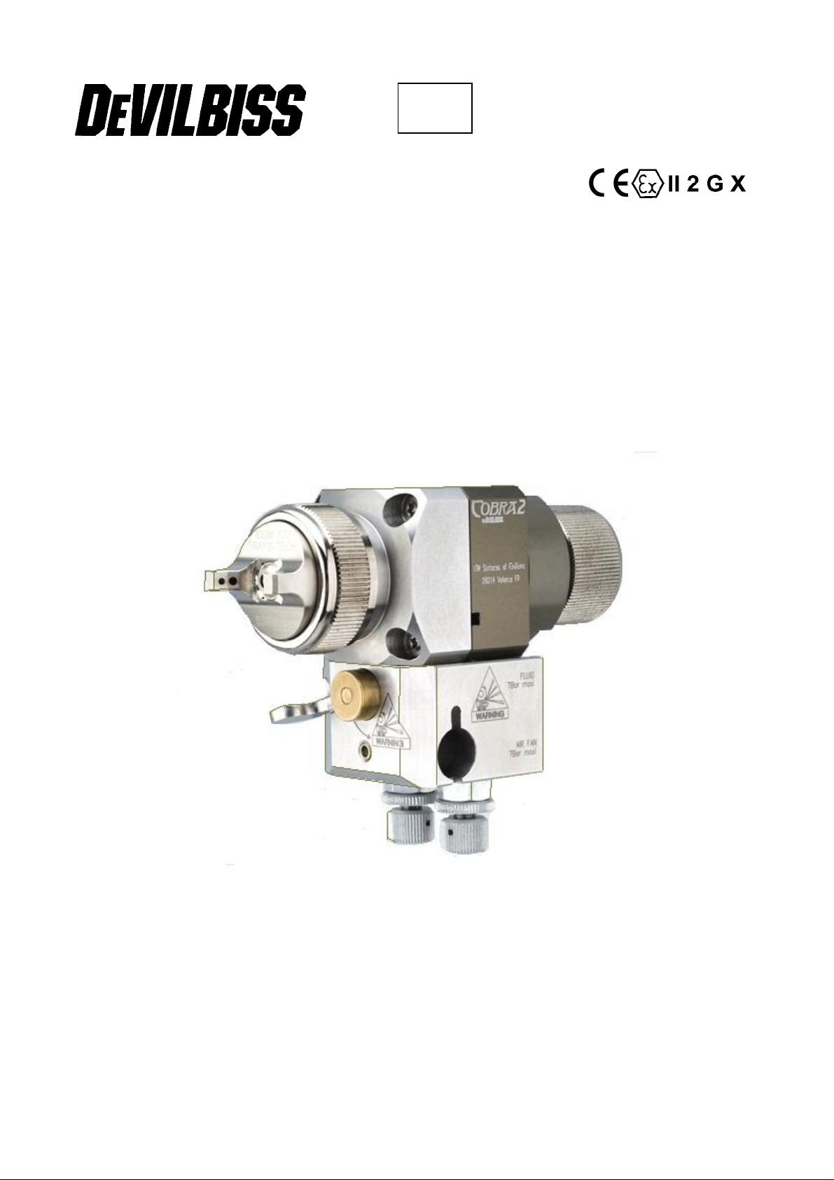
Cobra 2 – Automatic Spray Gun
ISS.09
1
Operation Manual
Cobra 2 Automatic Spraygun
Important
Read and follow all instructions and Safety Precautions before using this
equipment
CHARACTERISTICS
This automatic spray gun complies to ATEX regulations 94/9/EC, protection level II 2 G X, suitable to
use in Zones 1 & 2.
This Cobra 2 is a production spray gun suitable for use with automatic and semi-automatic machines
in conventional, HVLP or Trans-Tech applications.
Cobra 2 has a ¼ turn Quick detachable device, so to reduce maintenance & set up time (SMED).
To handle a wide range of coating materials the fluid passages are manufactured from high grade
stainless steel.
This spray gun is supplied with an indexed air cap. You can leave your air cap capable of free
rotation by removing the indexed plastic ring which is located by 2 pins on the air cap.
Pressure feed material supply can be re-circulating or direct.
The needle adjustment knob has 18 ratchet positions, allows fine and accurate fluid flow control.
SPECIFICATIONS & MATERIALS OF CONSTRUCTION
Thread Pressure
Fluid inlet & recirculation “P”
Air inlet (Atom+Fan) “A” “F”
Cylinder/trigger “C”
Maximum temperature in use
Spray gun weight
Gun body
Tip / Needle / Spray head/ Base plate
1/8 BSP
1/8 BSP
1/8 BSP
40° C
950 g
Aluminium hard anodized
Stainless steel 303
Max 7 Bar
Max 7 Bar
4 to 7 bar
EC Declaration of Conformity
We, ITW Finishing UK, Ringwood Rd, Bournemouth, Dorset, BH11 9LH, UK, as the
manufacturer of the Spray gun model COBRA , declare, under our sole responsibility that the
equipment to which this document relates is in conformity with the following standards or other
normative documents:
BS EN 292-1 PARTS 1 & 2: 1991, BS EN 1953: 1999; and thereby conform to the protection
requirements of Council Directive 98/37/EEC relating to Machinery Safety Directive, and;
EN 13463-1:2001, council Directive 94/9/EC relating to Equipment and Protective Systems
intended for use in Potentially Explosive Atmospheres protection level II 2 G X.
B. Holt, General Manager 24th April 2007
ITW Finishing Systems and Products reserve the right to modify equipment specification without prior notice.
2
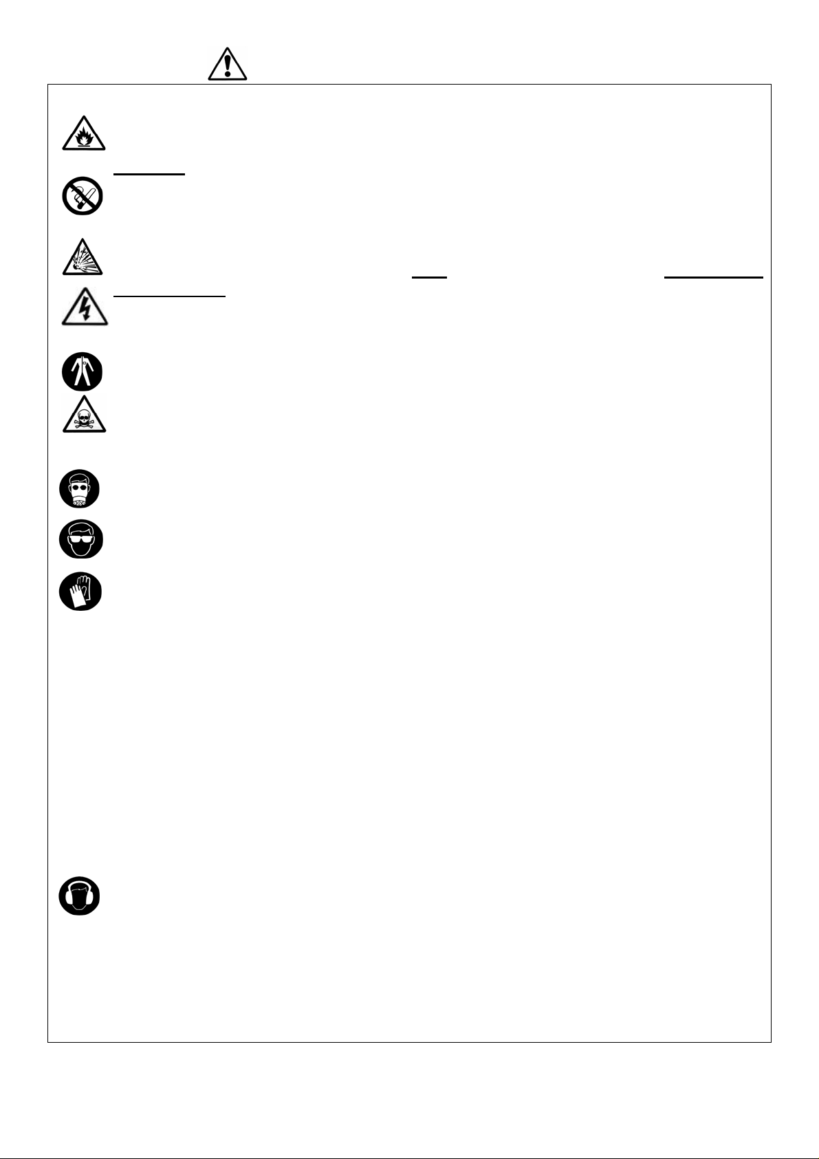
SAFETY WARNINGS
Fire and explosion
Solvents and coating materials can be highly flammable or combustible when sprayed.
ALWAYS refer to the coating material supplier’s instructions and COSHH sheets
before using this equipment.
Users must comply with all local and national codes of practice and insurance company
requirements governing ventilation, fire precautions, operation and house-keeping of
working areas.
This equipment, as supplied, is NOT suitable for use with Halogenated
Hydrocarbons.
Static electricity can be generated by fluid and/or air passing through hoses, by the
spraying process and by cleaning non- conductive parts with cloths. To prevent ignition
sources from static discharges, earth continuity must be maintained to the spray gun and
other metallic equipment used. It is essential to use conductive air and/or fluid hoses.
Personal Protective Equipment
Toxic vapours – When sprayed, certain materials may be poisonous, create irritation or
are otherwise harmful to health. Always read all labels, safety data sheets and follow any
recommendations for the material before spraying. If in doubt, contact your material
supplier.
The use of respiratory protective equipment is recommended at all times. The type of
equipment must be compatible with the material being sprayed.
Always wear eye protection when spraying or cleaning the spray gun.
Gloves must be worn when spraying or cleaning the equipment.
Training – Personnel should be given adequate training in the safe use of spraying equipment.
Misuse
Never aim a spray gun at any part of the body.
Never exceed the max. Recommended safe working pressure for the equipment.
The fitting of non-recommended or non-original spares may create hazards.
Before cleaning or maintenance, all pressure must be isolated and relieved from the equipment.
The product should be cleaned using a gun-washing machine. However, this equipment should
not be left inside gun-washing machines for prolonged periods of time.
Noise Levels
The A-weighted sound level of spray guns may exceed 85 dB (A) depending on the setup being used. Details of actual noise levels are available on request. It is recommended
that ear protection is worn at all times when spraying.
Operating
Spray equipment using high pressures may be subject to recoil forces. Under certain
circumstances, such forces could result in repetitive strain injury to the operator.
3

LIST OF SPARE PARTS
Rep Ref Description Qty
1 SP-100-xxx-K
SP-247S-xx-K
2
SP-200S-xx-K
SP-259S-xx-K
4 SPA-112
5 SPA-27-K5
6 S-14192-K4
SPA-50
8
SPA-50U
8a SPA-51
SPA-86-K
9
SPA-86-K10
10 SPA-29X-K4
11 SPA-53-K10
12 SPA-1-CBA2
12a SPA-52
12b S-28223X-K4
13 AGG-403
14 S-28220X-K2
15 SPA-60X-K
15b SPA-62-K2
15c S-28224X-K4
15d S-28225X-K2
16 S-28219X-K4
17 SPA-13
SPA-320-xx-K
18
SPA-320P-xx-K
SPA-320N-xx-K
19 SPA-3
20
SPA-KK-1
21
22 SPA-31
23 SPA-37
24 SPA-49
25 SPA-4
26* SPA-7-K
27 SPA-55-K
28 SPA-56-K
28a SPA-59
29* SS-659-CD
30* AGGS-33
31 S-14193
32* SPA-111-K2
33 ADV-403-K
36 JGA-156-K5
37 SPK-109
38 SPK-118
For the arrangement of the parts, refer to the exploded view on p3.5
See chart and reference above.
Air cap with retaining ring, seals.
Fluid tip with air separator seal
Ø 2,2 / 2,8 for Air cap 470
Ø 0,6 / 0,85 / 1,0 / 1,2 / 1,4 / 1,6 /1,8 / 2,2 / 2,8
Ø 0,5 / 0,7 / 1,0 for Air cap 590 & 591
Index ring (Air cap) 1
Separator Kit of 5 1
Screw M4 x 25 Kit of 4 (Torx 20) 4
Spray head 1
Spray head - recirculation 1
Quick Release Pin 1
Packing Kit of 1
Packing Kit of 10
O ring Kit of 4 4
Gasket Kit of 10 2
Gun body 1
Location Pin 1
O ring Kit of 4 1
Air valve (Fan & Atomising) 2
O Ring Kit of 2 1
Piston Assembly & seals (16,15b,15c & 15d) 1
Small Piston. 2
O ring Kit of 4 2
O Ring Kit of 2 1
O ring Kit of 4 1
Piston Spring 1
Stainless steel needle 0,5/0,7/0,85/1,0/1,2/1,4/1,6/1,8/2,2/2,8
Acetal Tipped Stainless Steel Needle 085-10 & 1,4
Hardened Needle 1,4
Housing 1
Ring and ball for ratchet
Spring 1
Collar 1
Button 1
Adjusting knob 1
Kit rear housing without adjustment (option F) 1
Base plate (no baseplate option G) 1
Quick Release Cam (28,28a & 8a) 1
Retaining screw 1
Nut 1
Mounting bar 1
M6 Set Screw 5,5 long 1
Kit of 2 plugs which replace manual air valve (13) (option P) 1
Kit of retaining ring with seals 1
Spring Clip Kit of 5 1
Manifold Seal Kit 10 (x4), 12b (x1) 1
Seal kit - 9, 11( x2), 14, 15c( x2), 15d 1
1
1
2
1
1
3
4
 Loading...