

DeVilbiss AGX-550, AGX-552, AGX-553 Service Manual
SERVICE MANUAL
EN
AGX-550, AGX-552 & AGX-553
AUTOMATIC SPRAY GUNS
IMPORTANT: Read and follow all instructions and SAFETY
PRECAUTIONS before using this equipment. Retain for
future reference.
DESCRIPTION
The AGX spray gun is used on automatic and semi-automatic
machines where mass production spraying of articles is necessary
or hand spraying is not accurate enough. Models and application
information follows.
Note
This gun may be used with chlorinated solvents. Aluminum is
not used in fluid passages. If using chlorinated solvents, make
sure all other fluid handling components are also compatible.
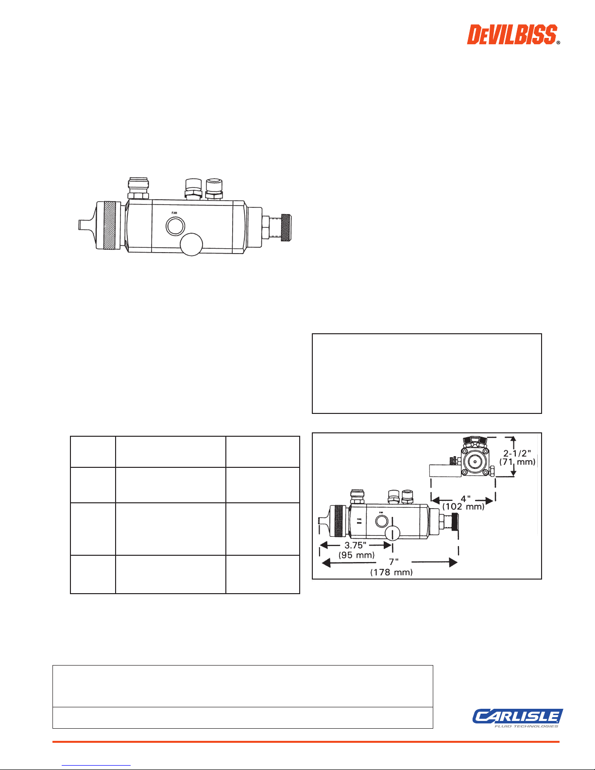
SPECIFICATIONS
Maximum Air Pressure 100 psi
Maximum Fluid Pressure 100 psi
Cylinder Air Pressure - Minimum*50 psi
- Maximum 100psi
Weight - without mounting stud 26 ounces
- with mounting stud 30.5 ounces
Mounting Stud Diameter 3/4" (see Accessories for Optional
1/2" mounting)
Wetted Parts - AGX-550 300 & 400 Gr.Stainless, PTFE
- AGX-552 300 & 400 Gr. S.S., carboloy, PTFE
- AGX-553 300 Gr. S.S., PTFE, U.H.M.W. Poly.
Hose Connections - Fluid Inlet 3/8" NPS(M)
- Cylinder Air 1/4" NPS(M)
- Atomization Air 1/4" NPS(M)
*For installations where 50 psi cylinder air is not available, the
inner (red) piston spring can be removed which lowers the minimum cylinder air to approximately 37 psi. Refer to Operations,
page 3, paragraph 2.
FLUID TIP ORIFICE SIZES
Letters on Tip Inch mm
AC .110" 2.8
D .086" 2.2
E .070" 1.8
EE .070" 1.8
FF .055" 1.4
FX .042" 1.1
G .028" .7
CHART 1 MODELS
Model No.
(Available Typical Fluid Tip/Needle
Tip Sizes) Applications Construction
AGX-550 Most conventional materials 400 Gr. Stainless
(AC, D, E, and most waterbornes and 303 Gr. Stainless
FF, FX, G) chlorinated solvents.
AGX-552 Abrasive materials (i.e. porcelain Carboloy, 400 Gr.
(D, EE, FF) enamel, ceramic glazes, buffing Stainless
compounds) and/or water mix
materials. Includes abrasive
fluid seal.
AGX-553 Waterbornes and more corrosive 303 Gr.Stainless
(E, FF, FX) materials (below 7 pH) w/U.H.M.W.poly.
insert
FIGURE 1 DIMENSIONS
Tools Required: Adjustable wrench for hose connections
1/2" six point box wrench for Ref. (3)
9/16" open wrench for Ref. (9)
3/16" hex wrench for Ref. (6)
Long neck pliers for Ref. (19)
1/8" hex key for Ref. (24)
1/2" and 9/16" socket wrench for Ref. (3) (9)
IMPORTANT! DO NOT DESTROY
It is the Customer's responsibility to have all operators and service personnel read and understand this manual.
Contact your local DeVilbiss representative for additional copies of this manual.
READ ALL INSTRUCTIONS BEFORE OPERATING THIS DEVILBISS PRODUCT.
SB-2-624-X (6/2017) 1 / 12 www.carlisleft.com
EN
SAFETY PRECAUTIONS
This manual contains important information that ALL users should know and understand BEFORE using the equipment. This information relates to USER SAFETY and PREVENTING EQUIPMENT PROBLEMS. To help you recognize
this information, we use the following terms to draw your attention to certain equipment labels and portions of this
manual. Pay special attention to any label or information that is highlighted by one of these terms:
CA PROP
PROP 65 WARNING
WARNING: This product contains
chemicals known to the State of
65
California to cause cancer and birth
defects or other reproductive harm.
Important information to alert you to a situation that
might cause serious injury or loss of life if instructions
are not followed.
Note
Important information that tells how to prevent
damage to equipment.
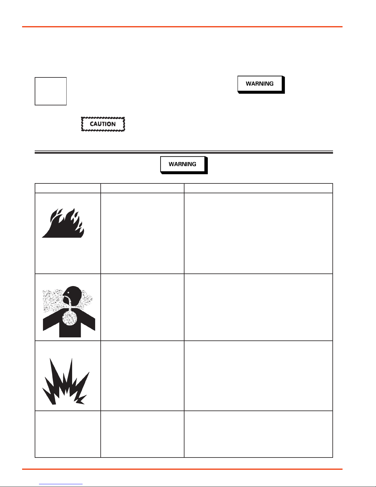
The following hazards may occur during the normal use of this equipment. Please read the following chart.
HAZARD CAUSE SAFEGUARDS
Fire
Inhaling Toxic Substances
Solvents and coatings can be
highly flammable or combustible,
especially when sprayed.
Certain materials may be harmful
if inhaled, or if there is contact
with the skin.
Information that you should pay special attention to.
1. Adequate exhaust must be provided to keep the air free
of accumulations of flammable vapors.
2. Smoking must never be allowed in spray area.
3. Fire extinguishing equipment must be present in the spray
area.
4. Static discharges must be prevented. Ground (earth) all
conductive objects in the spray area, such as a cleaning
solvent bucket, fire extinguisher, etc.
5. When using solvents for cleaning:
• Those used for equipment flushing must have a flash
point equal to or greater than that of the coating.
• Those used for general cleaning must have flash points
above 100°F (37.8°C).
1. Follow the requirements of the Safety Data Sheet supplied
by coating material manufacturer.
2. Adequate exhaust must be provided to keep the air free
of accumulations of toxic materials.
3. Use a mask or respirator whenever there is a chance of
inhaling sprayed materials. The mask must be compatible
with the material being sprayed and its concentration.
Equipment must be as prescribed by an industrial hygienist
or safety expert, and be NIOSH approved.
Explosion HazardIncompatible Materials
General Safety
Halogenated hydocarbon solvents- for example: methylene
chloride and 1,1,1,- Trichloroethane are not chemically compatible with the aluminum that
might be used in many system
components. The chemical reaction caused by these solvents
reacting with aluminum can
become violent and lead to an
equipment explosion.
Improper operation or maintenance may create a hazard.
The AGXV spray gun can be used with these solvents. However,
aluminum is widely used in other spray application equipment
— such as material pumps, cups, regulators, valves, etc. Check
all other equipment items before use and make sure they can
also be used safely with these solvents. Read the label or data
sheet for the material you intend to spray. If in doubt as to
whether or not a coating or cleaning material is compatible,
contact your material supplier.
Operators should be given adequate training in the safe use
and maintenance of the equipment (in accordance with the requirements of NFPA-33, Chapter 15 in U.S.). Users must comply with all local and national codes of practice and insurance
company requirements governing ventilation, fire precautions,
operation, maintenance and housekeeping (in the U.S., these
are OSHA Sections 1910.94 and 1910.107 and NFPA-33).
SB-2-624-X (6/2017)2 / 12www.carlisleft.com
EN
INSTALLATION
Mount the gun with the stud (13) or on a 5/16" dia. rod tightening
adequately with the 1/4-28 X 1/4" set screws (Ref. No. 24). See
"ACCESSORIES" for mounting clamps.
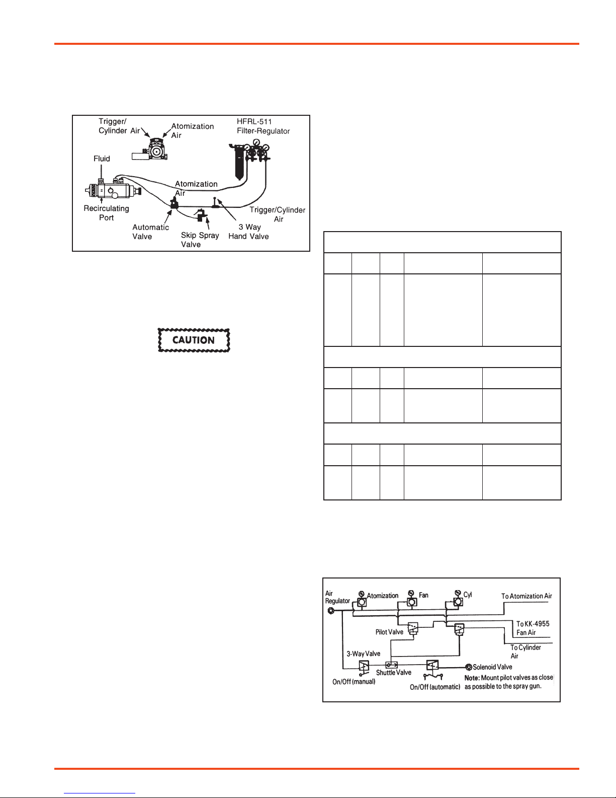
FIGURE 2 TYPICAL INSTALLATION
Attach trigger/cylinder air hose and atomization air hose to connections as indicated by markings on gun body. The air supply
should be filtered and regulated. Attach material hose to fluid
inlet on the body. Fluid can be recirculated by installing a fluid
fitting (AGX-415) (order separately) at recirculating port. See
Caution below.
The fluid inlet and recirculating ports have a tapered
seating surface intended for use with the AGX-415
fitting. Do not substitute other fittings as fluid leakage will occur.
Note
If replacing the atomization air connection (15) with
an elbow type connection, be aware of a possible air
flow (CFM) limitation. A 1/4" I.D. 90° elbow will only
pass 20 CFM @ 40 psi. Some air caps require more
than 20 CFM. Spray performance could be affected.
OPERATION
1. Mix, prepare and strain material to be sprayed according
to paint manufacturer’s instructions. Use a lint free mesh
to strain material.
2. Turn on cylinder air at source of supply. Supply air should be
a minimum of 50 PSI (3.5 bar). For consistant operation the
pressure should be regulated. If 50 psi cylinder air pressure
is not available, the red inner spring (31) can be removed.
This allows a minimum cylinder pressure of approximately
37 psi.
4. Adjust atomization air pressure to 50 PSI (3.5 bar). Aways
attempt to keep pressure as low as possible to minimize
overspray. The fluid pressure should be between 10 to 15
PSI (0.7 to 1.0 bar).
5. Open hand valve and/or trip automatic valve if installed
in system and observe spray pattern. Adjust air and fluid
pressures until desired pattern is obtained. Control fluid
pressure at source of supply. If desired regulation is not
practical at this point, restrict flow by turning adjustment
knob (25) clockwise.
6. The width of spray pattern is controlled by adjusting valve
(23) marked “FAN”. With “FAN” valve screwed fully clockwise, spreader air will be closed off causing a round pattern.
By gradually opening this valve, pattern changes to a fan
spray. The width is determined by amount valve is opened.
Atomization air is adjusted by regulating supply air to gun.
CHART 2 FLUID TIPS AND NEEDLES
AGX-550 GUN – 400 Gr. Stainless Tip / 303 Gr. Stainless Needle
Tip
Size
AGX-553 GUN – 303 Gr. Stainless & UHMW Poly.
Size
AGX-552 GUN – Carbolloy - Tip / Needle Set
Size
Adjustments to fan may be controlled remotely by using the
optional KK-4955 fan control adapter to replace the AGG-403
control valve (23).
FIGURE 2A AIR CIRCUIT EXAMPLE WITH
OPTIONAL KK-4955 REMOTE FAN CONTROL
in. mm Fluid Tip Number Needle Number
AC .110" 2.8 AV-2115-AC AGX-402-AC
D .086" 2.2 AV-2115-D AGX-402-D
E .070" 1.8 AV-2115-E AGX-402-E
FF .055" 1.4 AV-2115-FF AGX-402-FF
FX .042" 1.1 AV-2115-FX AGX-402-FX
G .028" 0.7 AV-2115-G AGX-402-G
Tip
in. mm Fluid Tip Number Needle Number
E .070" 1.8 AV-4915-E AGX-402-E
FF .055" 1.4 AV-4915-FF AGX-402-FF
FX .042" 1.1 AV-4915-FX AGX-402-FX
Tip
in. mm
D .086" 2.2 AV-1415-D AGX-4410-D
EE .070" 1.8 AV-1415-EE AGX-4410-EE
FF .055" 1.4 AV-1415-FF AGX-4410-FF
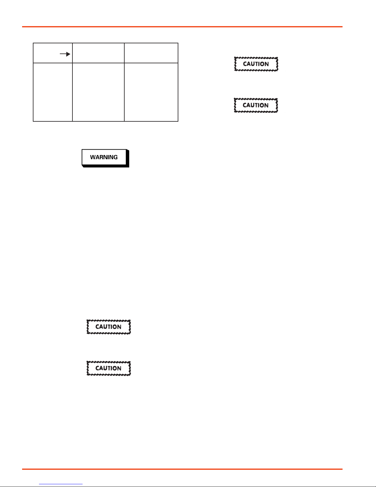
If this Number on
Tip order
➡
Tip / Needle Set
Note
If red inner spring (31) is removed, atomization pressure should not exceed 70 psi (will result in gun not
shutting off).
3. Turn needle adjustment knob (25) counterclockwise several turns. With cylinder air on, turn adjustment knob (25)
clockwise until it contacts piston (19) (for maximum fluid
flow). Back knob out 1/2 turn.
Note
Due to close part tolerances, actuate gun on and off 7 or
8 times to "break-in" the packings. Do this with material
supply off.
SB-2-624-X (6/2017) 3 / 12 www.carlisleft.com
7. Close automatic valves and begin operation.
EN
CHART 3 AIR CAPS
If this No. on Ref. No. (2) Ref. No. (1 & 2)
Cap, Order Air Cap Less Air Cap with
Retaining Ring Retaining Ring
24 AV-40-24
30 MB-4039-30
58 AV-439-58
62 MB-4039-62HD
64 MB-4039-64HD
704 AV-1239-704
765 AV-1239-765
777 31767-777
797 AV-1239-797
PREVENTIVE MAINTENANCE
Risk of Injury. Equipment and fluid may be under pressure. Pressure in the system must be relieved before
beginning the cleaning procedure and before replacing any parts. Follow the procedures in the service
literature provided with the system.
Cleaning
PARTS REPLACEMENT
Fluid needle (28) and Tip (3)
To prevent possible damage to the fluid tip (3) or needle
(28), always remove the adjustment knob (25) before
loosening or tightening the fluid tip.
To prevent possible damage to the spray gun, do NOT
loosen or tighten the fluid tip (3) if the fluid inlet (9) is
removed. The stainless steel insert may turn within
the gun body.
1. Relieve all air and fluid pressure in system.
2. Remove retaining ring (1) and air cap (2).
3. Remove fluid tip (3).
4. It is recommended that both the fluid tip (3) and needle
(28) be replaced at the same time. The needle packings (11)
should also be replaced when replacing the needle.
5. Remove baffle (5). It should be replaced if it is damaged or
filled with foreign material.
6. Remove adjusting knob (25).
7. Remove needle (28) with pliers.
8. Reassemble in reverse order.
1. Relieve air pressure from pressure feed tank.
Carefully follow instructions in the service bulletin sent
with tank.
2. Replace material in container with a suitable solvent.
3. Repressurize system.
4. Trigger gun and repeat procedure until gun and hose are
thoroughly clean. A SolventSaver™ type hose and gun
cleaner which supplies a mixture of air and solvent can be
used to most effectively clean gun and hose internal passages. See "Accessories" on back page. Wipe exterior of
gun with a solvent dampened cloth.
5. If a recirculating system is used, it may be necessary to fit a
shut off valve in return line to ensure fluid tip and forward
portion of sprayhead passage are properly cleaned when
flushed with solvent.
6. Refer to page 8 for optional gun annd hose cleaners.
Do not totally submerge gun in solvent. It is possible
to wash solids into air operating sections of gun which
could seriously damage piston o-ring seals.
The air cap can be immersed in solvent for cleaning. If
orifices are clogged, use a broom straw or toothpick
to remove obstruction. Never use a steel wire or hard
instrument. This will damage air cap and result in a
distorted spray pattern.
Fluid Needle (28) and Fluid Needle Packings (11)
1. With sprayhead (8) and adjusting knob (25) removed, the
fluid needle (28) and packings (11) can be easily removed
and replaced. See step 4 above.
2. Slide onto the new needle (28), in this order, 1 packing (11),
spring (12) and 1 packing (11). Be sure to orient packings
(11) as shown. For Model AGX-552, slide brass collar piece
and seal (32) over needle.
3. Insert new needle into gun and slide packings and spring
over needle.
4. Assemble sprayhead (8) with retaining screws (7).
5. Tighten screws (7) with a 3/16 hexagon key 30-40 in. lbs.
until the body is flush with sprayhead assembly.
Piston (19) , O-Rings (17 & 18) and Seal (20)
1. Remove piston housing (29) by removing rear retaining
screws (7).
2. Remove fluid needle (28).
3. Remove springs (30, 31 & 27) and piston (19). Care must be
taken when removing piston (19). Use a locking long nose
pliers to extract piston by clamping on inner ring on back
of piston.
4. Remove air packing (20), o-rings (17 & 18).
5. Wipe clean bore of cylinder. Replace piston o-rings (17 &
18) and lightly lubricate with clean petroleum jelly. See
Lubrication section which follows.
6. To replace air packing (20) (inside of piston), slide packing
(20) over the needle (28) with ead-in chamfer towards the
fluid tip end of needle. Insert needle into the piston (19). Hold
piston in your hand so that tip end of needle is protruding
downward (protect needle from damage). Lightly tap blunt
end of needle to drive packing down into piston. The needle
will stop inside piston at a shoulder.
7. Fit complete assembly into gun.
8. Lubricate outside of springs (27) and (30) (see Lubrication
section), then re-install springs and piston housing (29) and
tighten down and torque mounting screws (7) 30-40 in. lbs.
9. Lubricate adjustment knob threads (25) after cleaning with
SSL-10 Gun Lube. Loosen locking nut (26) before screwing
the adjustment knob in.
SB-2-624-X (6/2017)4 / 12www.carlisleft.com
 Loading...