

Page 1
Operation Manual: AGN-502 AUTOMATIC GUN
Important:
Read and follow all instructions and SAFETY PRECAUTIONS
before using this equipment
A lightweight diaphragm operated automatic spray gun for use with ceramic glaze, vitreous enamels, liquid polishing
compounds and similar materials. The standard gun fitted with a rubber diaphragm is not suitable for use with solvent based
coating materials, however it can be converted for use with solvent based coating materials by fitting a PTFE protective
diaphragm see Accessories. Nozzles are available in high grade stainless steel and case hardened Nitralloy steel.
Remotely positioned valves (supplied by user) control the air supplies for atomisation and diaphragm operation. Coating
material supply is by a pressure feed system.
IMPORTANT: These guns are not designed for use with highly corrosive or highly abrasive coating material and if used with
such materials it must be expected that the need for thorough cleaning and/or the necessity for replacement parts will be
increased. If there is any doubt regarding the suitability of a specific material, advise what material is to be used and/or submit
a sample for test.
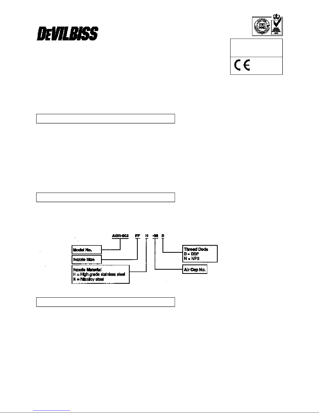
AGN-502 Spray gun fitted with fan air control valve.
For ordering information see chart 1 for the selection of air cap and nozzle combinations. Add thread code for the hose
connection thread required.
Example:
HOSE CONNECTIONS Thread code
‘B’ ‘N’
Air supply Atomising:
1
/4" BSP
1
/4" NPS
Diaphragm: 6mm push-in tube connector 6mm push-in tube connector
Coating material supply:3/8" BSP
3
’/8" NPS
MAXIMUM RECOMMENDED WORKING PRESSURES
Atomising air supply : P1=7 bar (100 lbf/in2)
Diaphragm air supply : P3=7 bar (100 lbf/in2)
Coating material supply : P2=6 bar (87 lbf/in2)
Air consumption: see chart 1
Weight: 560g.
SPECIFICATIONS
MODELS
DESCRIPTION
SB-E-2-660-D
© ITW LTD 1994
Page 2
2 © ITW LTD 1994 – SB-E-2-660
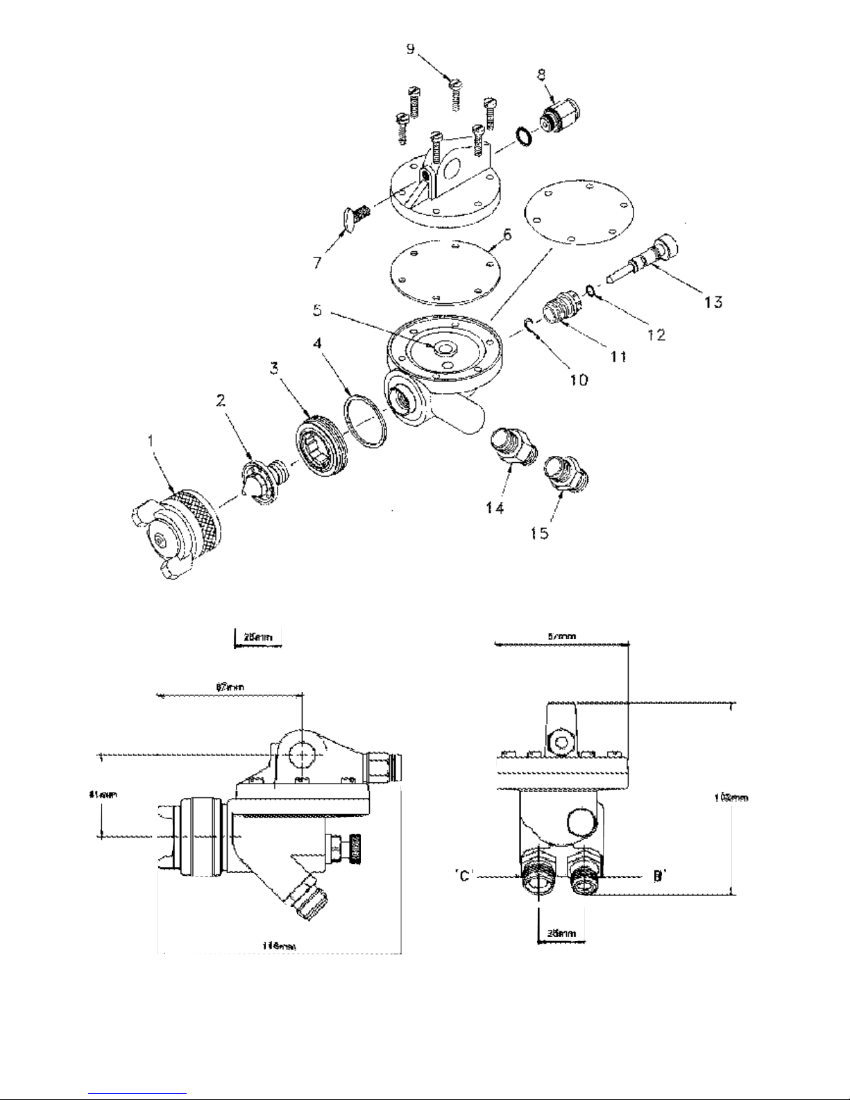
Figure 1
Figure 2
Page 3
SB-E-2-660 – © ITW LTD 1994 3
Chart 2 Nozzle Order No. (2)
Chart 1 Air cap order No. (1) and nozzle (2) size (mm) combinations.
Parts List
Ref. Order No. Description Qty.
1 Chart 1 Air cap 1
2 Chart 2 Nozzle 1
3 JGD-402 Baffle +Seal 1
*4 GTI-33-K5 Baffle 1
*5 AGN-18 Seat 1
*6 AGN-7 Diaphragm 1
7 SSF-5711-ZN Screw 1
8 SPS-13007 Tube connector 6mm 1
AC D DE E EE EX FF FJ FW FX FZ G Airflow
Pressure
No. Order No. 2.8 2.2 2.0 1.8 1.8 1.8 1.4 1.3 1.6 1.1 1.2 0.7 l/min bar
30 MB-4039-30 X X X X X X 275
3.4
35 AV-4239-35 X X X X X 144
4.1
43 AV-4239-43 X X X X X 396
4.1
58 AV-439-58 X X X X X X X 215
3.4
62 MB-4039-62 X 444
3.4
64 MB-4039-64 X X 462
3.4
67 MB-4039-67 X 467
3.4
78 MB-4039-78 X X X X X 617
4.1
80 MB-4039-80 X X X X X 391
4.1
186 AV-4239-186 X 331
3.4
704 AV-4239-704 X X X X X 419
3.4
705 AV-4239-705 X X X X X X 260
2.1
765 AV-4239-765 X X X X X X 547
4.8
777 AV-4239-777 X X X X 674
4.8
797 AV-4239-797 X X X X 680
4.8
880 MB-4039-880 X X 346
3.4
Ref. Order No. Description Qty.
9 SSF-4272-K6 Screw 6
10 SST-8434-K5 Circlip 1
11 JGS-143-1 Body 1
*12 SSG-8069-K5 ‘0’ ring 1
13 AGN-403 Valve Body 1
14
PA-H-2008 Connector 1/4" BSP
1
H-2008 Connector 1/4" NPS
15
PA-H-1580 Connector 3/8" BSP
1
H-1580-A Connector 3/8" NPS
NOZZLE ORDER No.
H – HIGH GRADE STAINLESS STEEL (HARD SEAT)
AV-1915-AC AV-645-AC
AV-1915-D AV-645-D
AV-1915-E AV-645-E
AV-1915-EX AV-645-EX
AV-1915-FF AV-645-FF
AV-1915-FV AV-645-FV
AV-1915-FW AV-645-FW
AV-1915-FX AV-645-FX
AV-1915-FZ AV-645-FZ
AV-1915-G AV-645-G
H – HIGH GRADE STAINLESS STEEL (SOFT SEAT)
AV-4915-D AV-651-D
AV-4915-E AV-651-E
AV-4915-EX AV-651-EX
AV-4915-FF AV-651-FF
AV-4915-FJ AV-651-FJ
AV-4915-FW AV-651-FW
AV-4915-FX AV-651-FX
AV-4915-FZ AV-651-FZ
AV-4915-G AV-651-G
N-NITRALLOY STEEL
AV-115-AC AV-611-AC
AV-115-D AV-611-D
AV-115-DE AV-611-DE
AV-115-EE AV-611-EE
AV-115-FF AV-611-FF
AV-115-FZ AV-611-FZ
Page 4

SAFETY WARNINGS
Solvents and coating materials can be highly flammable or combustible, especially when sprayed.
• Work stations must be provided with adequate ventilation/exhaust to prevent the build-up of flammable vapours.
• Smoking and naked flames must not be allowed in the spraying or mixing areas.
• Fire extinguishing equipment must be provided in the spraying and mixing areas.
Users must comply with all local and national codes of practice and insurance company requirements governing ventilation,
fire precautions, operation, maintenance and housekeeping of work stations.
HALOGENATED HYDROCARBON SOLVENTS - for example 1,1,1-Trichloroethane and Methylene Chloride can chemically
react with aluminium and galvanised or zinc coated parts and cause an explosion hazard. Read the label and data sheet of the
material you intend to spray.
DO NOT USE SOLVENTS OR COATING MATERIALS CONTAINING HALOGENATED HYDROCARBONS WITH THIS
EQUIPMENT.
STATIC ELECTRICITY - is generated by fluid moving through pipes and hoses. A static spark, capable of igniting certain
solvents and coating materials, could be produced by high fluid flow rates. To prevent the risk of fire or explosion, earth
continuity to the spray equipment and object being sprayed should be maintained.
TOXIC VAPOURS - when sprayed, certain materials may be poisonous, create irritation or otherwise be harmful to health.
Always read carefully all labels and safety/performance data for the material being sprayed and follow any recommendations.
IF IN DOUBT, CONSULT THE MATERIAL SUPPLIER.
• The use of respiratory protective equipment is recommended at all times when spraying. The type of respiratory protective
equipment used must be compatible with the material being sprayed and the level of concentration.
• Always wear eye protection when spraying or cleaning the equipment.
• Gloves must be worn for spraying or cleaning the equipment when certain coating materials and solvents are used.
Personnel should be given adequate training in the safe use and maintenance of this equipment. Training courses on all
aspects of the equipment are available. For details contact your local representative. The instructions and safety precautions
contained in this literature and the literature supplied with the coating material should be read and understood before the
equipment is used.
• All spray guns project particles at high velocity and must never be aimed at any part of the body.
• Never exceed the recommended safe working pressures for any of the equipment used.
• The fitting of non-recommended or non-original accessories or spare parts may create hazardous conditions.
• Before dismantling the equipment for cleaning or maintenance, all pressures, air and material, must be isolated and
released.
The disposal of non-metallic materials must be carried out in an approved manner. Burning may generate toxic fumes. The
removal of waste solvents and coating materials should be carried out by an authorised local waste disposal service.
The continuous A-weighted sound pressure level of this spray gun may exceed 85 dB(A) depending on the air cap/nozzle setup being used. Sound levels are measured using an impulse sound level meter and analyser, when the gun is being used in a
normal spraying application. Details of actual noise levels produced by the various air cap/nozzle set-ups are available on
request.
NOISE LEVELS
MISUSE
TRAINING
PERSONAL PROTECTIVE EQUIPMENT
FIRE AND EXPLOSION
4 © ITW LTD 1994 – SB-E-2-660
Page 5

IMPORTANT: To ensure that this equipment reaches you in first class condition, protective coatings, rust inhibitors etc., have
been used. Flush all equipment through with a suitable solvent before use to remove these agents from the material passages.
The AGN gun operation is different to models that have a needle valve to control the coating material flow. To shut coating
material flow off, air pressure must be maintained on the diaphragm (6) to seal against seat (5). The simplest method of gun
control is to use a normally open three way valve for the diaphragm air supply ‘A’ and a normally closed three way valve for the
atomising air supply ‘B’. These valves can automatically or manually operated.
To prevent unatomised coating material spoiling the finish the sequence of control valve operation should be;
To Spray 1. Atomising air ‘B’ ON
2. Diaphragm air ‘A’ OFF
Stop spraying 3. Diaphragm air ‘A’ ON
4. Atomising air ‘B’ OFF
The timing of these valve operations will depend on the speed of gun operation required, for some applications the atomising
air supply could be continuously ON and the diaphragm air control valve operated when spray is required.
CAUTION: In case of an air supply failure it is recommended that a fail-safe valve is fitted to the coating material supply to
prevent accidental spillage.
Separate filtered regulated air supplies are required for atomising and diaphragm operation.
Mount the gun on a 12.5 mm (1¼2") diameter rod and secure with screw (7).
Hosing
1. Connect a 6 mm outside diameter nylon tube to the push-in connector ‘A’ via a three way normally open valve.
2. Attach atomising air supply hose to connector ‘B’ via a three way normally closed valve.
3. Attach coating material hose to connector ‘C’ from a pressure feed source.
Recommended hose sizes, up to 10 metres long.
Atomising air supply 8mm (5/16") internal diameter.
Coating material supply 9.5mm (3/8") internal diameter.
The AGN gun operation is different to models that have a needle valve to control the coating material flow. To shut coating
material flow off, air pressure must be maintained on the diaphragm (6) to seal against seat (5). To prevent coating material
leaks from the nozzle the regulated diaphragm air supply pressure ‘A’ must be at least 0.5 bar (8 lbf/in2) higher than the coating
material supply.
CAUTION: To prevent accidental discharge of coating material always turn off and release coating material pressure when the
gun is not in use.
1. Mix, prepare and filter the coating material to be sprayed to the manufacturer’s instructions.
2. Adjust the spray gun control and regulate air and coating material pressures before turning on the air and coating material
supplies.
2.1. Fan pattern valve (13). Turn adjusting screw to fully open position, by turning counter- clockwise.
2.2. Regulate the atomising air supply ‘B’ pressure to 4 bar (60 lbf/in2).
2.3. Adjust diaphragm air supply pressure ‘A’ to 2 bar (30 lbf/in2).
2.4. Regulate coating material pressure to 1 bar (15 lbf/in2).
3. Turn on atomising and diaphragm air supply to the spray gun before turning on coating material supply. Test spray by
operating atomising and diaphragm air control valves,
Test Spray 1. Atomising air ‘B’ ON
2. Diaphragm air ‘A’ OFF
Stop spraying 3. Diaphragm air ‘A’ ON
4. Atomising air ‘B’ OFF
If the finish is too wet or dry adjust the coating material supply pressure until the desired pattern is achieved.
CAUTION: Remember to increase the diaphragm air pressure if the coating material pressure is increased.
If the atomisation is too coarse increase the air pressure, if too fine reduce the air pressure.
The recommended spray distance is 150-200 mm (6" – 8"). The spray width can be reduced from fan to round by turning valve
(13) clockwise.
OPERATION
INSTALLATION see figure 2
SB-E-2-660 – © ITW LTD 1994 5
Page 6

Flushing the system:
1. Turn off atomising air ‘B’ and coating material ‘C’ supplies and relieve pressures.
CAUTION: DO NOT turn off diaphragm air supply ‘A’.
2. Replace coating material with a suitable solvent, reduce pressure and turn on supply.
3. Remove air cap, operate the gun with diaphragm control valve, do not turn on atomising air supply. Flush system until
clean.
Clean air cap by immersing in solvent, brush or wipe clean. If any holes in the air cap are blocked use a toothpick or broom
straw to remove the obstruction. Never use a steel wire or hard implement which will damage the air cap and result in a
distorted pattern
Note: Order numbers shown in parts list for figure 1 with suffix ‘-K5’ etc. at the end of the order No. indicates a kit of parts.
Example JGD-14-K5 is a kit of five seals.
Caution: Always ensure that the fan air control valve is in the fully open position by turning the screw (13) ounter-clockwise
before fitting the valve assembly to the gun body and when removing the nozzle and baffle.
NOZZLE (2) AND BAFFLE (3).
Turn screw (13) counter-clockwise. Remove parts in the following order (1, 2, 3 and 4). Replace any worn or damaged parts.
Reassemble in reverse order.
Recommended tightening torque for nozzle (2), 25-27 Nm (221 - 239 lbf in).
SEAT (5) or DIAPHRAGM (6).
Remove screws (9), top plate and diaphragm (6). Unscrew seat (5) using a 1/4" hexagon key. Replace worn or damaged parts.
Reassemble in reverse order. Recommended tightening torque for screws (9), 4 Nm (35 lbf in).
Note: Protective diaphragm AGN-8 (see accessories) is fitted between the gun body and the rubber diaphragm (6) to prevent
solvent based coating material contacting the rubber diaphragm.
‘O’ RING (12).
Turn screw (13) counter-clockwise and unscrew valve body (11). Remove parts (10,13 and 12). Replace ‘0’ ring (12) and
reassemble in reverse order. Turn screw (13) counter-clockwise before fitting valve assembly to gun body.
CONNECTORS (14, 15).
Remove connector (14 or 15) and clean threads in gun body. Apply a medium strength thread locking/seal ing compound to
the taper thread of the new connector, screw into gun body and tighten. Recommended torque 16 Nm (140 lbf in).
Service kit Order KK-4998 contains parts marked with * in Parts List for figure 1.
Protective diaphragm Order AGN-8-K5. Converts gun for use with solvent based materials. Fit between the gun body and
standard rubber diaphragm.
Multipurpose spanner Order SPN-5. Contains necessary sizes for maintenance and hose connections.
Cleaning brush Order 4900-5-1-K3 for cleaning threads and recesses of gun.
Remote pressure Cup: maximum working pressure 2 bar (30 lbf/in2), capacity 2.0 litres. Add thread code to order No.,
B=BSP, N=NPS. Order hoses separately.
KB-522: NOT SUITABLE FOR USE WITH HYDROGENATED HYDROCARBON SOLVENTS OR WATERBOURNE
MATERIALS.
KB-522-SS: IS SUITABLE FOR USE WITH HYDROGENATED HYDROCARBON SOLVENTS OR WATERBOURNE
MATERIALS.
Pressure feed tanks: A range of sizes are available manufactured in zinc coated steel or stainless steel construction. Please
contact your local DEVILBISS Distributor for information.
ACCESSORIES
REPLACEMENT OF PARTS
PREVENTATIVE MAINTENANCE
6 © ITW LTD 1994 – SB-E-2-660
Page 7

CONDITION
CONDITION CAUSE CORRECTION
A 1. No pressure at the gun. 1. Check air and coating material lines.
2. Gun passages blocked. 2. Clean.
B & C 1. Coating material build-up on air 1. Clean air cap or nozzle.
cap or nozzle.
D 1. Coating material too thick or too much. 1. Thin or reduce coating material flow.
E 1. Not enough coating material. 1. Reduce atomising air pressure or
increase coating material flow.
F 1. Insufficient material in tank, cup or 1. Fill tank/cup, or clear obstruction.
an obstruction in the hose.
2. Gun material passage blocked. 2. Clean.
3. Worn seal (4). 3. Replace.
4. Loose or damaged nozzle. 4. Tighten or replace.
G 1. Incorrect air pressure on diaphragm 1. Increase air pressure to at leased
0.5 bar (8 lbf/in2) above coating
material pressure.
2. Seat (5) dirty or worn. 2. Clean or replace.
3. Damaged or worn diaphragm (6). 3. Replace.
4. Air leak from valve (13). 1. Replace ‘0’ ring (12).
SERVICE CHECKS
SB-E-2-660 – © ITW LTD 1994 7
NORMAL SPRAY PATTERN
A Will not spray
B C
D
E
G Dripping from nozzle (2)
F Fluttering Spray
Page 8

ITW Finishing Systems and Products
Ringwood Road
Bournemouth BH11 9LH England
Tel. No. (01202) 571111
Telex No. 41213
Telefax No. (01202) 581940
ITW Oberflächentechnik GmbH
Justus-von-Liebig-Straße 31
63128 Dietzenbach
Tel. (0 60 74) 403-1
Telex: 4 191 533
Telefax: (0 60 74) 403300
ITW Surfaces Et Finitions
163-171 avenue des Auréats B.P. 1453
26014 VALENCE CEDEX FRANCE
Tél. (33) 75-75-27-00
Télex 345 719F DVILBIS
8
 Loading...