

Page 1
SB-E-2-702
ISS.01
Operation Manual
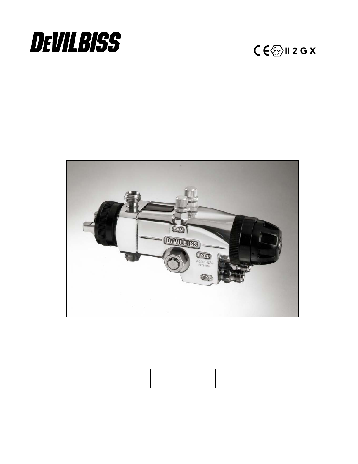
AGGS-522 –Automatic Spray Gun
E
P 1 – 12
Page 2
Operation Manual
AGGS-522 Automatic Spraygun
Important
Read and follow all instructions and Safety Precautions before using this
equipment
Description
The AGGS-522 is a production spray gun suitable for use with automatic and semi-automatic machines.
The design utilizes high volume low pressure atomization air (HVLP) to reduce overspray and improve coating
efficiency. To handle a wide range of coating materials the material passages are manufactured from high
grade stainless steel. Pressure feed material supply can be re-circulating or direct. A removable spray head
simplifies maintenance and cleaning of material wetted components. The gun is triggered by compressed air
to a single acting cylinder by a remotely positioned 3 way valve (supplied by user).
APPLICATIONS: General purpose solvent based and waterborne coating materials, food and pharmaceutical
processes.
IMPORTANT: These guns are not designed for use with highly corrosive or highly abrasive materials and if
used with such materials it must be expected that the need for thorough cleaning and/or the necessity for
replacement parts will be increased. If there is any doubt regarding the suitability of a specific material, advise
what material is to be used and/or submit a sample for test.
MODELS
The automatic spray gun type AGGS complies to ATEX regulations 94/9/EC, protection level II 2 G X T6
suitable for use in Zones 1 & 2.
For ordering information see chart for the selection of air cap, tip and needle combinations.
EXAMPLE: AGGS-522 FF H - 13
EC Declaration of Conformity
We, ITW Finishing UK, Ringwood Rd, Bournemouth, Dorset, BH11 9LH, UK, as the
manufacturer of the Spray gun model AGGS, declare, under our sole responsibility that the
equipment to which this document relates is in conformity with the following standards or other
normative documents:
BS EN 292-1 PARTS 1 & 2: 1991, BS EN 1953: 1999; and thereby conform to the protection
requirements of Council Directive 98/37/EEC relating to Machinery Safety Directive, and;
EN 13463-1:2001, council Directive 94/9/EC relating to Equipment and Protective Systems
intended for use in Potentially Explosive Atmospheres protection level II 2 G X.
B. Holt, General Manager
30th June 2003
ITW Finishing Systems and Products reserve the right to modify equipment specification without prior notice.
Basic part No
Fluid Tip size
Air Cap No
Fluid Tip Material
H = High grade Stainless Steel
Page 3
SPECIFICATIONS
Maximum WORKING PRESSURE
Universal Hose Connection
Air supply P1 : 9 bar
Atomization air: 1 / 4‘’BSP/NPS
Material supply P2 : 14 bar
Cylinder air: 1 / 4’’BSP/NPS
At the air cap : 0,7 bar
Min Cylinder Operating pressure : 4,5 bar
Material: 3 / 8’’BSP/NPS
Maximum service temperature
:
40° C
WEIGHT
:
950 g
MATERIAL of construction
Gun body Aluminium
Gun head Aluminium = Insert SS
Tip Stainless steel
Needle Stainless steel
Fluid inlet Stainless steel
AIR CAP (2), FLUID TIPS (3) & NEEDLES (16) SELECTION GUIDE
Air Cap Ref. 2 Fluid Tip Ref. 3 Needle Ref. 16
size Order No. size Order No. Order No.
Air Flow
l/min
Approx.
Material
flow @
0.7bar
Viscosity
range
ml/min (see
Note *)
Spray
distance
Ford No. 4
cup
Maximum
pattern
mm
13 JGHV-16-13 0.85m GX JGHV-473-GX-K AGGS-420-GX-K 480 150-200 19-24 180 305 X 63
13 JGHV-16-13 1.0mm FY JGHV-473-FY-K AGGS-420-FY-K 480 200-240 19-24 180 305 X 63
13 JGHV-16-13
1.4mm
FF
JGHV-473-FF-K AGGS-420-FF-K 425 220-280 19-24 180 355 X 63
18 JGHV-16-18
1.4mm
FF
JGHV-473-FF-K AGGS-420-FF-K 480 150-500 15-30
305
495 X 90
162 JGHV-16-162
1.4mm
FF
JGHV-473-FF-K AGGS-420-FF-K 510 300-350 20-30 180 365 X 63
162 JGHV-16-162
2.0mm
DE
JGHV-473-DE-K AGGS-420-DE-K 510 400+ 30+ 180 365 X 63
*NOTE: If you need to pre-set the flow rate, when using the AGGS-522 spray gun, by jetting material without
any atomizing air it will be necessary to compensate for the back pressure. The high performance of the
AGGS-522 is obtained differently to most other HVLP guns and so it will be necessary to increase the jetted
flow by approx. 30% to give the required atomised Low rate.
Page 4
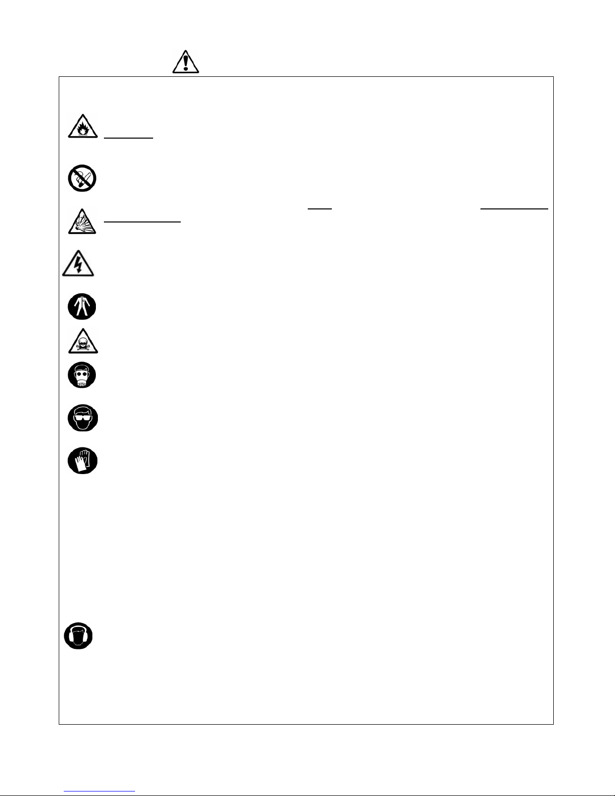
SAFETY WARNINGS
Fire and explosion
Solvents and coating materials can be highly flammable or combustible when sprayed.
ALWAYS refer to the coating material supplier’s instructions and COSHH sheets
before using this equipment.
Users must comply with all local and national codes of practice and insurance company
requirements governing ventilation, fire precautions, operation and house-keeping of
working areas.
This equipment, as supplied, is NOT suitable for use with Halogenated
Hydrocarbons.
Static electricity can be generated by fluid and/or air passing through hoses, by the
spraying process and by cleaning non- conductive parts with cloths. To prevent ignition
sources from static discharges, earth continuity must be maintained to the spray gun
and other metallic equipment used. It is essential to use conductive air and/or fluid
hoses.
Personal Protective Equipment
Toxic vapours – When sprayed, certain materials may be poisonous, create irritation or
be otherwise harmful to health. Always read all labels, safety data sheets and follow any
recommendations for the material before spraying. If in doubt, contact your material
supplier.
The use of respiratory protective equipment is recommended at all times. The type of
equipment must be compatible with the material being sprayed.
Always wear eye protection when spraying or cleaning the spray gun.
Gloves must be worn when spraying or cleaning the equipment.
Training – Personnel should be given adequate training in the safe use of spraying equipment.
Misuse
Never aim a spray gun at any part of the body.
Never exceed the max. recommended safe working pressure for the equipment.
The fitting of non-recommended or non-original spares may create hazards.
Before cleaning or maintenance, all pressure must be isolated and relieved from the equipment.
The product should be cleaned using a gun-washing machine. However, this equipment should
not be left inside gun-washing machines for prolonged periods of time.
Noise Levels
The A-weighted sound level of spray guns may exceed 85 dB (A) depending on the setup being used. Details of actual noise levels are available on request. It is
recommended that ear protection is worn at all times when spraying.
Operating
Spray equipment using high pressures may be subject to recoil forces. Under certain
circumstances, such forces could result in repetitive strain injury to the operator.
Page 5

Ref. Order No. Description
Qty
1
JGHV-24 RETAINING RING
1
2 CHART 1 AIR CAP 1
3*
CHART 1 FLUID TIP
1
4
JGHV-69 FRONT BAFFLE
1
5*
A
GG-88-K2 SEAL KIT OF 2
1
6
A
GGS-434-K REAR BAFFLE
1
7 SSF-3120-K4 SCREW KIT OF 4 4
8
A
GG-58 FLUID INSERT 3/8
2
9
A
GG-59 PLUG
1
10
A
GGS-419 SPRAY HEAD
1
11*
SSG-8099- ‘O’ RING KIT OF 10
2
12*
A
GG-444 PACKING SET
1
13*
A
GGS-31 PACKING PIECE
1
14*
SSN-1023-K6 DISC SPRING kit of 6
6
15
A
GGS-32-K5 RETAINING SCREW Kit of 5
1
16
CHART 2 NEEDLE
1
17
A
GG-33 COVER
1
18
A
GG-403 CONTROL VALVE
2
19*
SST-7711 SEAL
2
Ref. Order No. Description Qty
20
A
GG-39 SEAL RING
1
21
A
GGS-29 LOOKING RING
1
22*
A
GG-4 VALVE SEAT
1
23
A
GG-5 SPACER
1
24*
SSG-8102-K5 ‘O’ RING Kit of 5
1
25*
A
GG-415-K SEAL AND SPACER ASSY
1
26
A
GG-8 CYLINDER SLEEVE
1
27
SSG-8083-K5 ‘O’ RING Kit of 5
1
28
A
GG-410 PISTON ASSY
1
29
SST-7713 PISTON SEAL
1
30
SSF-2048-K5 SET SCREW Kit of 5
1
31
MSG-21
A
IR CONNECTOR UNIVERSAL
2
32*
A
GG-35-1 SPRING INNER
1
33*
A
GG-12-1 SPRING OUTER
1
34
A
GG-36 ZERO SLEEVE
1
35
A
GG-9 END CAP
1
36
A
GG-402-1 RATCHET ADJUSTER KNOB
1
37
SSF-2047 SCREW
1
38*
A
GGS-37-K5 SEAL Kit of 5
1
Page 6

6 © 2007 ITW Finishing Systems and Products
E
INSTALLATION
IMPORTANT: In order to ensure that this equipment reaches you in first class condition, protective
coatings, rust inhibitors, etc., have been used. Flush all equipment through with a suitable solvent before
use to remove these agents from material passages.
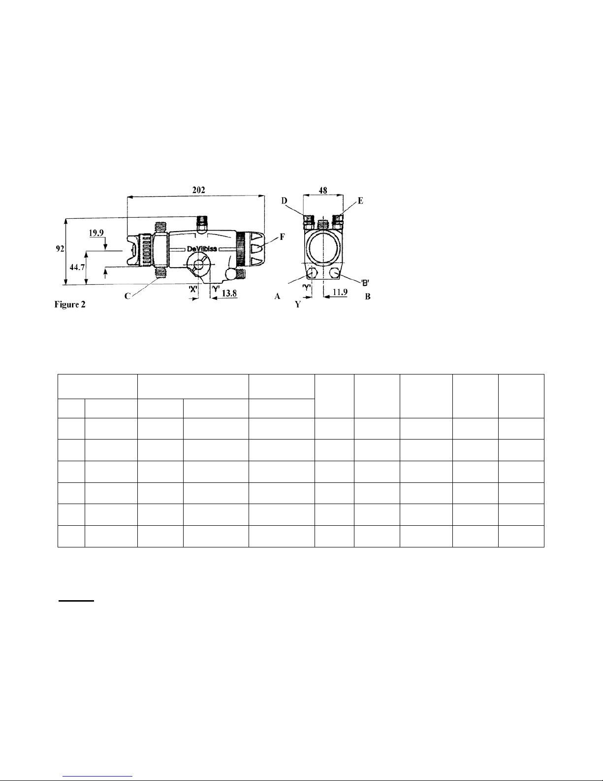
See figures 1 and 2 : Mount gun using the 12.7mm (1/2") diameter hole ‘X’ and secure with screw. An
additional 10mm diameter x 12.5mm deep dowel hole ‘Y’ has been provided to enable users to center
the spray gun with mounting fixtures of their own design.
HOSING
Use separate filtered regulated air supplies for atomizing and cylinder air.
Connect the cylinder air ‘A’ via a control valve. For fast cylinder operation the control valve should be
fitted as close to the gun as possible or an additional quick exhaust valve installed in the line.
Attach atomizing air hose to connector ‘B’
Connect material hose(s) ‘C’ to the spray head. If material re-circulation is not required, remove one of
the connectors and fit plug supplied with the gun.
EARTHING the Spray gun must be earthed to dissipate any electrostatic charges which may be created
by fluid or air flows. This can be achieved through the Spray gun mounting, or conductive air/fluid hoses.
electrical bond from the spray gun to earth should be checked with an ohmmeter. A resistance of less
than 10
6
Ohms is recommended.
WARNING: See instructions under “Replacement of Parts”.
Recommended hose sizes up to 10m (34ft) long:
Atomization Air: 8mm ( 5 /16") bore, Cylinder Air: 6mm ( 1 /4") bore, Material: 9.5mm ( 3 /8 ") bore.
OPERATION See figure 2.
1. Mix, prepare and strain the material to be sprayed according to the paint manufacturers instructions.
Use a lint free mesh to strain the material.
2. Adjust the spray gun controls and atomizing pressure before turning material supply on.
3. Open valves ‘D’ marked FAN and ‘E’ marked ATOM by turning counter-clockwise.
4. To adjust fluid needle for full travel. Close fluid needle adjusting knob ‘F’ clockwise until resistance is
felt, then open by turning 5 to 6 full turns counter clockwise.
5. Regulate cylinder air pressure to 4.5 bar (65lbf/in2).
6. Adjust atomizing air pressure. Start with a regulated pressure of 2 bar (30lbf/in2). Turn on cylinder
air and trigger spray gun with control valve. Increase regulated pressure to achieve 0,7 bar
(10lbf/in²). Turn off atomizing air supply and trigger spray gun to release pressure.
NOTE
: Use pressure test unit or test cap kit to check the atomizing pressure at the cap (See
accessories)
7. Turn on material supply and adjust material pressure to 0.7 bar (10 lbf/in2). See chart 1 for
guidance.
8. Test spray and observe spray pattern. Adjust material or air atomization pressures until the desired
pattern is obtained. If it is not practical to control the material flow by pressure regulation, the fluid
needle adjusting knob has ratchet stops and zero sleeve to aid fine material adjustment by
restricting the fluid needle movement. Close knob by turning clockwise and gradually open using
ratchet stops until the correct material flow is achieved.
9. Other adjustments can be made using the valves marked ‘Fan’ and ‘Atom’. The fan valve will alter
the spray width from full fan to round. ‘Atom’ valve controls the degree of atomization from fine to
coarse.
NOTE
: If the process requires altering the spray width recheck and adjust the air cap atomizing
pressure (See 2.4 above)
PREVENTIVE MAINTENANCE
FLUSHING THE SYSTEM.
1. Turn off atomizing air supply and material supply.
2. Relieve system pressures, open material relief valve and trigger gun into booth or container.
3. Remove air cap.
4. Replace material with a suitable solvent.
Page 7

© 2007 ITW Finishing Systems and Products 7
E
5. Turn on solvent supply and flush hose and gun by triggering gun or re circulation.
NOTE
: It may be necessary to fit a shut-off valve to the return line on circulating systems and trigger the
gun to clean front portion of the spray head and fluid tip.
Air cap, clean by immersing in solvent, brush or wipe clean. If any holes in the air cap are blocked use a
toothpick or broom straw to remove obstruction. Never use a steel wire or hard implement which will
damage the air cap and result in a distorted pattern.
REPLACEMENT OF PARTS
NOTE: Order numbers shown in parts list for figure 1 with suffix “-K2” etc. at the end of the number
indicates a kit of parts. Example: Ref 5. AGG-88-K2 is a kit of two seals.
TO REMOVE SPRAY HEAD ASSEMBLY See Figure 1.
Disconnect material hose(s). Unscrew the retaining ring and remove the air cap
1. Using a small screwdriver remove the black plastic cover (17) at the top of the spray gun. Check that
the slot in the piston (28) is uppermost so that the fluid needle (16) can be removed. If the slot is not
in the correct position remove knob (36) and use a screwdriver in the center hole of the end cap (35)
to rotate the piston (28) to its correct position.
2. Remove the 4 hexagon socket screws (7) holding the spray head (10) to the body.
3. Pull the spray head (10) forward to disengage the locating pin.
4. Slide the spray head (10) up to disengage fluid needle (16) from piston (28). With spray head
removed all components can easily be removed and replaced.
Material Connectors/Plug (8, 9)
WARNING: To provide protection from the ingress of Halogenated Hydrocarbon materials, the spray
head material passages are sealed. It is essential when fitting connector/plug (8, 9) that sealing
compound is applied and it is tightened to the recommended torque. Do not remove or tighten fluid tip (3)
if connector(s) (8, 9) are not fitted to the spray head, as it may loosen the spray head insert and cause
irreparable damage.
Remove connector(s)/plug with a 6mm hexagon key and clean threads in the spray head. Apply a
medium strength thread locking/sealing compound to the external chamfer and threads of the new
connector. Screw into spray head and tighten. Recommended Torque : 8Nm (70lbf in).
Fluid tip (3) and/or baffle (4 , 5 & 6)
Unscrew the fluid tip (3) remove front and rear baffle (4 & 6) and seals (5, 38), replace if damaged. When
replacing the fluid tip a new seal (5) is required.
Re-assemble ensuring that the fluid tip seats correctly in the spray head. Tighten fluid tip.
Recommended torque 16Nm (140lbf in).
Fluid Needle (16) and Packing Set (12)
To overcome problems experienced with needles jamming, follow this procedure to ensure correct
needle movement and needle packing adjustment. Remove Spray Head Assembly, Fluid Tip (3) and
Baffle (4, 5 and 6) as described.
4.1. Remove needle (16).
4.2. Remove retaining screw (15) using a hexagon key, remove disc springs (14), packing piece (13)
and needle packing set (12) over needle (16). Refer to enlarged view on Figure 1.
Page 8

8 © 2007 ITW Finishing Systems and Products
E
4.3. Fit new retaining screw (15), disc springs (14), packing piece (13) and needle packing set (12)
over needle (16).
4.4. Insert assembly into Spray Head and screw in retaining screw (15) by hand.
4.5. Remove needle (16) and re-insert from opposite end (See Figure 3).
4.6. Draw needle (16) back until the hexagon key fits into the retaining screw without touching the
end of the needle (See Figure 4).
4.7. Fully tighten retaining screw then back off approximately half a turn – check the needle
movement. The needle should not require excessive force to be moved or be loose – adjust if
necessary.
4.8. Remove needle (16).
4.9. Re-assemble baffle (4, 5 and 6) and fluid tip (3) with new seals as described.
4.10. Re-fit needle (16) in correct orientation.
5. Re-assemble spray head to gun. Check ‘O’ rings (11) are in position. Engage fluid needle (16) into
piston. Push spray head in and align with location pin, tighten screws (7). Refit air cap and material
hose(s).
TO DISMANTLE GUN BODY, See Figure 1.
Disconnect hoses and release screw (30).
5.1. Remove spray head assembly see steps 1 to 4 and ratchet knob (36).
5.2. Piston (28) and Seals (19, 22 and 29).
5.3. Remove end cap (35) using pin spanner which is part of the accessory tool kit AGG-412.
5.4. Remove springs (32 and 33) and piston (28). Care must be taken when removing the piston
(28) from the gun to ensure that the front forks do not damage the front seal (19).
5.5. Remove the cylinder sleeve (26), accessory tool J-24728 can be used to extract it from the
body.
5.6. Remove the seal and spacer (25), ‘O’ ring (24), spacer (23) and valve seat (22).
5.7. Using the hexagon key tool provided in the AGG-412 accessory tool kit, remove the seal locking
ring (21), front seal (19) and seal ring (20).
5.8. Fit new front seal (19) into the locking ring (21) and using the hexagon key re-assemble, with
seal ring (20) into body.
5.9. To replace piston seal (29), clamp accessory tool J-24708 into vice jaws, pins upwards. Position
holes in piston (28) onto tool locating pins. Remove piston end cap and seal (29), clean end cap
threads and end of piston. Fit new seal to piston, wipe clean the bore of the cylinder sleeve (26)
and apply a light coating of soft petroleum jelly, remove ‘O’ ring (27) and replace with a new
one.
Push cylinder sleeve over piston seal (29) ensuring the end of the cylinder sleeve with the
identification groove is pushed on first. Apply one drop of medium strength thread
locking/sealing compound to the threads of the piston end cap and assemble to piston.
Carefully tighten piston end cap, compressing seal (29) until end cap makes contact with the
back face of the piston. Recommended torque: 3.5Nm (30lbf in).
NOTE: This assembly should be left standing upright for 1 hour to allow to compound to
cure.
5.10. Re-assemble valve seat (22) ensuring lip is facing out towards the back of the gun body.
5.11. Re-assemble spacer (23) and ‘O’ ring (24).
5.12. Remove piston and cylinder sleeve assembly from tool and carefully push seal and spacer (25)
onto piston with lips of seal facing away from cylinder sleeve.
5.13. Fit complete assembly into gun.
5.14. Refit springs (32 and 33), zero sleeve (34) and end cap (35) and tighten down to ensure all
inner components have been securely compressed into position. Recommended torque 2124Nm (190-210lbf in).
5.15. Using a screwdriver rotate piston (28) so that forks are facing upwards to allow spray head to be
fitted.
Page 9

© 2007 ITW Finishing Systems and Products 9
E
5.16. Re-assemble spray head and knob (36). See step 5
6. Connectors (31), remove connector and clean threads in the gun body. Apply a medium
strength thread locking/sealing compound to the new connector’s thread and screw into gun
body, do not over tighten leave approximately 2mm of thread visible above the gun body face.
Recommended torque 17–18Nm (150–160lbf in).
ACCESSORIES
TEST CAP and GAUGE KIT: Order KK-4559 add cap N° Example: KK-4559-18 to check atomizing
pressure remove cap and fit test cap and gauge.
SERVICE KIT : Order KK-4566 add fluid tip size required Example KK-4566-FFH
. Parts marked with *
are included in the kit..
GUN MOUNTING STUD KIT: Order Nr. KK-4573.
TOOL KIT: Order AGG-412. Comprising 4mm hexagon key for (7,
15, 11). Key Wrench for (21). Pin spanner for (35). 1.5mm; hexagon
key for (37).
EXTRACTOR TOOL: Order J-24728 for (26).
PISTON ASSEMBLY FIXTURE: Order J-24708, for seal (29) replacement.
REMOTE ‘FAN’ CONTROL ADAPTOR Order AGG-75.
For an independently regulated fan air supply, remove ‘FAN’ valve (D) and fit adaptor.
NOTE : It is possible to exceed 0,7 bar (10lbf/in²) at the air cap with the use of this adaptor.
Page 10

10 © 2007 ITW Finishing Systems and Products
E
SERVICE CHECKS
CAUSE CORRECTION
A
1) No pressure at the gun
2) Piston stops moving
A
1) Check air/material lines
2) Check adjusting knob (36)
B-C
1) Material build-up on air cap/fluid
tip
2) Worm or damaged seal (5)
B-C
1) Clean air cap/fluid tip
2) Replace seal.
D
1) Material too thick or too much
D
1) Thin or reduce material flow
E
1) Not enough material
E
1) Reduce air pressure or increase
material flow
F
1) Insufficient material in tank or an
obstruction in the hose.
2) Gun material passage blocked
3) Worn packing (12)
4) Loose or damaged fluid tip
F
1) Fill tank or clear obstruction
2) Clean.
3) Replace.
4) Tighten or replace.
G
1) Packing worn (12)
2) Rough needle shaft (16)
G
1) Replace packing
2) Polish contact point with packing with
fine emery cloth
H
1) Worn packing (12)
2) Worn or damaged fluid tip (3) or
needle (16)
3) Worn seals
H
1) Replace
2) Replace
3) Replace valve (18).
Page 11

© 2007 ITW Finishing Systems and Products 11
E
Page 12

12 © 2007 ITW Finishing Systems and Products
E
ITW Finishing Systems and Products
Ringwood Road,
Bournemouth,
BH11 9LH,
England.
Tel. No. (01202) 571111
Telefax No. (01202) 581940,
Website address
http://www.itweuropeanfinishing.com
ITW Oberflächentechnik GmbH & Co.
KG
Justus-von-Liebig-Straße 31
63128 Dietzenbach
Tel (060 74) 403-1
Telefax: (060 74) 403300
Website address
http://www.itw-finishing.de
ITW Automotive Finishing UK
Anchorbrook Industrial Estate
Lockside
Aldridge,
Walsall,
UK.
Tel. No. (01922) 423700
Telefax No. (01922) 423705,
Website address
http://www.itweuropeanfinishing.com
ITW Surfaces Et Finitions
163-171 avenue des Auréats B.P.
1453
26014 VALENCE CEDEX FRANCE
Tél. (33) 475-75-27-00
Télex 345 719F DVILBIS
Téléfax: (33) 475-75-27-99
ITW Finishing Systems and Products is a Division of ITW Ltd. Reg. Office:
Admiral House,
St Leonard’s Road,
Windsor,
Berkshire,
SL4 3BL,
UK
Registered in England: No 559693 Vat No 619 5461 24
 Loading...