

Page 1
© ITW LTD 1994
SB-E-2-782-B
Operation Manual:
AGF-508 Automatic Gun
Important:
Read and follow all instructions and SAFETY PRECAUTIONS
before using this equipment
A lightweight automatic spray gun for small work suitable for use with most solvent based coating materials. The design
features, a single air supply to operate the single acting cylinder and provide the atomising air. A remotely positioned two-way
control valve (supplied by user) triggers the gun. Coating material supply is by a pressure feed system.
IMPORTANT: These guns are not designed for use with highly corrosive or highly abrasive coating material and if used with
such materials it must be expected that the need for thorough cleaning and/or the necessity for replacement parts will be
increased. If there is any doubt regarding the suitability of a specific material, advise what material is to be used and/or submit
a sample for test.
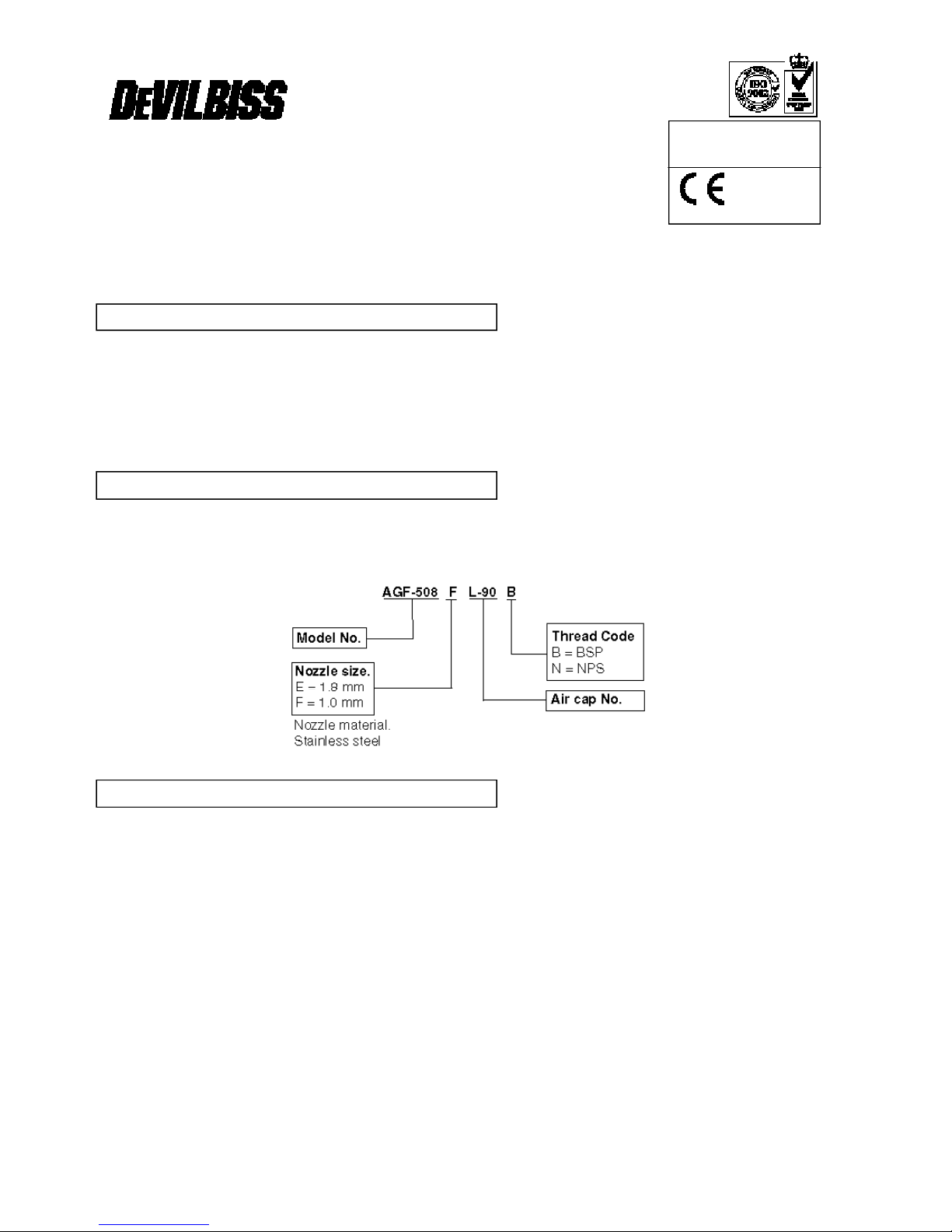
AGF-508EL-92 Spray gun fitted with 1.8 mm nozzle and No. 92 air cap.
AGF-508FL-90 Spray gun fitted with 1.0 mm nozzle and No. 90 air cap.
When ordering add the hose connecting thread required.
HOSE CONNECTION: THREAD CODE
‘B’ ‘N’
Air supply:
1
/4" BSP
1
/4" NPS
Coating material supply:
1
/4" BSP
1
/4" NPS
MAXIMUM RECOMMENDED WORKING PRESSURES:
Air supply : P1= 7 bar (100 lbf/in2).
Coating material supply : P2= 7 bar (100 lbf/in2).
MINIMUM CYLINDER AIR PRESSURE:
: 4 bar (60 lbf/in2).
WEIGHT:
Gun less mounting stud : 375g.
Mounting stud : 110g.
SPECIFICATIONS
MODELS
DESCRIPTION
Page 2
2
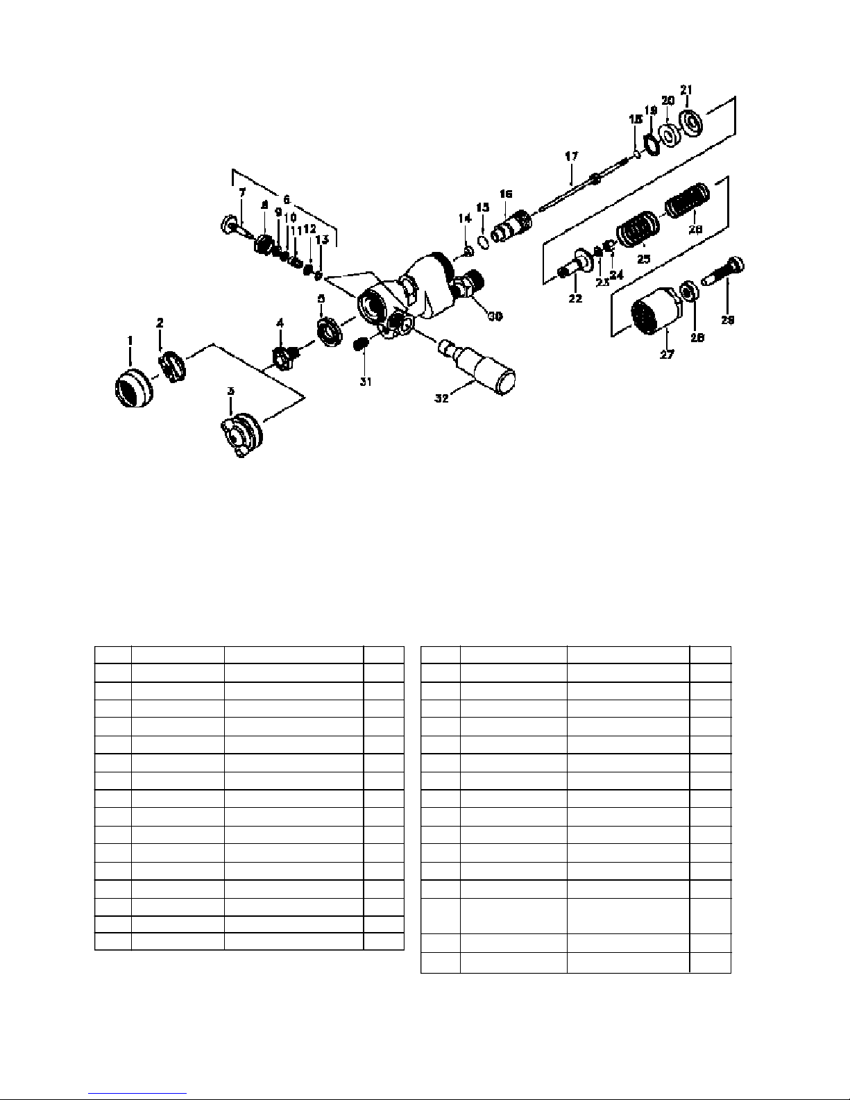
Figure 1
Ref. Order No. Description Qty.
1 TGA-31 Air cap retaining nut 1
2 CV-39-90 Air cap 1
3 CV-439-92 Air cap / retaining ring 1
*4 Chart 1 Nozzle 1
5 AGF-5 Baffle 1
6 AGF-403 Valve assembly 2
7 AGF-7 Valve 2
8 AGF-8 Body 2
9 AGF-9 Seal 2
10 AGF-10 Washer 2
11 KN-40-K5 Spring 2
12 21172-007-K10 Washer 2
13 25746-007-K5 Circlip 2
*14 AG-12-K5 Needle Packing 1
*15 23162-024-K10 ‘0’ ring 1
16 AGF-6 Seal retainer 1
Ref. Order No. Description Qty.
*17 Chart 1 Needle 1
*18 MBC-1164-K5 ‘0’ ring 1
*19 SST-8402 Circlip 1
20 AGF-19 Spacer 1
*21 VA-246 Piston seal 1
22 AGF-36 Piston 1
23 21175-093 Washer 1
24 AGF-15 Nut 1
*25 AGF-33 Spring 1
*26 AGF-32 Spring 1
27 AGF-31 End cap 1
28 AGF-35 Locknut 1
29 AGF-34 Screw 1
30 H-1766 Connector 1/4" NPS
PA-H-1766 Connector 1/4" BSP
31 SS-555 Screw 1
32 AGF-20 Mounting stud 1
Parts List
2 SB-E-2-782 – © ITW LTD 1994
Page 3

1. Mix, prepare and filter the coating material to be sprayed to the manufacturer’s instructions.
2. Adjust the spray gun controls and pressures before turning on the air and coating material supplies.
2.1 Fan pattern valve (6) marked ‘FAN’ on the gun body. Turn adjusting screw to fully open position, by turning
counter-clockwise.
2.2 Atomising control valve (6) marked ‘ATOM’ on the gun body. Turn adjusting screw to fully open position, by
turning counter-clockwise.
2.1 Needle adjustment. Fully close needle adjusting screw (29), release locknut (28), turn clockwise until resistance is
felt, then turn to the fully open position by turning counter-clockwise ten turns and secure with locknut (28).
3. Regulate the air supply pressure to 4 bar (60 lbf/in2) and coating material pressure to 1 bar (15 lbf/in2)
4. Turn on air and coating material supplies and test spray by operating control valve. The recommended spray distance is 150
mm (6"). If the finish is too wet, reduce the coating material supply pressure, or turn the needle adjusting screw (29) fully
clockwise then gradually open until the desired pattern is achieved. If the atomisation is too coarse increase the air
pressure. The spray width can be reduced from fan to round by turning fan adjusting valve (6) marked ‘FAN’ clockwise.
Note. If both ‘FAN’ and ‘ATOM’ valves (6) are closed the air supply operates the cylinder only and will allow coating material to
be jetted from the nozzle.
5. To prevent accidental discharge of coating material, always turn off and release pressure when the gun is not in use.
Flushing the system:
1. Turn off coating material supply and relieve pressure.
2. Close both air valves (6) marked ‘FAN’ and ‘ATOM’.
3. Replace coating material with a suitable solvent, reduce pressure and turn on supply.
4. Remove air cap, trigger the gun by operating the control valve. Flush system until clean.
Clean air cap by immersing in solvent, brush or wipe clean. If any holes in the air cap are blocked use a toothpick or broom
straw to remove the obstruction. Never use a steel wire or hard implement which will damage the air cap and result in a
distorted pattern.
Lubrication: Daily lubricate with light mineral oil the valve stems (7) and needle seal (14) through holes in seal retainer (16).
Occasionally coat the gun body cylinder section and springs (25 & 26) with mineral based grease.
Note: Order numbers shown in parts list for figure 1 with suffix ‘-K5’, etc. at the end of the order No. indicates a kit of parts.
Example AG-12-K5 is a kit of five seals.
Nozzle (4) or Baffle (5)
Remove parts (1, 2, 3, 27, 28, 29, 25 and 26) unscrew nozzle (4) and pull baffle (5) out from body.
Caution: Do not twist baffle (5) when removing from the gun body as this will bend the locating pin in the gun body.
Replace any worn or damaged parts. Reassembly, position baffle (5), ensure gun body locating pin is engaged in the narrow
slot in the baffle. Replace nozzle (4) and tighten. Recommended torque 13-14 Nm (115-125 lbf in). Fit parts (25, 26,27, 28, 29,
1, 2 or 3).
Seal (9)
Caution: Always turn valve (7) fully counter-clockwise before fitting or removing valve assembly (6) from gun body.
Remove valve assembly (6) from gun body. Remove parts (13, 12, 11, 10 and 9). Lubricate seal (9) with mineral oil and
replace parts (9, 10, 11, 12 and 13). Refit valve assembly (6) to gun.
Seal (14), (SEE SAFETY WARNINGS UNDER MISUSE), and ‘0’ ring (15)
Remove parts (29, 28, 27, 26 and 25). Withdraw needle and piston assembly, insert a wide blade screwdriver into the slot and
unscrew seal retainer (16) and remove seal (14). Lubricate new seal (14) with mineral oil, replace ‘0’ ring (15), place seal (14)
into retainer (16) and screw into gun body. Tighten retainer (16) sufficiently to seal but not to impede free needle (17)
movement. Lightly coat seal (21) and ‘0’ ring (18) with mineral based grease. Fit needle and piston assembly into gun body.
Reassemble parts (29, 28, 27, 26 and 25).
Needle (17)
Remove parts (29, 28, 27, 26 and 25) and withdraw needle and piston assembly. Unscrew nut (24), remove needle (17) and
washer (23). Replace needle (17), position washer (23) and tighten nut (24). Adjust needle seal (14) with retainer (16)
sufficiently to seal but not to impede free needle (17) movement. Lightly coat seal (21) and ‘0’ ring (18) with mineral based
grease. Fit needle and piston assembly into gun body. Reassemble parts (29, 28, 27, 26 and 25).
Piston seal (21) and ‘0’ ring (18)
Remove parts (29, 28, 27, 26 and 25) and withdraw needle and piston assembly. Remove parts (18, 19, 20, 21). Replace seal
(21) and ‘0’ ring (18). Reassemble parts (18, 19, 20, 21) see figure 3 for the direction of circlip bow. Lightly coat seal (21) and ‘
0’ ring (18) with mineral based grease. Fit needle and piston assembly into gun body. Reassemble parts (25, 26, 27, 28 and
29). Adjust screw (29) and secure with locknut (28).
Connectors (30)
Remove connector (30) and clean threads in gun body. Apply a medium strength thread locking/sealing compound to the
external threads of the new connector. Screw into gun body and tighten. Recommended torque: 14 Nm (125 lbf in).
REPLACEMENT OF PARTS (see figures 1 and 3)
PREVENTIVE MAINTENANCE
OPERATION
3 SB-E-2-782 – © ITW LTD 1994
Page 4

4 © ITW LTD 1994 – SB-EE-4-205
SAFETY WARNINGS
Solvents and coating materials can be highly flammable or combustible, especially when sprayed.
• Work stations must be provided with adequate ventilation/exhaust to prevent the build-up of flammable vapours.
• Smoking and naked flames must not be allowed in the spraying or mixing areas.
• Fire extinguishing equipment must be provided in the spraying and mixing areas.
Users must comply with all local and national codes of practice and insurance company requirements governing ventilation,
fire precautions, operation, maintenance and housekeeping of work stations.
HALOGENATED HYDROCARBON SOLVENTS - for example 1,1,1-Trichloroethane and Methylene Chloride can chemically
react with aluminium and galvanised or zinc coated parts and cause an explosion hazard. Read the label and data sheet of the
material you intend to spray.
DO NOT USE SOLVENTS OR COATING MATERIALS CONTAINING HALOGENATED HYDROCARBONS WITH THIS
EQUIPMENT.
STATIC ELECTRICITY - is generated by fluid moving through pipes and hoses. A static spark, capable of igniting certain
solvents and coating materials, could be produced by high fluid flow rates. To prevent the risk of fire or explosion, earth
continuity to the spray equipment and object being sprayed should be maintained.
TOXIC VAPOURS - when sprayed, certain materials may be poisonous, create irritation or otherwise be harmful to health.
Always read carefully all labels and safety/performance data for the material being sprayed and follow any recommendations.
IF IN DOUBT, CONSULT THE MATERIAL SUPPLIER.
• The use of respiratory protective equipment is recommended at all times when spraying. The type of respiratory protective
equipment used must be compatible with the material being sprayed and the level of concentration.
• Always wear eye protection when spraying or cleaning the equipment.
• Gloves must be worn for spraying or cleaning the equipment when certain coating materials and solvents are used.
Personnel should be given adequate training in the safe use and maintenance of this equipment. Training courses on all
aspects of the equipment are available. For details contact your local representative. The instructions and safety precautions
contained in this literature and the literature supplied with the coating material should be read and understood before the
equipment is used.
• All spray guns project particles at high velocity and must never be aimed at any part of the body.
• Never exceed the recommended safe working pressures for any of the equipment used.
• The fitting of non-recommended or non-original accessories or spare parts may create hazardous conditions.
• Before dismantling the equipment for cleaning or maintenance, all pressures, air and material, must be isolated and
released.
The disposal of non-metallic materials must be carried out in an approved manner. Burning may generate toxic fumes. The
removal of waste solvents and coating materials should be carried out by an authorised local waste disposal service. The
needle packing contains Chrysotile (white) asbestos fibres impregnated with PTFE or graphite. The phyical/chemical binding
processes used in the manufacture of these seals prevent any health or safety hazards in normal use, handling or storage.
The disposal of seals should be in accordance with local or national regulations.
The materials used in the construction of this equipment are (bearing in mind the warning on Halogenated Hydrocarbons)
solvent resistant enabling the equipment to be cleaned using gun washing machines. However, this equipment must not be left
inside the gun washing machine for prolonged periods of time after the automatic cleaning cycle has been completed. The
solvents used in the gun washing machine should be regularly checked to ensure that the equipment is not flushed through
with contaminated material. Follow the recommendations of the machine manufacturer.
The continuous A-weighted sound pressure level of this spray gun may exceed 85 dB(A) depending on the air cap/nozzle setup being used. Sound levels are measured using an impulse sound level meter and analyser, when the gun is being used in a
normal spraying application. Details of actual noise levels produced by the various air cap/nozzle set-ups are available on
request.
NOISE LEVELS
MISUSE
TRAINING
PERSONAL PROTECTIVE EQUIPMENT
FIRE AND EXPLOSION
Page 5

© ITW LTD 1994 – SB-E-2-782 5
CHART 1 Air cap number, nozzle and needle size combinations.
No. Air cap (2, 3) Nozzle (4) Needle (17)
Order No. Size Order No. Order No.
90 CV-39-90 1.0 mm CV-30-F-K AGF-404-F-K
92 CV-439-92 1.8 mm CV-30-E-K AGF-404-E-K
Figure 2
Figure 3
IMPORTANT: To ensure that this equipment reaches you in first class condition, protective coatings, rust inhibitors etc., have
been used. Flush all equipment through with a suitable solvent before use to remove these agents from the material passages.
Note: A single hose supplies both atomising and cylinder air. To prevent unatomised coating material being expelled from the
nozzle at the end of the spray cycle, all air should be exhausted through the gun. It is recommended that a two-way
valve should be fitted in the control line. If a three-way valve is used, install a plug in the exhaust port.
1. Mount gun on a 9.5 mm (3/8") rod or stud (32) and secure with screw (31). A universal clamp is available see accessories, for
use with stud (32) to attach the gun to a 19 mm (3/4") rod.
2. Connect air and coating material supplies to connectors (30) indicated by markings “AIR” and “FLUID” on the gun body.
Note: Use a filtered regulated air supply. The minimum air supply pressure required to operate the cylinder is 4 bar (60 lbf/in2).
Recommended hose sizes:
Air supply Coating material supply
Length up to 5 m long 6 mm (1/4") bore. 6 mm (1/4") bore.
10 m long 8 mm (5/16") bore. 8 mm (5/16") bore.
INSTALLATION
Page 6

CONDITION
CAUSE CORRECTION
A 1. No pressure at the gun. 1. Check air/material lines.
2. Gun passages blocked. 2. Clean.
3. Screw (29) not properly adjusted. 3. Adjust.
B & C 1. Coating material build-up on air cap/nozzle. 1. Clean air cap/nozzle.
D 1. Coating material too thick or too much. 1. Thin or reduce coating material flow.
E 1. Not enough coating material. 1. Reduce air pressure or increase
1 coating material flow.
F 1. Insufficient coating material in tank, 1. Fill tank/cup, or clear obstruction.
1 cup or hose blocked.
2. Loose or damaged nozzle. 2. Tighten or replace.
G 1. Seal worn (14). 1. Replace seal.
2. Seal retainer (16) loose. 2. Adjust.
H 1. Dry seal (14). 1. Lubricate.
2. Seal retainer (16) tight. 2. Adjust.
3. Worn or damaged nozzle (4) 3. Replace.
3.or needle (17).
Service kit: Order KK-4514 add nozzle size required. Example: KK-4514-F-L.
Parts marked with * are included in the kit.
Universal clamp Order 3600 Attaches gun stud (32) to a 19 mm (3/4") diameter rod. Allows gun to be positioned at any angle
Multipurpose spanner: Order SPN-5. Contains necessary sizes for maintenance and hose connections.
Cleaning brush:Order 4900-5-1-K3 for cleaning threads and recesses of gun.
Remote pressure Cup: Order KB-522 maximum working pressure 3.5 bar (30 lbf/in2), capacity 2.0 litres. Add thread code to
order No. B=BSP, N=NPS. Order hoses separately.
Pressure feed tanks: A range of sizes are available manufactured in zinc coated steel or stainless steel construction. Please
contact your local DEVILBISS Distributor for information.
ACCESSORIES
SERVICE CHECKS
NORMAL SPRAY PATTERN
A Will not spray
B
D
C
E
F Fluttering Spray
G Fluid leakage from packing nut
H Dripping from nozzle (2)
Page 7

SB-EE-4-205 – © ITW LTD 1994 7
NOTES
Page 8

ITW Finishing Systems and Products (A division of ITW Ltd)
Ringwood Road
Bournemouth BH11 9LH England
Tel. No. (01202) 571111
Telex No. 41213
Telefax No. (01202) 581940
ITW Oberflächentechnik GmbH
Justus-von-Liebig-Straße 31
63128 Dietzenbach
Tel. (0 60 74) 403-1
Telex: 4 191 533
Telefax: (0 60 74) 403300
ITW Surfaces Et Finitions
163-171 avenue des Auréats B.P. 1453
26014 VALENCE CEDEX FRANCE
Tél. (33) 75-75-27-00
Télex 345 719F DVILBIS
Téléfax: (33) 75-75-27-99 ITW LTD JANUARY 1998 © ITW LTD 1994 – SB-E-2-782
 Loading...