

DeVilbiss AG360 Series, AG362 Service Manual
EN
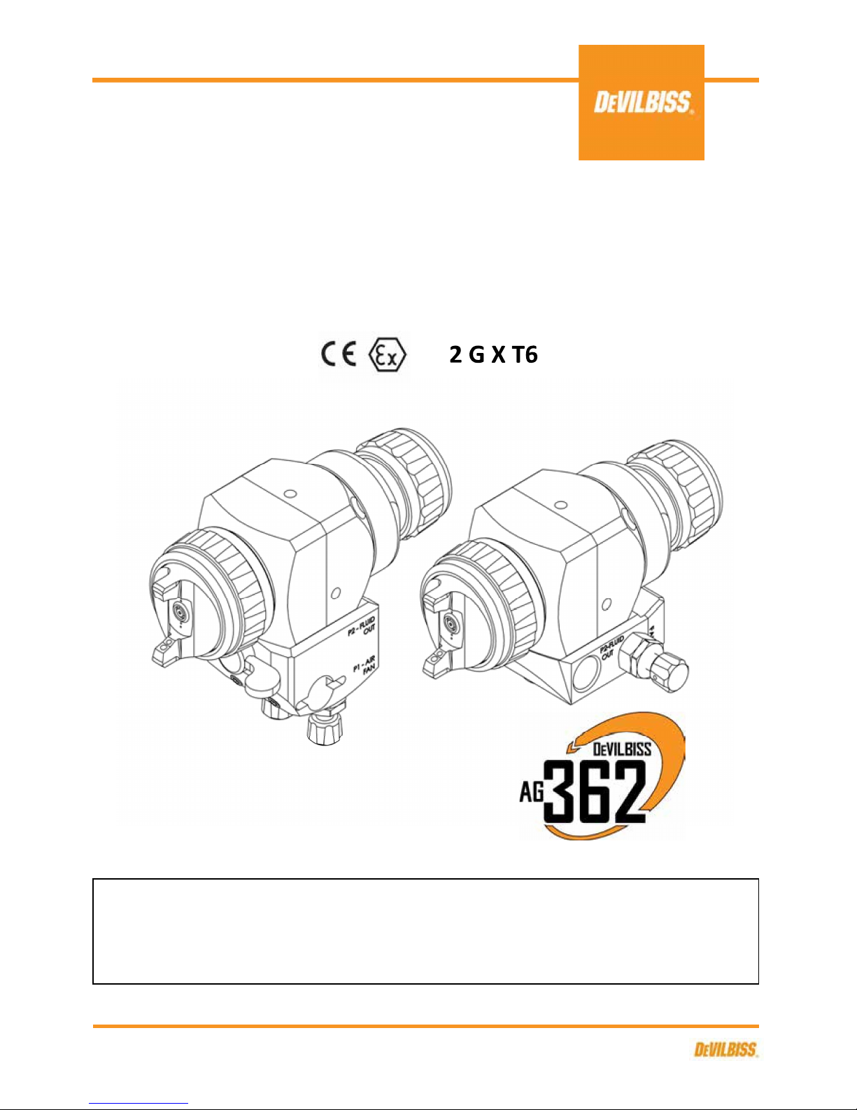
AG362 Low Pressure, Air Atomisation Automatic
Spray Gun, with Lever or Screw Type Manifold.
SERVICE MANUAL
DEVILBISS AG360 Series:
Contact your local DeVilbiss representative for additional copies of this manual.
IMPORTANT! DO NOT DESTROY
It is the Customer's responsibility to have all operators and service personnel read and understand this
manual.
II
READ ALL INSTRUCTIONS BEFORE OPERATING THIS DEVILBISS PRODUCT.
SB-E-2-643 R5.0
1/28
EN
P1=
P2=
P3=
P1= 1/8" G
P2= 1/8" G
P3= 1/8" G
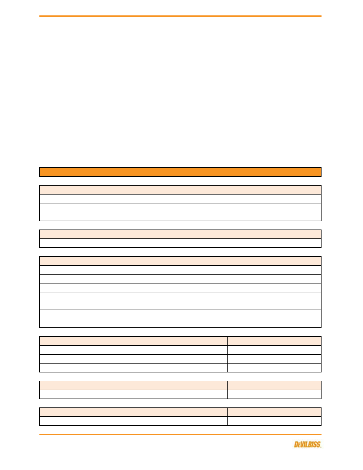
DIMENSIONS WITH MANIFOLD
FUNCTIONAL DESCRIPTION
SPECIFICATIONS
MANIFOLD CONNECTIONS
L x H x W mm
WEIGHT WITH MANIFOLD
127 x 97 x 44 127 x 64 x 89
7 Bar [102 psi]
7 Bar [102 psi]
Max Air Input Pressure
Max Fluid Input Pressure
Cylinder Air Pressure 4 - 7 Bar [58 psi - 102 psi]
40°C Nominal [104°F]Max Ambient Operating Temperature
Electroless Nickel Plated Brass
Gun Body Material
Air Cap Material
Fluid Tip and Needle Construction
Stainless Steel
Stainless Steel
Nitride Coated Stainless Steel
Fluid Inlet Size
Cylinder Inlet
Seals and O-Rings HDPE, Viton Extreme
LEVER TYPE
LEVER TYPE
LEVER TYPE
SCREW TYPE
SCREW TYPE
SCREW TYPE
1/4" G
1/4" NPS
1/8" G
940g 850g
Quickclean™ Coated Aluminium
WEIGHT
The AG362 low pressure air atomising spray guns are designed to be fast changeover, modular
construction applicators, for spray finishing on machines and fixed mountings.
The AG362 can be mounted on either a rear entry, lever operated, fast detachable manifold, or a
screw attached, low profile manifold, dependant on the part number selected and mounting
preference.
The AG362 is intended for most types of general industrial coating and fine finishing operations,
suitable for both water based and solvent based applications.
Guns are available with a range of Conventional, Trans-Tech (High Efficiency) and HVLP atomisation
air caps, to give a choice of atomisation and Transfer Efficiency parameters.
The gun is designed as a flexible solution for the modern coating applicator, with multiple accessories
available, to further optimise the process.
FLUID AND AIR INLET PRESSURES
ENVIRONMENTAL
MATERIALS OF CONSTRUCTION
Gun Head and Fluid Passageways
Air Inlet Size
SB-E-2-643 R5.0
2/28
EN
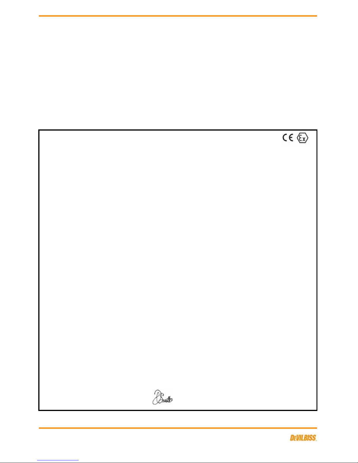
Product Description:
Machinery Directive 2006/42/EC
ATEX Directive 94/9/EC
Finishing Brands UK,
Ringwood Road,
Bournemouth, BH11 9LH. UK
Protection Level: II 2 G X T6
N/A
Sound Pressure Level:
Suitable for use in hazardous area: Zone 1 & 2
Vibration Level:
We: Finishing Brands UK, declare that the above product conforms with the Provisions of:
AG362
BS EN 1953:2013 Atomising and spraying equipment for coating materials - Safety requirements
by complying with the following statutory documents and harmonised standards:
D Smith (General Manager)
Solvent and water based materials
EU Declaration of Conformity
EN 14462:2005+A1:2009 Surface treatment equipment - Noise test code for surface treatment equipment including its ancillary handling
equipiment - Accuracy grades 2 and 3
30/01/15
HVLP and Trans-Tech products comply with the requirements of PG6 from the EPA guidelines and offer greater than 65% transfer efficiency.
EN ISO 11201:1995 Acoustics - Noise by machinery and equipment - Determination of emission sound pressure levels at a work station and
at other specified positions in an essentially free field over a reflecting plane with negligible environmental corrections
EN1127-1: Explosive atmospheres - Explosion prevention - Basic concepts
EN 13463-1: Non electrical equipment for use in potentially explosive atmospheres - Basic methods and requirements
This Product is designed for use with:
Available on request
Sound Power Level: Available on request
Manufacturer:
EN ISO 12100-1:2010 Safety of Machinery - Basic concepts, general principles for design - Basic terminology, methodology
EN ISO 12100-2:2010 Safety of Machinery - Basic concepts, general principles for design - Technical principles
SB-E-2-643 R5.0
3/28
EN
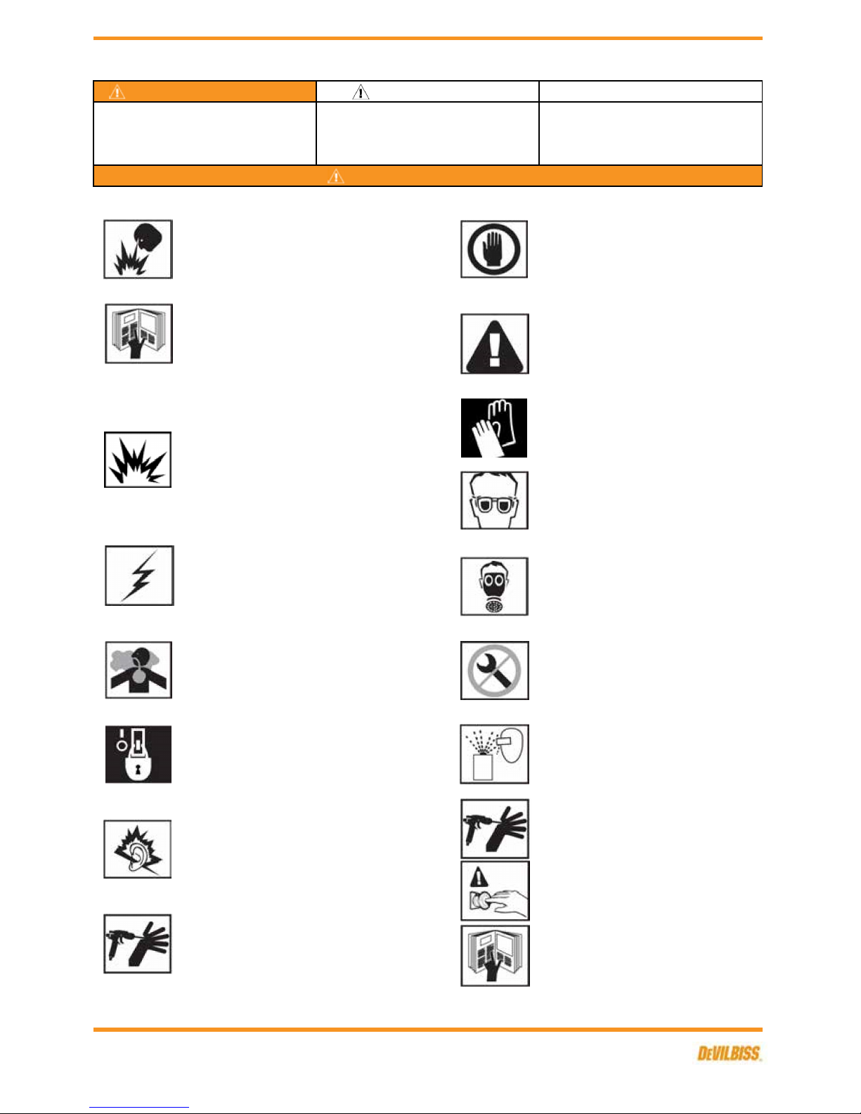
GLOVES. Must be worn when spraying or cleaning the
equipment.
HIGH PRESSURE CONSIDERATION. High pressure can cause serious injury.
Relieve all pressure before servicing. Spray from the gun, hose leaks or
ruptured components can inject fluid into your body and cause extremely
serious injury.
WARNING
WEAR RESPIRATOR. The use of respiratory protective
equipment is recommended at all times. The type of equipment
must be compatible with the material being sprayed.
NEVER MODIFY THE EQUIPMENT. Do not modify the
equipment unless the manufacturer provides written approval.
In this part sheet, the words WARNING, CAUTION and NOTE are used to emphasise important safety information as
follows:
NOTE
IT IS THE RESPONSIBILITY OF THE EMPLOYER TO PROVIDE THIS INFORMATION TO THE OPERATOR OF THE EQUIPMENT.
NOISE LEVELS. The A-weighted sound level of pumping and spray equipment
may exceed 85 dB(A) depending on equipment settings. Actual noise levels are
available on request. It is recommended that ear protection is worn at all times
while equipment is in use.
PROJECTILE HAZARD. You may be injured by venting liquids or
gases that are released under pressure, or flying debris.
CAUTION
Read the following warnings before using this equipment.
KNOW WHERE AND HOW TO SHUT OFF THE EQUIPMENT IN
CASE OF AN EMERGENCY.
Hazards or unsafe practices which could result in
minor personal injury, product or property
damage.
EQUIPMENT MISUSE HAZARD. Equipment misuse can cause
the equipment to rupture, malfunction or start unexpectedly and
result in serious injury.
WARNING
WEAR SAFETY GLASSES. Failure to wear safety glasses with
side shields could result in serious eye injury or blindness.
SOLVENTS AND COATING MATERIALS. Can be highly flammable or
combustible when sprayed. Always refer to the coating material supplier's
instructions and safety sheets before using this equipment.
READ THE MANUAL. Before operating finishing equipment, read and
understand all safety, operation and maintenance information provided in the
operation manual. Users must comply with all local and national codes of
practice and insurance company requirements governing ventilation, fire
precautions, operation and house-keeping of working areas.
Important installation, operation or maintenance
information.
INSPECT THE EQUIPMENT DAILY. Inspect the equipment for
worn or broken parts on a daily basis. Do not operate the
equipment if you are uncertain about its condition.
FIRE AND EXPLOSION HAZARD. Never use 1,1,1-Trichloroethane, Methylene
Chloride, other Halogenated Hydrocarbon solvents or fluids containing such
solvents in equipment with aluminium wetted parts. Such use could result in a
serious chemical reaction, with the posibility of explosion. Consult your fluid
suppliers to ensure that the fluids being used are compatible with aluminium
parts.
STATIC CHARGE. Fluid may develop a static charge that must be dissipated
through proper grounding of the equipment, objects to be sprayed and all other
electrically conductive objects in the dispensing area. Improper grounding or
sparks can cause a hazardous condition and result in fire, explosion or elecrtic
shock and other serious injury.
TOXIC VAPOURS. When sprayed, certain materials may be poisonous, create
irritation, or are otherwise harmful to health. Always read all labels, safety
sheets and follow any recommendations for the material before spraying. If in
doubt contact your material supplier.
PRESSURE RELIEF PROCEDURE. Always follow the pressure
relief procedure in the equipment instruction manual.
Hazards or unsafe practices which could result in
severe personal injury, death or substantial
property damage.
OPERATOR TRAINING. All personnel must be trained before
operating finishing equipment.
LOCK OUT / TAG-OUT. Failure to de-energise, disconnect, lock out and tagout all power sources before performing equipment maintenance could cause
serious injury or death.
SB-E-2-643 R5.0
4/28
EN
C
TE
HV
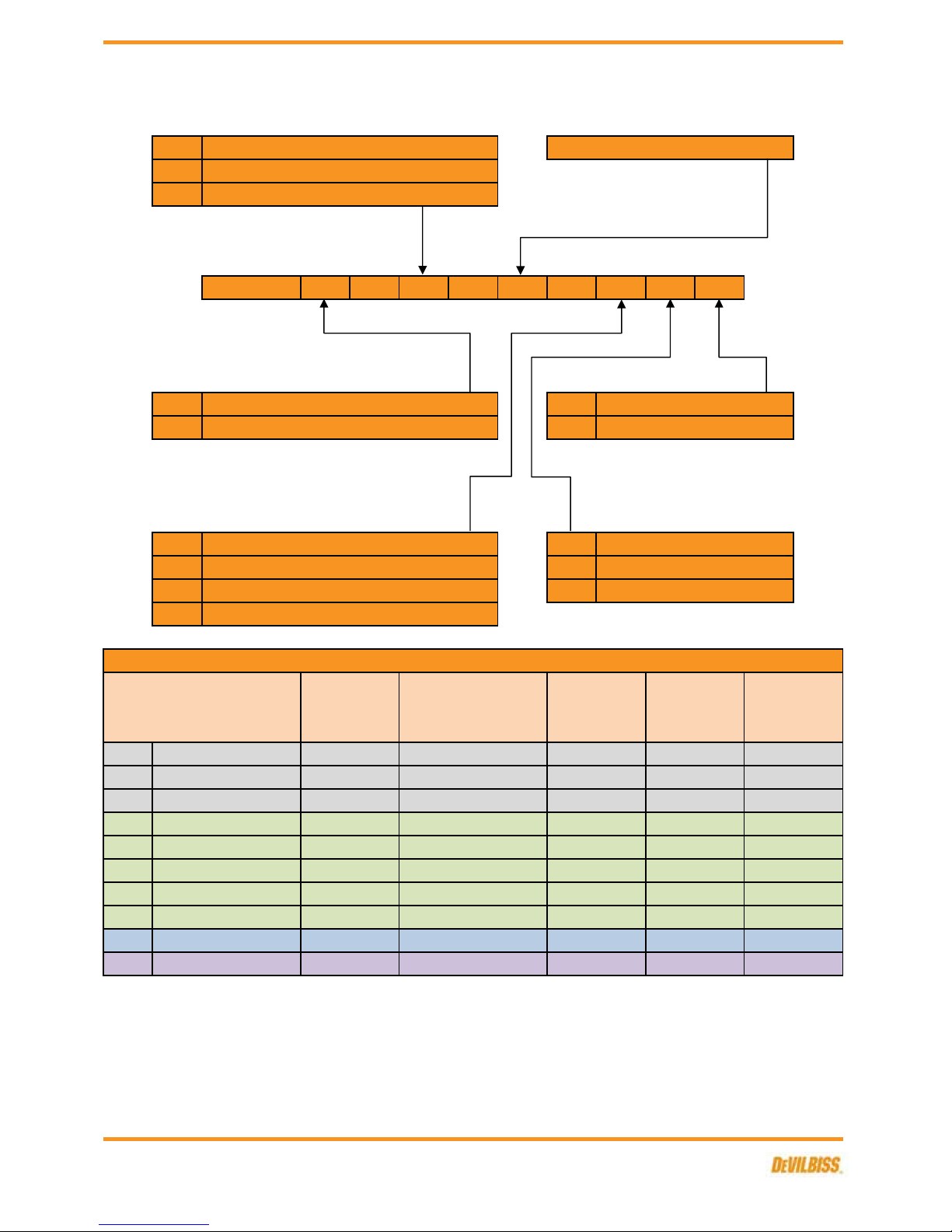
U - TE10 - 085N - L F P
U P
L F
S M
T
C1
C2
C3
TE10
TE20
TE30
TE40
TE50
HV30***
R40
*
**
***
150-200 ml/min
Air Consumption
290 L/min [10.3 cfm]
440 L/min [15.7 cfm] 3 Bar [45 psi]
Trans-Tech/Compliant 2 Bar [30 psi]255 L/min [9.1 cfm] 300mm
250-600 ml/min
See table 1
Recommended
Air Inlet Pressure
PROC-120-C1-K
Air Cap & Type
Conventional
See pages 8 & 10
Single hole head feed
Head recirculation
HVLP
Trans-Tech/Compliant
100-350 ml/min
150-200 ml/minTrans-Tech/Compliant
PROC-120-C2-KConventional
Conventional
PRO-100-TE10-K
Part Number
PROC-120-C3-K
300 L/min [10.7 cfm] 3 Bar [45 psi]
325 L/min [11.6 cfm]
FLUID TIP
AG362
AIR CAP
PRO-100-TE40-K
Trans-Tech/Compliant
355 L/min [12.6 cfm]Trans-Tech/Compliant
PRO-100-TE30-K
GUN HEAD FLUID PASSAGEWAYS
TABLE 1 - AG362 AIR CAP PERFORMANCE GUIDE
VALVE OPTIONS
BACK END OPTIONS
Control Valve
Plugged
Gun only
Screw manifold - recirculation
Lever manifold
Screw manifold - no recirculation
200-300 ml/min
Trans-Tech/Compliant 2 Bar [30 psi]
PRO-100-HV30-K
PRO-100-TE50-K
Flow rates may vary according to paint/material and pressure used.
2 Bar [30 psi]450 L/min [16.0 cfm]
250-400 ml/min
160-200 ml/min
425 L/min [15.1 cfm]
HV30 (HVLP) operates at 0.7 Bar [10 psi] atomisation air pressure at the cap.
300mm
HVLP 315mm
300mm
380mm
2 Bar [30 psi]
2 Bar [30 psi]
270mm
270mm
360mm
Fixed
Micrometer
290mm2 Bar [30 psi]
Typical Fan
Pattern Size**
250-400 ml/min
375 L/min [13.3 cfm]
3 Bar [45 psi]
See table 2
150-250 ml/min
Typical Fluid
Flow*
Conventional
PRO-100-TE20-K
Ratchet
MANIFOLD TYPE
Size & construction
AG362 GUN PART NUMBER FORMAT & PART SELECTION GUIDE
Fan pattern size @ 200mm distance.
Trans-Tech/Compliant PRO-102-R40-K 110 L/min [4.0 cfm] 3 Bar [30 psi] 150-300 ml/min 70mm
SB-E-2-643 R5.0
5/28

EN
- - SN SN SN SN SN SN - - -
- - SN SN SN SN SN SN - - -
- - SN SN SN SN SN SN - - -
- - SN SN SN SN SN SN SN SN -
- - SN SN SN SN SN SN SN SN -
- - SN SN SN SN SN SN SN SN -
- - SN SN SN SN SN SN SN SN -
- - SN SN SN SN SN SN SN SN -
- - SN SN SN SN SN SN SN SN -
- - SN SN SN SN SN SN SN SN -
S =
N =
TABLE 2 - AG362 RECOMMENDED FLUID TIP / AIR CAP COMBINATIONS
0.7mm 0.85mm 1.0mm
Trans-Tech
Conventional
Conventional
Conventional
Fluid Tip
C1
C2
Trans-TechTE20
Trans-Tech
Trans-TechTE40
PROC-215-14-K
PROC-215-16-K
Stainless Steel Nitride Hardened
Needle
Nitride hardened tips & needles also available in this type & size.
1.4mm
PRO-205N-12-K1.2
C3
TE40R
TE30
Trans-Tech
Fluid Tip Size
High quality stainless steel tips & needles available in this type & size.
TE10
PRO-205N-10-K
SPA-362-085-10-K
1.8 PROC-215-18-K
Nitride Hardened
Fluid Tip Needle
2.8mm
0.85 PRO-205N-085-KPRO-205-085-K
HVLP
PROC-215-10-K
PROC-215-12-K
SPA-362-085-10-K
For Trans-Tech / HVLP tip & needle part numbers, see table 4.
0.85
1.0
1.2
HV30
1.4
1.6
Fluid Tip Size
PROC-215-085-K
Stainless Steel
Fluid Tip Needle Fluid Tip Needle
PROC-215N-085-K
SPA-362N-085-10-K
PROC-215N-10-K
2.0mmAIR CAP Atomisation Type 1.6mm1.2mm 1.8mm 2.2mm0.5mm
PROC-215N-12-K
SPA-362-12-14-K
SPA-362-16-18-K
1.0
1.8
1.6
SPA-362N-12-14-K
PROC-215N-14-K
PROC-215N-16-K
SPA-362N-16-18-K
PROC-215N-18-K
PRO-205-10-K
For Conventional tip & needle part numbers, see table 3.
TABLE 3 - AG362 CONVENTIONAL FLUID TIPS & NEEDLES
TABLE 4 - AG362 TRANS-TECH / HVLP FLUID TIPS & NEEDLES
1.4
2.2 PRO-205-22-K
PRO-205-20-K PRO-205N-20-K2.0
PRO-205N-22-K
PRO-205-18-K
SPA-362-20-22-K
PRO-205N-18-K
SPA-362-12-14-K
PRO-205N-14-K
PRO-205N-16-K
PRO-205-14-K
SPA-362-16-18-K
PRO-205-16-K
R40 Trans-Tech
SPA-362N-085-10-K
SPA-362N-12-14-K
SPA-362N-16-18-K
SPA-362N-20-22-K
PRO-205-12-K
SB-E-2-643 R5.0
6/28
EN
1
2
3
4
5
6
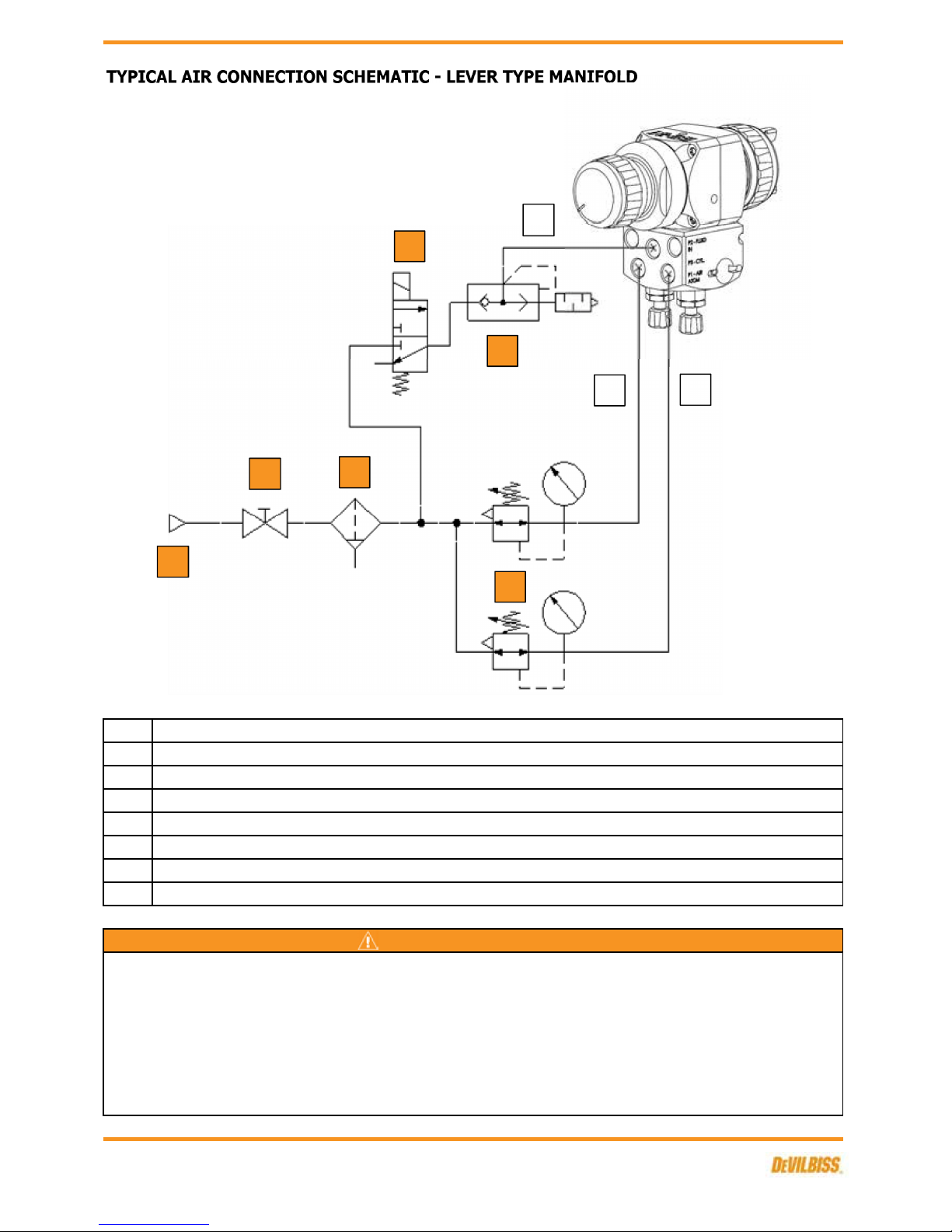
P1
P3
Air regulator & gauge
3/2 solenoid valve, normally closed
Quick exhaust valve & silencer
Air filter
WARNING
CYL - 1/8" G
The spray gun must be earthed to dissipate any electrostatic charges which may be created by fluid or
air flows. This can be achieved through the spray gun mounting, or conductive air/fluid hoses.
Electrical bond from the spray gun to earth should be checked and a resistance of less than 10⁶ Ohms
is required.
CAP - 1/8" G
Compressed air take-off
Shut-off valve
1
2
3
4
5
6
P3
P1
P1
SB-E-2-643 R5.0
7/28
EN
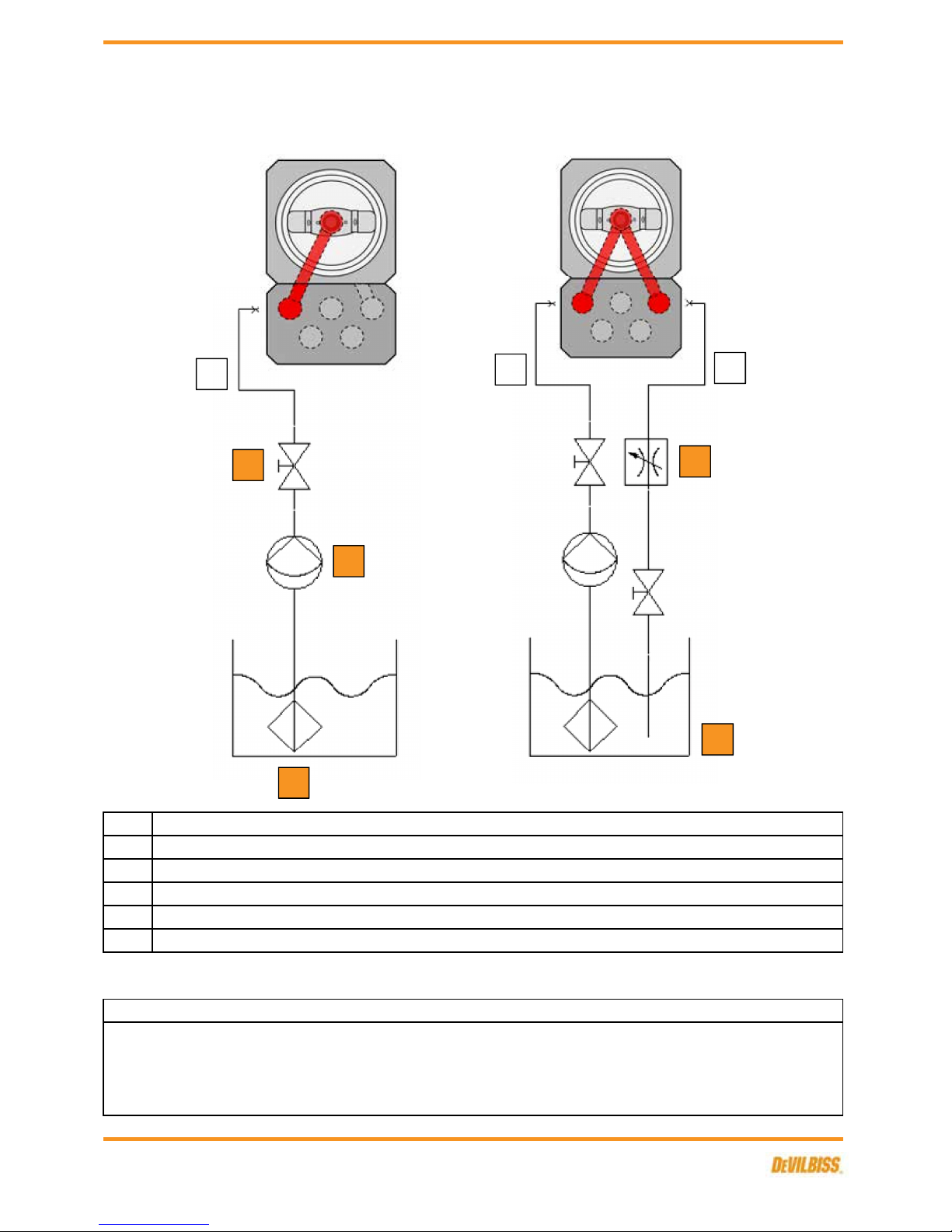
1
2
3
4
5
P2
TYPICAL FLUID CONNECTION SCHEMATIC - LEVER TYPE MANIFOLD
Fluid reservoir
Fluid - 1/8" G
FRONT VIEW FRONT VIEW
AG362U-XXXX-XXXX-L
Protective coatings have been used for storage protection. Flush the equipment fluid passageways
with appropriate solvent before use.
Fluid restrictor valve
Fluid filter
NOTE
AG362-XXXX-XXXX-L
Fluid supply
Shut-off valve
1
2
3
P2
4
5
P2
P2
SB-E-2-643 R5.0
8/28
EN
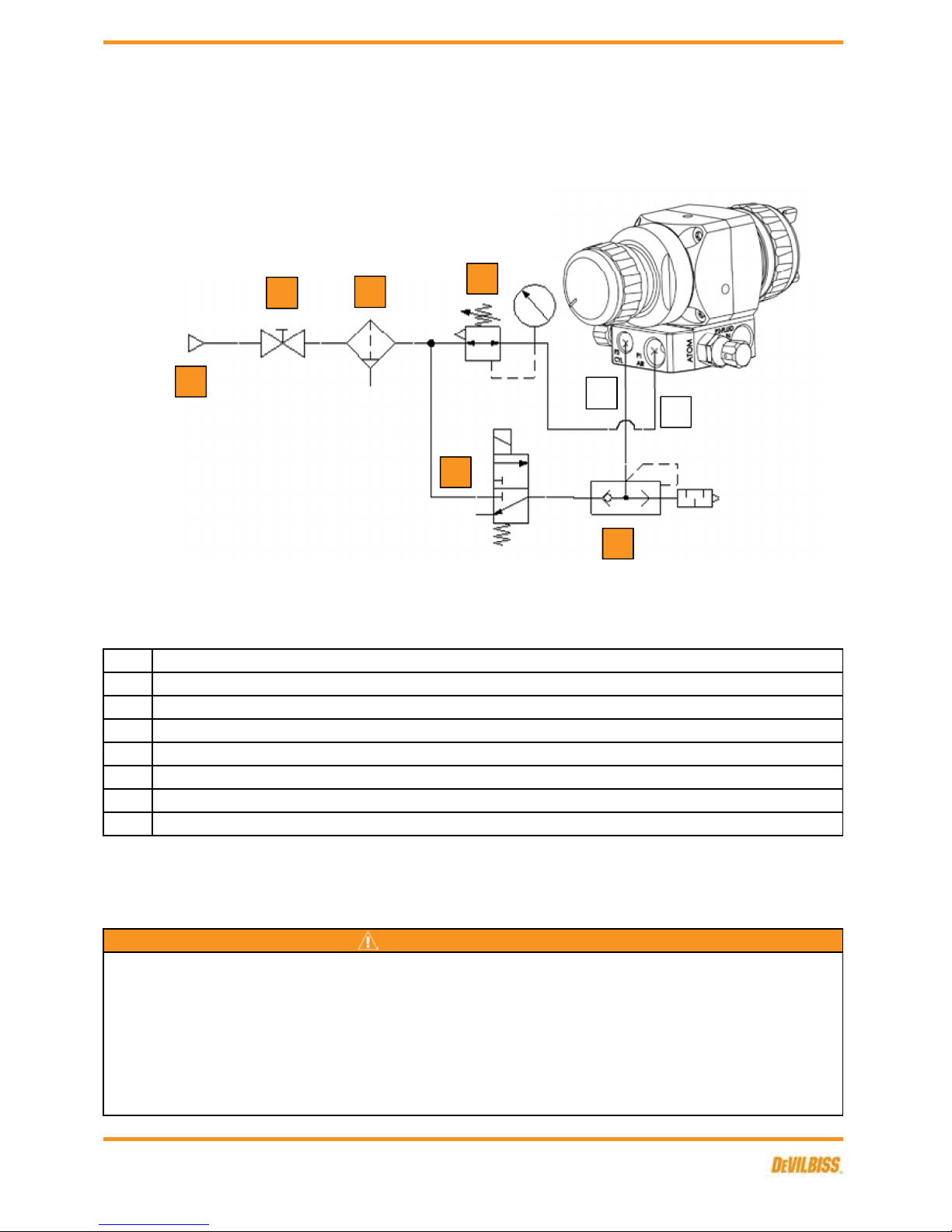
1
2
3
4
5
6
P1
P3
CAP - 1/4" G
CYL - 1/8" G
Air regulator & gauge
TYPICAL AIR CONNECTION SCHEMATIC - SCREW TYPE MANIFOLD
Air filter
WARNING
The spray gun must be earthed to dissipate any electrostatic charges which may be created by fluid or
air flows. This can be achieved through the spray gun mounting, or conductive air/fluid hoses.
Electrical bond from the spray gun to earth should be checked and a resistance of less than 10⁶ Ohms
is required.
Quick exhaust valve & silencer
Compressed air take-off
3/2 solenoid valve, normally closed
Shut-off valve
1
2
3
4
5
6
P3
P1
SB-E-2-643 R5.0
9/28
 Loading...