

Page 1
130516 REGULATOR ASSEMBLY
DESCRIPTION
The self-relieving air pressure regulator is
designed to be a point of use system.
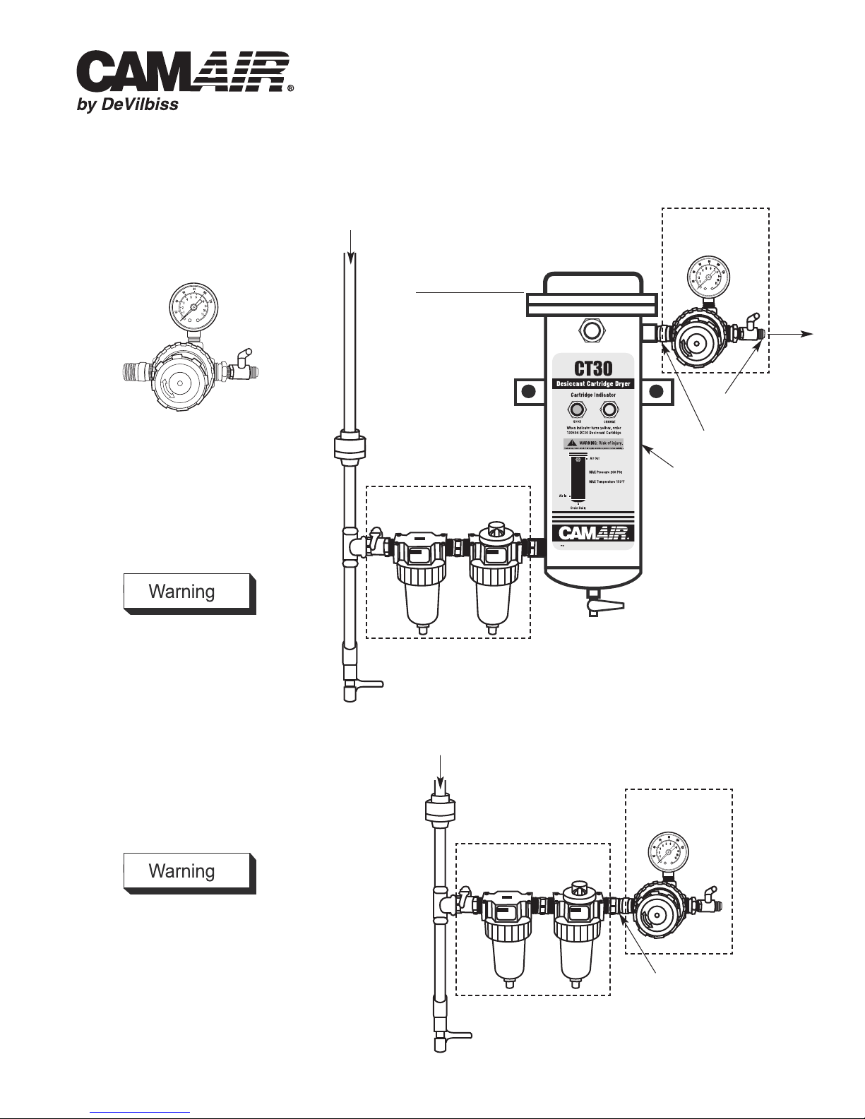
INLET AIR
Service Instruction
SI-6-18-10-A
Replaces SI-6-18-10
RECOMMENDED INSTALLATION INSIDE SPRAY BOOTH
130516
REGULATOR
ASSEMBLY*
54" FROM FLOOR
OUTLET
AIR
1/4 NPSM
SPECIFICATIONS
Air Flow: 75 SCFM @ 100 PSIG inlet
Max. Inlet Pressure: 250 PSIG
Regulated Pressure Range: 2 – 125 PSIG
Max. Temperature: 175°F
INSTALLATION
Max. Temperature: 175°F
RISK OF PERSONAL INJURY
RISK OF PROPERTY DAMAGE
Except as otherwise specified by the manufacturer, this product is specifically
designed for com pressed air service and
use with any other fluid (liquid or gas) is a
misapplication. For example, use with or
injection of certain hazardous gases in the
system (such as oxygen or liquid petroleum
gas) could be harmful to the unit or result in
a combustible condition that may cause fire
or explosion. Manufacturer’s war ranties are
void in the event of misapplication and
manufacturer assumes no responsibility for
any resulting loss.
UNION
OPTIONAL 130515
FILTER ASSEMBLY*
DRAIN
INLET AIR
ALTERNATE INSTALLATION
UNION
1/2 NPT
OPTIONAL
130500
DESICCANT
DRYER*
*Included with 130522
3-Stage System
130516
REGULATOR
ASSEMBLY**
Max. Temperature: 175°F
RISK OF PERSONAL INJURY
Release all air pressure from system
before servicing system. Use only specified parts.
OPTIONAL 130515
FILTER ASSEMBLY**
Remove one nipple
**Included with 130523
2-Stage System
DRAIN
Page 2
Page 2 SI-6-18-10-A
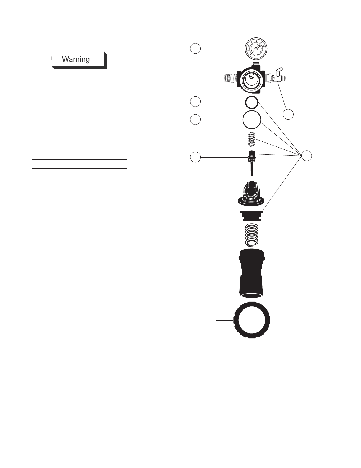
MAINTENANCE
Max. Temperature: 175°F
RISK OF PERSONAL INJURY
Components are under pressure. Relieve
air pressure before performing any maintenance. Rotate regulator knob fully
counter-clockwise to relieve regulator
spring pressure.
PARTS LIST
Ref. Replacement
No. Part No. Description
1 130521 Regulator Kit
2 VA-594 Shut-off Valve
3 GA-288 Gauge
3
*
*
*
*Lightly grease
with enclosed
lubricant
2
1
Handtight
plus 1/4 turn
Page 3
130516 CONJUNTO DEL REGULADOR
DESCRIPCIÓN
El regulador de la presión del aire autodescargante está diseñado para ser un
sistema de punto de uso.
Instrucciones de servicio
SI-6-18-10-A
Substituye SI-6-18-10
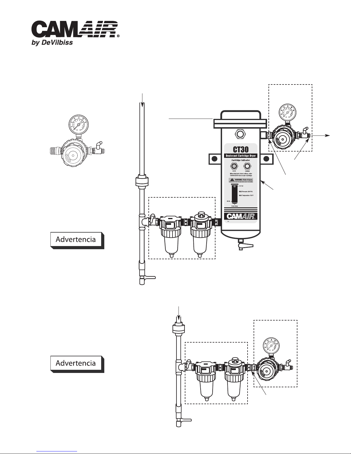
INSTALACIÓN RECOMENDADA DENTRO DEL RECINTO DE PULVERIZACIÓN
AIRE DE ENTRADA
54 PULG. DESDE
EL PISO
130516
CONJUNTO DEL
REGULADOR*
1/4 NPSM
AIRE DE
SALIDA
ESPECIFICACIONES
Circulación del aire: 75 SCFM @ 100 PSIG
de entrada
Presión de entrada máxima: 250 PSIG
Rango de presión regulada: 2 - 125 PSIG
Temperatura máxima: 175°F
INSTALACIÓN
RIESGO DE LESIÓN PERSONAL
RIESGO DE DAÑO A LA PROPIEDAD
Excepto cuando el fabricante especifique
otra cosa, este producto es diseñado
específicamente para servicio con aire
comprimido y su uso con cualquier otro
fluido (líquido o gas) es una aplicación indebida. Por ejemplo, su uso con o la inyección
de ciertos gases peligrosos en el sistema
(tales como oxígeno o gas de petróleo
líquido) puede ser perjudicial para la unidad
o producir una condición combustible que
podría ocasionar incendio o explosión. Las
garantías del fabricante son nulas en caso
de aplicación indebida y el fabricante no
asume ninguna responsabilidad por
ninguna pérdida resultante.
UNIÓN
130515 CONJUNTO DEL
FILTRO* OPCIONAL
DRENAJE
AIRE DE ENTRADA
INSTALACIÓN ALTERNATIVA
UNIÓN
130515 CONJUNTO DEL
FILTRO** OPCIONAL
1/2 NPT
130500
SECADOR
DESECANTE*
OPCIONAL
*Incluido con Sistema de
3 Etapas 130522
130516
CONJUNTO DEL
REGULADOR**
RIESGO DE LESIÓN PERSONAL
Deje escapar toda la presión del aire del
sistema antes de dar servicio de mantenimiento al sistema. Utilice únicamente las
piezas especificadas.
Quite una boquilla
**Incluido con Sistema de
2 Etapas 130523
DRENAJE
Page 4

Página 4 SI-6-18-10-A
MANTENIMIENTO
RIESGO DE LESIÓN PERSONAL
Los componentes se encuentran bajo
presión. Deje escapar la presión del aire
antes de realizar cualquier servicio de
mantenimiento. Haga girar completamente
la perilla del regulador en sentido antihorario
para reducir la presión de resorte.
LISTA DE PIEZAS
Ref. Refacción
No. No. Descripción
1 130521 Kit del regulador
2 VA-594 Válvula de cierre
3 GA-288 Calibrador
3
*
*
*
*Engrase ligeramente con el lubricante adjunto
2
1
Apriete a mano
dando un 1/4 de
vuelta adicional
Page 5

MODULE RÉGULATEUR 130516
DESCRIPTION
Ce régulateur de pression automatique est
conçu comme système de filtration lors de
l'utilisation.
Directions d'entretien
SI-6-18-10-A
Remplace SI-6-18-10
INSTALLATION RECOMMANDÉE À L'INTÉRIEUR DE LA CABINE DE PULVÉRISATION
ENTRÉE D'AIR
137,16 CM (54 PO)
DU PLANCHER
MODULE
RÉGULATEUR
130516*
SORTIE
D'AIR
1/4 NPSM
CARACTÉRISTIQUES
Débit d'air : 75 PI3/MN à 100 PSIG à l'admission
Pression d'admission max. : 250 PSIG
Écart du régulateur de pression : 2 à 125 PSIG
Température max. : 79,44°C (175°F)
INSTALLATION
Max. Temperature: 175°F
DANGER DE BLESSURES
DANGER DE DOMMAGES MATÉRIELS
À l'exception des circonstances indiquées
par le fabricant, ce produit est spécialement
conçu pour fonctionner avec de l'air
comprimé et l'utilisation avec tout autre
substance (liquide ou gazeuse) constitue
une utilisation inappropriée. Par exemple,
toute utilisation ou injection de certains gaz
dangereux dans le système (comme de
l'oxygène ou du gaz de pétrole liquéfié)
risque d'endommager l'appareil ou provoquer une inflammabilité qui peut causer un
incendie ou une explosion. Les garanties du
fabricant sont annulées par toue mauvaise
utilisation et le fabricant ne saurait en
aucun cas être tenu responsable des
dommages provoqués.
UNION
130515 MODULE DU
FILTRE FACULTATIF*
DRAIN
ENTRÉE D'AIR
AUTRE TYPE D'INSTALLATION
RACCORD UNION
130515 MODULE DU
FILTRE FACULTATIF*
1/2 NPT
DESSICCATEUR
D'AIR FACULTATIF
130500*
*Compris avec le système
130522 en 3 étapes
MODULE
RÉGULATEUR
130516**
DANGER DE BLESSURES
Évacuer toute pression d'air du système
avant d'en effectuer l'entretien. Utiliser
uniquement les pièces indiquées.
DRAIN
Retirer un mamelon
**Compris avec le
système 130523 en
2 étapes
Page 6

Page 6 SI-6-18-10-A
ENTRETIEN
DANGER DE BLESSURES
Composants sous pression. Évacuer la
pression d'air avant d'effectuer l'entretien.
Faire pivoter le bouton du régulateur dans
le sens contraire des aiguilles d'une
montre jusqu'au bout afin de libérer la
pression du ressort de régulateur.
LISTE DES PIÈCES
Nº de
No de pièce
réf. détachée Description
1 130521
2 VA-594 Robinet d'arrêt
3 GA-288 Manomètre
Trousse de régulateur
3
*
*
*
*Graisser légèrement
avec le lubrifiant
fourni
2
1
Resserrer à
la main plus
1/4 de tour.
Page 7

NOTES / NOTAS
Page 7SI-6-18-10-A
Page 8

Page 8 SI-6-18-10-A
GARANTÍA
Este producto está cubierto por la garantía limitada de un año de DeVilbiss.
Lista de Ventas y Servicios de DeVilbiss en todo el mundo: www.autorefinishdevilbiss.com
Repintado automotriz de DeVilbiss
eVilbiss tiene distribuidores autorizados en todo el mundo. Para
D
equipos, repuestos y servicio de mantenimiento, consulte las Páginas
Amarillas bajo “Equipos y suministros para talleres de repintado auto-
otriz” Para asistencia técnica, consulte la lista abajo.
m
ficina de Servicio al Cliente en EE.UU./Canadá
O
11360 S. Airfield Road, Swanton, OH 43558
Teléfono gratuito: 1-800-445-3988 (EE.UU. y Canadá únicamente)
ax gratuito: 1-800-445-6643
F
©2012 DeVilbiss Todos los derechos reservados. Impreso en EE.UU.
GARANTIE
Ce produit est couvert par la garantie limitée d'un an de DeVilbiss.
Liste des distributeurs et réparateurs DeVilbiss à travers le monde : www.autorefinishdevilbiss.com
Remise à neuf de carrosseries DeVilbiss
On trouve des distributeurs autorisés DeVilbiss à travers le monde.
Pour se procurer du matériel et des pièces, ou pour de l'entretien,
consulter la rubrique « Automobile - Réparation de carrosserie et peinture » des Pages Jaunes. Pour assistance technique, voir ci-dessous.
Communiquer avec le service à la clientèle pour le Canada et
les États-Unis au :
11360 S. Airfield Road, Swanton, OH 43558
Téléphone sans frais : 1-800-445-3988 (États-Unis et Canada seulement).
Télécopieur sans frais : 1-800-445-6643
WARRANTY
This product is covered by DeVilbiss' 1 Year Limited Warranty.
©2012 DeVilbiss Tous droits réservés. Imprimé aux États-Unis.
DeVilbiss Worldwide Sales and Service Listing: www.autorefinishdevilbiss.com
DeVilbiss Automotive Refinishing
DeVilbiss has authorized distributors throughout the world.
For equipment, parts and service, check the Yellow Pages
under “Automotive Body Shop Equipment and Supplies.”
For technical assistance, see listing below.
U.S./Canada Customer Service Office:
11360 S. Airfield Road, Swanton, OH 43558
Toll-Free Telephone: 1-800-445-3988 (U.S.A. and Canada only)
Toll-Free Fax: 1-800-445-6643
8/12 ©2012 DeVilbiss All rights reserved. Printed in U.S.A.
 Loading...