

Page 1
INSTRUCTION MANUAL
VARIFOCAL DOME CAMERA
MD3CL12H4-9 Color NSTC Hi Resolution DC12V
MD3CL12M Color NTSC STD Resolution DC12V
FEATURES
Compact and Light weight design.
Integrated 4-9mm Vari-focal Direct Drive Lens allows
for Easy installation and adjustments.
Hi-speed F1.6 Iris provides excellent low light
performance.
DSP controls for Back Light Compensation, White
Balance, and Gain Control .
Manual pan/ tilt mechanism.
Can be installed on a wall or a ceiling.
Video cable with BNC included.
PRECAUTIONS
1. Do not attempt to disassemble the camera. To prevent electric
shock, do not remove screws or cover. There are no user
serviceable parts inside. Refer servicing to qualified service
personnel.
2. Handle the camera with care. Do not abuse the camera. Avoid
striking or shaking it. Improper handling or storage could damage
the camera.
3. Do not expose the camera to rain or moisture, or try to operate it in
wet areas. Do take immediate action if ever the camera does
become wet. Turn power off and refer servicing to qualified service
personnel. Moisture can damage the camera and also create the
danger of electric shock.
4. Never face the camera toward the sun. Irrespective of whether the
camera is in use or not, it should never face it toward the sun. Do
use cautiously when operating the camera in the vicinity of
spotlights or other bright lights and light reflecting objects.
5. Do not operate the camera beyond its temperature, humidity or
power source ratings. Do not use the camera in an extreme
environment such as high temperature or humidity. Use the camera
under conditions where temperatures are within –5℃ ~ + 45℃, and
humidity is below 80%.
6. Do not touch the CCD sensor directly with your fingers. If necessary,
use soft cloth moistened with alcohol to wipe off the dust.
7. When the camera is not in use, ensure the lens is kept properly in
place to protect the CCD sensor.
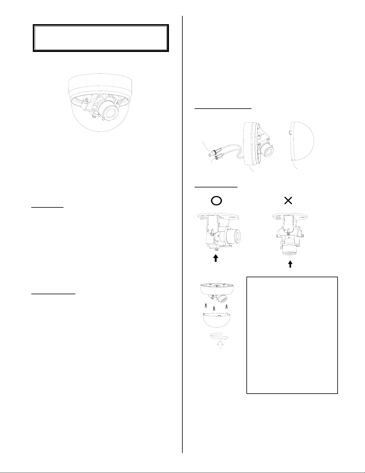
PART DESCRIPTION
Coaxial video cable
DC jack power
BubbleCamera body
INSTALLATION
Cover Removal and Attachment
To remove the bubble, rotate counter
clockwise and pull lightly. To attach it,
put inner cover into bubble, align lens
into the slo t of inner cover, then insert
bubble into camera body and rotate
clockwise lightly until it snaps
together.
When removing the camera and
gimble from chassis, make sure the
slot is parallel with base. Pull and
insert lightly.
1. Creating a Hole in the Ceiling or Wall
Make three holes fo r th e sc r e ws a ffixing the camera bod y , an d
additional one hole for the power and video cables. Use the
supplied template to mark the appropriate mounting position on the
ceiling or the wall.
P1
If wall mounting remove the bubble as
above, after taking the camera and
gimble from the chassis remove the
camera from the gimble and turn
through 90° and replace. (TOP of
camera is indicated on camera cradle).
P2
Page 2
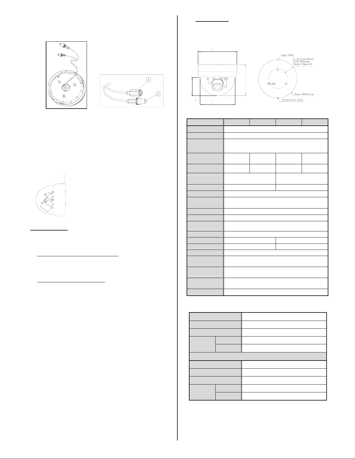
2. Connecting the Cables
Please refer to the diagrams below.
1 Connect the power to the DC Jack.
2 Connect the video cable from monitor to the equipped video cable .
ATTENTION
1. Check if the power is off before handing the power cable.
2. Check for proper polarity before connecting to power supply.
Improper polarity may cause damage to the camera.
3. Mounting the Camera Body
Remove the body cover, and mount the camera body to the
ceiling or wall. Align the housing to the holes you have made, and
use three screws to mount the camera body.
Choose screws suitable for the type of ceiling
or wall material, Screws with a diameter of 4
to 5 mm are recommended.
ADJUSTMENT
1. Setting the Dip Switch
Set according to lighting conditions Dip Switch for BLC & AGC
functions.
z Back Light Compensation (BLC) ON/ OFF :
When strong, unwanted background lighting interferes with the
clarity of important areas, turn this switch to the “ON” position.
The BLC compensates to back light conditions in the central area.
z Auto Gain Control (AGC) ON / OFF:
Switching the AGC on will improve camera sensitivity in low light
conditions.
2. Adjusting the Camera Direction
Camera body moves in two ways: Pan, and Tilt.
Adjust the direction so that the lens is aiming at the target.
3. Adjusting the View Angle and Focus
Use the lever to adjust the view angle and focus.
4. Adjusting the DC Iris Level
Set according to lighting conditions.
a). Turn the dipswitch Auto Gain Control (AGC) to OFF.
b). Adjust the DC iris level. Please adjust with care so as not cause
damage to the potentiometer.
c). Turn the dipswitch Auto Gain Control (AGC) to ON.
5. Completing the Adjustment and Installation
a). Attach the body cover.
b). Turn the inner cover to position the lens to the opening.
Attach the dome cover.
Packing List
1. Dome Camera with D.D. Vari-focal Lens x 1
2. Instruction Manual x 1
3. Template x 1
100Omm
m
m
7
4
O
90mm
CAMERA SPECIFICATIONS:
Model No. MD3CL12H4-9 MD3CL12M
Video Process
Scanning Element 2 :1 Interlace / H :15.750KHz , V : 59.94Hz
Image Picture
Element
Effective Picture
Element
Resolution
Minimum
Illumination
S/N Ratio ≧ 48dB(AGC OFF) ≧ 52dB(AGC OFF)
Bubble Tint Colored ; Optical perfect Max. 1F loss
Backlight
Compensation
AGC On / Off Switch
Sync System Internal
Gamma
Compensation
Video Output 1.0Vpp, 75 ohm Unbalanced
White Balance Automatic White Balance -----
ATW Range 2700K – 9100K -----
Power Range DC12V ±10%
Power
Consumption
Operation
Temperature
Overall Camera
Dimensions
Weights 180g (6.35 ounces) Net.
LENS SPECIFICATION:
Focal length 4.0 - 9.0mm
Maximum aperture ratio 1 : 1.6
Iris T : F2.4 – 360 W : F1.6 ~ 360
Angle of View
Option Lens
Focal length 2.6 - 6.0mm
Maximum aperture ratio 1 : 1.6
Iris T : F2.3 – 360 W : F1.6 ~ 360
Angle of View
Note. Specification subject to change without notice.
P3
m
m
0
8
DSP, CXD2163BR (SONY SS-1M)
1/3” High Sensitivity CCD
768(H) x 494(V) 510(H) x 492(V)
480 Horizontal
TV Lines
0.8Lux @F1.2/ 1.5 Lux @F1.6 0.3Lux @F1.2/ 0.5 Lux @F1.6
Height 80mm (3.15”) Diameter 100mm (3.94”)
Horizontal 71°( Wide ) – 31.6°( Tele )
Vertical 51.8°( Wide) – 23.6°( Tele )
Horizontal 106 ( Wide ) – 47.6°( Tele )
Vertical 78.2 °( Wide) – 35.8 °( Tele )
On ( Central Area ) / Off Switch
0.45
2.8W ( Max )
-5°C to ~ +45°C
Less than 80% R.H.
Version Nr. : 20030731-01A
400 Horizo ntal
TV Lines
Part No:531-D0005-000
Page 3

P4
 Loading...