

De Vielle DEF963739, DEF963739/CH-09FLCD Instruction Manual
INSTRUCTION MANUAL
Model: DEF963739
PLEASE RETAIN THIS MANUAL FOR FUTURE REFERENCE
LCD Convector Heater
2300W
2
THE HEATER CAN BE FREE STANDING OR WALL MOUNTED.
FOR ASSEMBLY INSTRUCTIONS SEE BELOW:
FREE STANDING
WALL MOUNTING THE HEATER
Caution:
- There should be a distance of at least 50cm between the lower part of the
appliance and the oor.
- There should be a distance of at least 1 metre between the upper part of the
appliance and the ceiling.
- The feet must be removed before mounting the appliance on the wall.
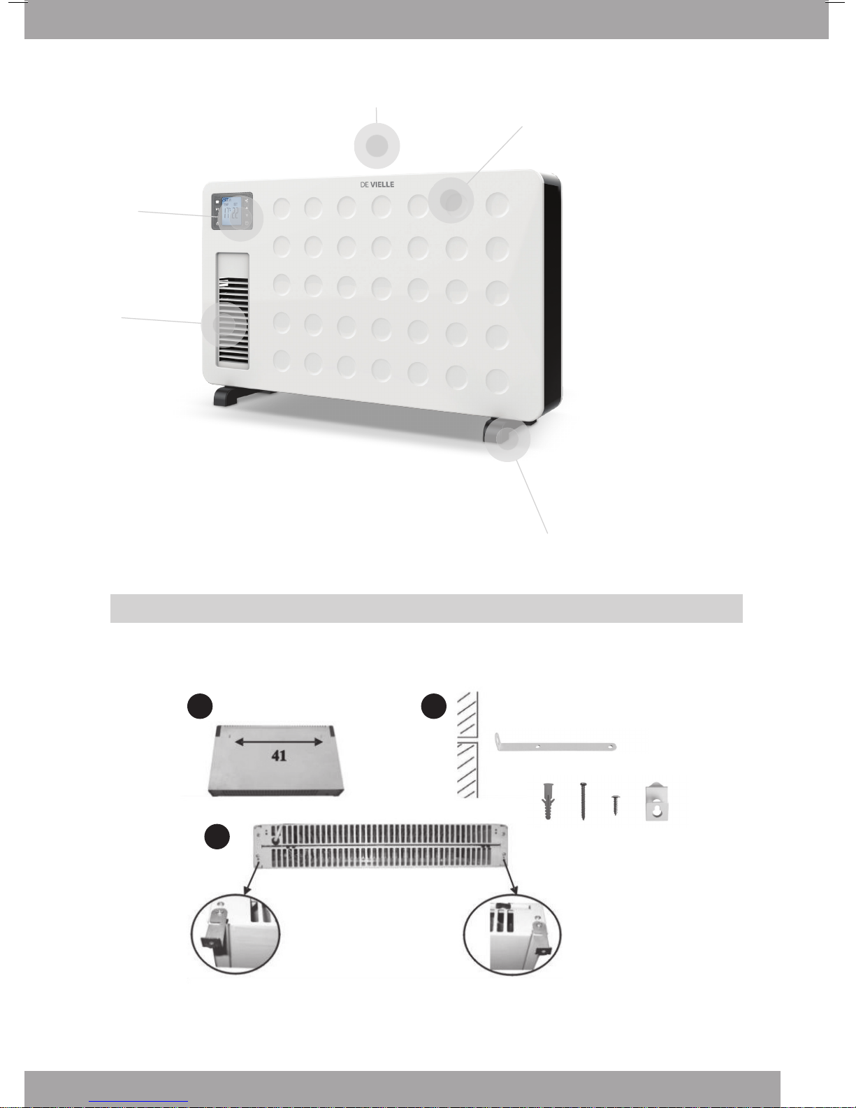
1. Measure the distance between the two slots situated at the back of the appliance
(see picture A)
2. Drill two holes at the same distance in the wall and insert a plug in each hole you just drilled. Place
the brackets facing the holes as indicated on picture B and attach them in this position with the
screws supplied.
3. Before attaching the appliance on the brackets, attach the two other brackets underneath the
appliance as indicated on picture C.
4. Attach the appliance on the wall. To do so, hold it in such way that the slots are facing the brackets;
insert the appliance halfway onto the brackets until the appliance can go down into the grooves of
the brackets.
5. As soon as the appliance is positioned correctly, take a pencil and mark a dot in the hole of each
bracket situated underneath the appliance.
6. Then take o the appliance by proceeding the other way around compared to point 4 above.
7. Drill a hole in the wall on each dot you just marked and insert a plug in each hole.
8. Attach the appliance back on the wall as indicated in point 4, insert screws through the brackets
underneath the appliance and tighten without forcing.
Assembly Of The Heater
Components
ASSEMBLY
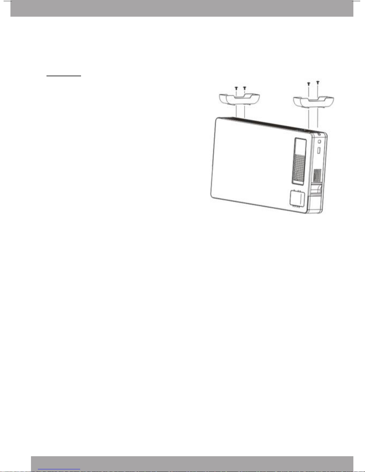
Before using the heater, the feet (supplied
separately in the carton), must be fitted to the unit.
The screw pack to attach the feet to your heater will
be taped to either one of the feet for your heater, or
taped to the plug.
Carefully turn the Main Body upside-down on a scratchfree and stable surface. Be careful to prevent damage
to the cosmetic finish or your floor surfacing.
Each foot requires two screws to attach them securely
to the heater. Two holes are pre-drilled in each foot and
in the base of the heater. Align the feet with the holes,
insert the screws and use a screwdriver to secure the
feet to the base of the heater. Return to upright position.
Feet x2
Screws x4Main Body x1
WARNING: Operate the heater in the normal
upright position only with the feet attached to the
bottom. Any other position could create a
hazardous situation.
3
WALL MOUNTING
A B
C
1
4
5
2
3
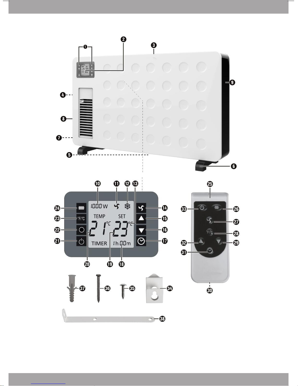
1 Front Cover
2 Display
3 Turbo
4 Rear Cover
5 Feet
x4 x4 x4 x2
x2
4
Assembly Of The Heater
 Loading...