

Page 1

DEVELOP
SERVICE MANUAL
THEORY OF OPERATION
QC 2235plus
Page 2

Page 3
QC 2235plus Field Service Ver1.0 Mar. 2004 SAFETY AND IMPORTANT WARNING
SAFETY AND IMPORTANT WARNING ITEMS
Read carefully the Safety and Important Warning Items described below to understand
them before doing service work.
IMPORTANT NOTICE
Because of possible hazards to an inexperienced person servicing this product as well as
the risk of damage to the product, Develop GmbH. (hereafter called the Develop) strongly
recommends that all servicing be performed only by Develop-trained service technicians.
Changes may have been made to this product to improve its performance after this Service
Manual was printed. Accordingly, Develop does not warrant, either explicitly or implicitly,
that the information contained in this Service Manual is complete and accurate.
The user of this Service Manual must assume all risks of personal injury and/or damage to
the product while servicing the product for which this Service Manual is intended.
Therefore, this Service Manual must be carefully read before doing service work both in the
course of technical training and even after that, for performing maintenance and control of
the product properly.
Keep this Service Manual also for future service.
DESCRIPTION ITEMS FOR DANGER, WARNING AND CAUTION
In this Service Manual, each of three expressions " DANGER", " WARNING", and
" CAUTION" is defined as follows together with a symbol mark to be used in a limited
meaning.
When servicing the product, the relevant works (disassembling, reassembling, adjustment,
repair, maintenance, etc.) need to be conducted with utmost care.
DANGER: Action having a high possibility of suffering death or serious injury
WARNING: Action having a possibility of suffering death or serious injury
CAUTION: Action having a possibility of suffering a slight wound, medium
Symbols used for safety and important warning items are defined as follows:
:Precaution when servicing the
product.
:Prohibition when servicing the
product.
:Direction when servicing the
product.
trouble, and property damage
General
precaution
General
prohibition
General
instruction
S-1
Electric hazard High temperature
Do not touch
with wet hand
Unplug Ground/Earth
Do not
disassemble
Page 4
SAFETY AND IMPORTANT WARNING ITEMS QC 2235plus Field Service Ver1.0 Mar.
SAFETY WARNINGS
[1] MODIFICATIONS NOT AUTHORIZED BY DEVELOP GMBH
Develop brand products are renowned for their high reliability. This reliability is achieved
through high-quality design and a solid service network.
Product design is a highly complicated and delicate process where numerous mechanical,
physical, and electrical aspects have to be taken into consideration, with the aim of arriving
at proper tolerances and safety factors. For this reason, unauthorized modifications involve
a high risk of degradation in performance and safety. Such modifications are therefore
strictly prohibited. the points listed below are not exhaustive, but they illustrate the reasoning behind this policy.
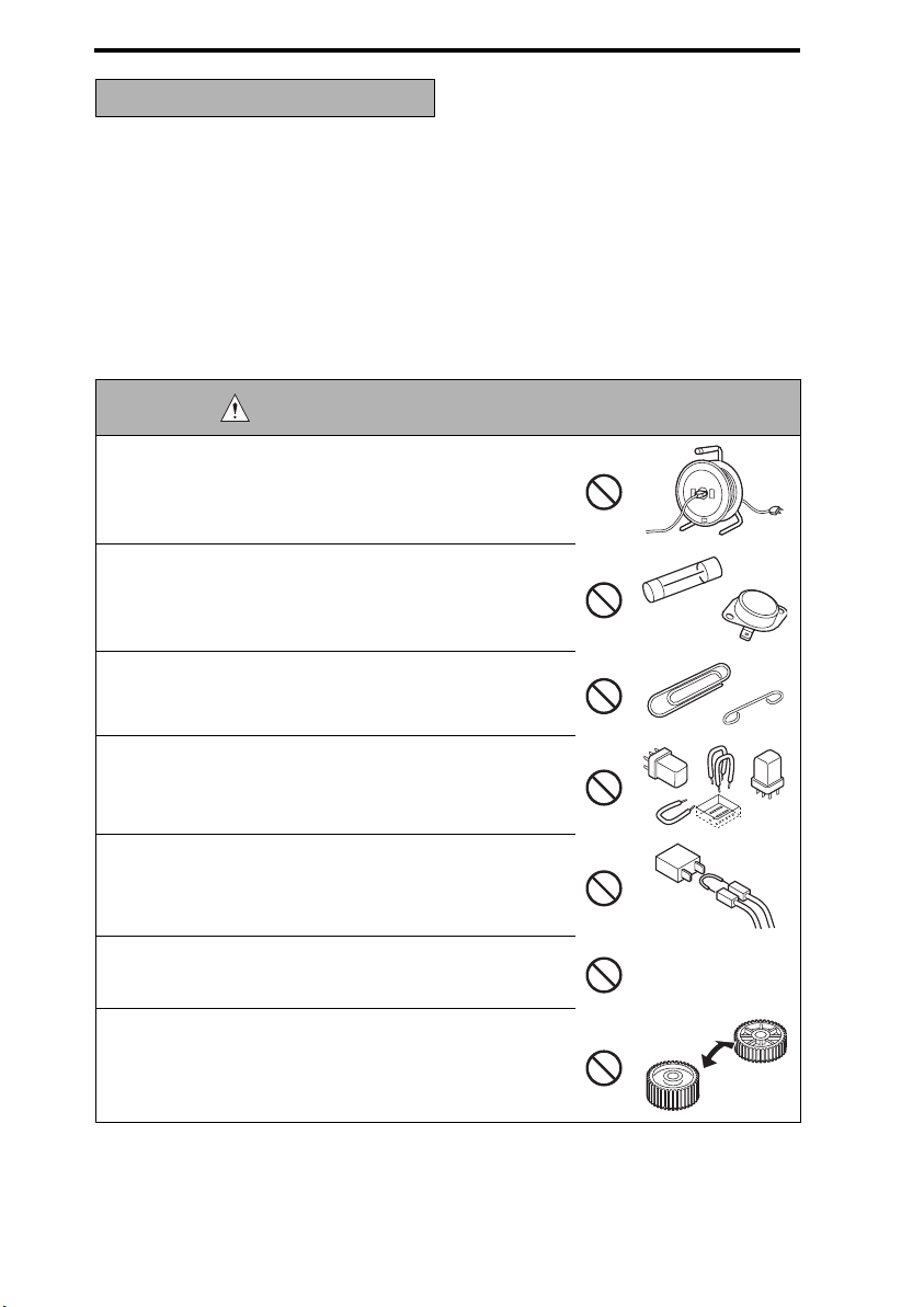
DANGER : PROHIBITED ACTIONS
• Using any cables or power cord not specified by Develop.
• Using any fuse or thermostat not specified by Develop.
Safety will not be assured, leading to a risk of fire and
injury.
• Disabling fuse functions or bridging fuse terminals with
wire, metal clips, solder or similar object.
• Disabling relay functions (such as wedging paper between
relay contacts)
• Disabling safety functions (interlocks, safety circuits, etc.)
Safety will not be assured, leading to a risk of fire and
injury.
• Making any modification to the product unless instructed
by Develop
• Using parts not specified by Develop
S-2
Page 5
QC 2235plus Field Service Ver1.0 Mar. 2004 SAFETY AND IMPORTANT WARNING
[2] CHECKPOINTS WHEN PERFORMING ON-SITE SERVICE
Develop brand products are extensively tested before shipping, to ensure that all applicable
safety standards are met, in order to protect the customer and customer engineer (hereafter called the CE) from the risk of injury. However, in daily use, any electrical equipment
may be subject to parts wear and eventual failure. In order to maintain safety and reliability,
the CE must perform regular safety checks.
1. Power Supply
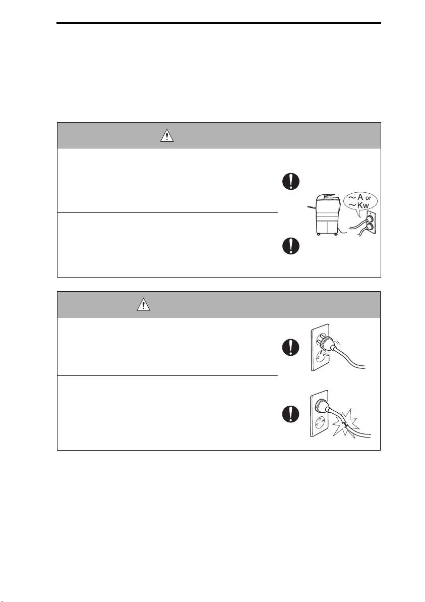
WARNING: Wall Outlet
• Check that mains voltage is as specified. Plug the power
cord into the dedicated wall outlet with a capacity greater
than the maximum power consumption.
If excessive current flows in the wall outlet, fire may
result.
• If two or more power cords can be plugged into the wall
outlet, the total load must not exceed the rating of the wall
outlet.
If excessive current flows in the wall outlet, fire may
result.
WARNING: Power Plug and Cord
• Make sure the power cord is plugged in the wall outlet
securely.
Contact problems may lead to increased resistance,
overheating, and the risk of fire.
• Check whether the power cord is damaged. Check
whether the sheath is damaged.
If the power plug, cord, or sheath is damaged, replace
with a new power cord (with plug and connector on each
end) specified by Develop. Using the damaged power
cord may result in fire or electric shock.
S-3
Page 6
SAFETY AND IMPORTANT WARNING ITEMS QC 2235plus Field Service Ver1.0 Mar.
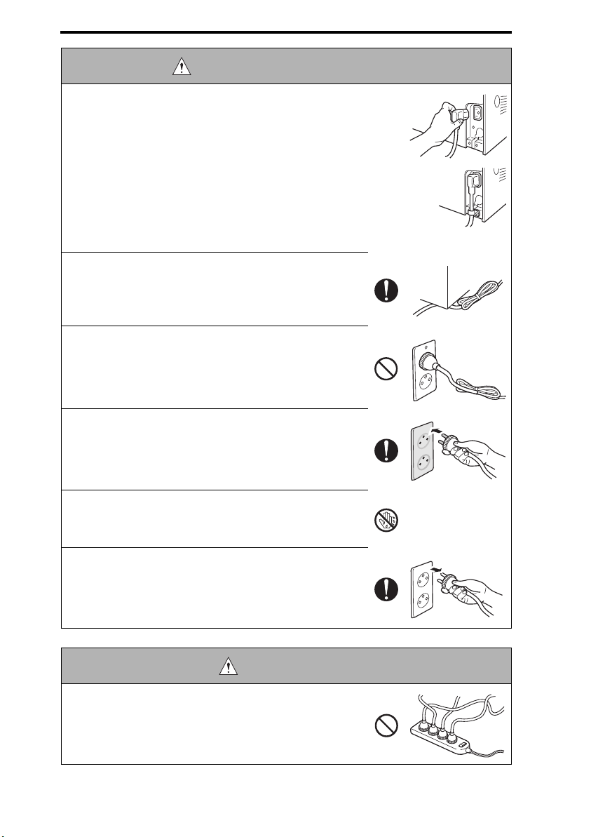
WARNING: Power Plug and Cord
• When using the power cord (inlet type) that came with this
product, be sure to observe the following precautions:
a. Make sure the connector is securely inserted in the inlet
on the rear panel of the product.
Secure the cord with a fixture properly.
b. If the power cord or sheath is damaged, replace with a
new power cord (with plugs on both ends) specified by
Develop.
If the power cord (inlet type) is not connected to the
product securely, a contact problem may lead to
increased resistance, overheating, and risk of fire.
• Check whether the power cord is not stepped on or
pinched by a table and so on.
Overheating may occur there, leading to a risk of fire.
• Do not bundle or tie the power cord.
Overheating may occur there, leading to a risk of fire.
• Check whether dust is collected around the power plug
and wall outlet.
Using the power plug and wall outlet without removing
dust may result in fire.
• Do not insert the power plug into the wall outlet with a wet
hand.
The risk of electric shock exists.
• When unplugging the power cord, grasp the plug, not the
cable.
The cable may be broken, leading to a risk of fire and
electric shock.
WARNING: Wiring
• Never use multi-plug adapters to plug multiple power cords
in the same outlet.
If used, the risk of fire exists.
S-4
Page 7
QC 2235plus Field Service Ver1.0 Mar. 2004 SAFETY AND IMPORTANT WARNING
WARNING: Wiring
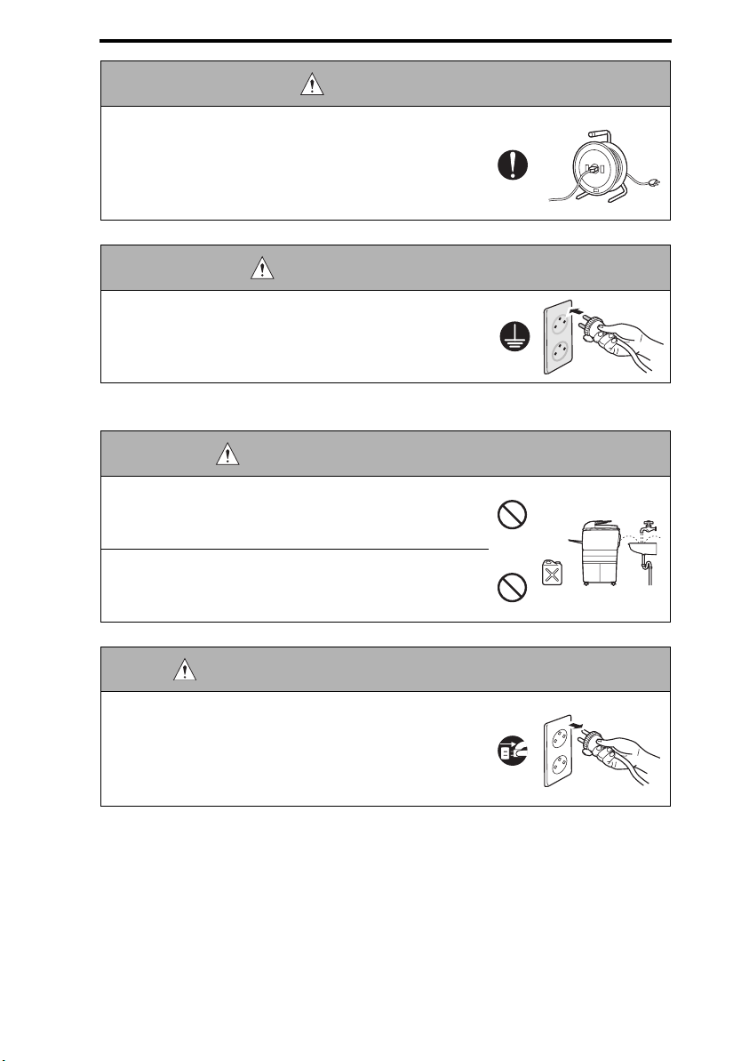
• When an extension cord is required, use a specified one.
Current that can flow in the extension cord is limited, so
using a too long extension cord may result in fire.
Do not use an extension cable reel with the cable taken
up. Fire may result.
WARNING: Ground connection
• Check whether the product is grounded properly.
If current leakage occurs in an ungrounded product, you
may suffer electric shock while operating the product.
Connect power plug to grounded wall outlet.
2. Installation Requirements
WARNING: Prohibited Installation Place
• Do not place the product near flammable materials or volatile materials that may catch fire.
A risk of fire exists.
• Do not place the product in a place exposed to water such
as rain.
A risk of fire and electric shock exists.
WARNING: When not using product for a long time
• When the product is not used over an extended period of
time (holidays, etc.), switch it off and unplug the power
cord.
Dust collected around the power plug and outlet may
cause fire.
S-5
Page 8

SAFETY AND IMPORTANT WARNING ITEMS QC 2235plus Field Service Ver1.0 Mar.
CAUTION: Ventilation
• The product generates ozone gas during operation, but it
will not be harmful to the human body.
If a bad smell of ozone is present in the following cases,
ventilate the room.
a. When the product is used in a poorly ventilated room
b. When taking a lot of copies
c. When using multiple products at the same time
CAUTION: Fixing
• Be sure to lock the caster stoppers.
In the case of an earthquake and so on, the product may
slide, leading to a injury.
CAUTION: Inspection before Servicing
• Before conducting an inspection, read all relevant documentation (service manual, technical notices, etc.) and
proceed with the inspection following the prescribed procedure, using only the prescribed tools. Do not make any
adjustment not described in the documentation.
If the prescribed procedure or tool is not used, the product may break and a risk of injury or fire exists.
• Before conducting an inspection, be sure to disconnect
the power plugs from the product and options.
When the power plug is inserted in the wall outlet, some
units are still powered even if the POWER switch is
turned OFF. A risk of electric shock exists.
• The area around the fixing unit is hot.
You may get burnt.
S-6
Page 9
QC 2235plus Field Service Ver1.0 Mar. 2004 SAFETY AND IMPORTANT WARNING
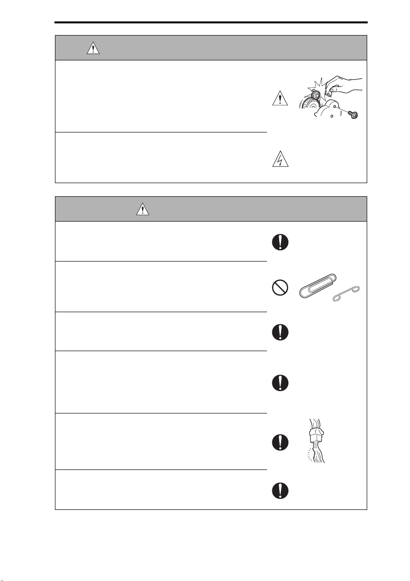
WARNING: Work Performed with the product Powered
• Take every care when making adjustments or performing
an operation check with the product powered.
If you make adjustments or perform an operation check
with the external cover detached, you may touch live or
high-voltage parts or you may be caught in moving gears
or the timing belt, leading to a risk of injury.
• Take every care when servicing with the external cover
detached.
High-voltage exists around the drum unit. A risk of electric shock exists.
WARNING: Safety Checkpoints
• Check the exterior and frame for edges, burrs, and other
damages.
The user or CE may be injured.
• Do not allow any metal parts such as clips, staples, and
screws to fall into the product.
They can short internal circuits and cause electric shock
or fire.
• Check wiring for squeezing and any other damage.
Current can leak, leading to a risk of electric shock or
fire.
• Carefully remove all toner remnants and dust from electrical parts and electrode units such as a charging corona
unit.
Current can leak, leading to a risk of product trouble or
fire.
• Check high-voltage cables and sheaths for any damage.
Current can leak, leading to a risk of electric shock or
fire.
• Check electrode units such as a charging corona unit for
deterioration and sign of leakage.
Current can leak, leading to a risk of trouble or fire.
S-7
Page 10
SAFETY AND IMPORTANT WARNING ITEMS QC 2235plus Field Service Ver1.0 Mar.
WARNING: Safety Checkpoints
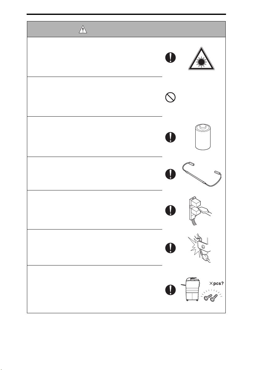
• Before disassembling or adjusting the write unit (P/H unit)
incorporating a laser, make sure that the power cord has
been disconnected.
The laser light can enter your eye, leading to a risk of
loss of eyesight.
• Do not remove the cover of the write unit. Do not supply
power with the write unit shifted from the specified mounting position.
The laser light can enter your eye, leading to a risk of
loss of eyesight.
• When replacing a lithium battery, replace it with a new lithium battery specified in the Parts Guide Manual. Dispose
of the used lithium battery using the method specified by
local authority.
Improper replacement can cause explosion.
• After replacing a part to which AC voltage is applied (e.g.,
optical lamp and fixing lamp), be sure to check the installation state.
A risk of fire exists.
• Check the interlock switch and actuator for loosening and
check whether the interlock functions properly.
If the interlock does not function, you may receive an
electric shock or be injured when you insert your hand in
the product (e.g., for clearing paper jam).
• Make sure the wiring cannot come into contact with sharp
edges, burrs, or other pointed parts.
Current can leak, leading to a risk of electric shock or
fire.
• Make sure that all screws, components, wiring, connectors, etc. that were removed for safety check and maintenance have been reinstalled in the original location. (Pay
special attention to forgotten connectors, pinched cables,
forgotten screws, etc.)
A risk of product trouble, electric shock, and fire exists.
S-8
Page 11
QC 2235plus Field Service Ver1.0 Mar. 2004 SAFETY AND IMPORTANT WARNING
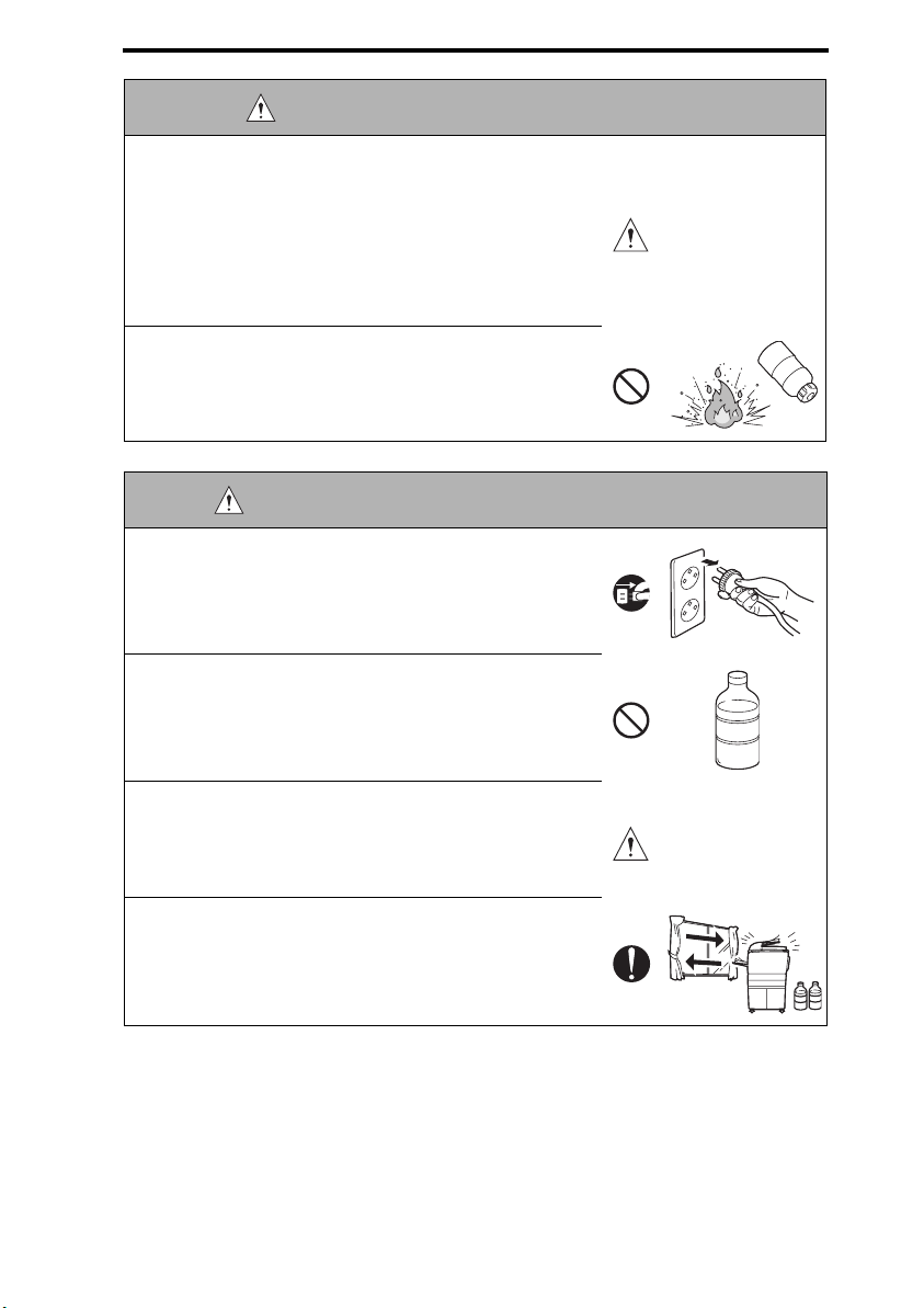
WARNING: HANDLING OF CONSUMABLE
• Toner and developer are not harmful substances, but care
must be taken not to breathe excessive amounts or let the
substances come into contact with eyes, etc. It may be
stimulative.
If the substances get in the eye, rinse with plenty of water
immediately. When symptoms are noticeable, consult a
physician.
• Never throw the used cartridge and toner into fire.
You may be burned due to dust explosion.
CAUTION: HANDLING OF SERVICE MATERIALS
• Unplug the power cord from the wall outlet.
Drum cleaner (isopropyl alcohol) and roller cleaner (acetone-based) are highly flammable and must be handled
with care. A risk of fire exists.
• Do not replace the cover or turn the product ON before
any solvent remnants on the cleaned parts have fully
evaporated.
A risk of fire exists.
• Use only a small amount of cleaner at a time and take
care not to spill any liquid. If this happens, immediately
wipe it off.
A risk of fire exists.
• When using any solvent, ventilate the room well.
Breathing large quantities of organic solvents can lead to
discomfort.
S-9
Page 12

SAFETY AND IMPORTANT WARNING ITEMS QC 2235plus Field Service Ver1.0 Mar.
[3] MEASURES TO TAKE IN CASE OF AN ACCIDENT
1. If an accident has occurred, the distributor who has been notified first must immediately take emergency measures to provide relief to affected persons and to prevent
further damage.
2. If a report of a serious accident has been received from a customer, an on-site evaluation must be carried out quickly and Develop must be notified.
3. To determine the cause of the accident, conditions and materials must be recorded
through direct on-site checks, in accordance with instructions issued by Develop.
[4] CONCLUSION
1. Safety of users and customer engineers depends highly on accurate maintenance and
administration. Therefore, safety can be maintained by the appropriate daily service
work conducted by the customer engineer.
2. When performing service, each product on the site must be tested for safety. The customer engineer must verify the safety of parts and ensure appropriate management of
the equipment.
[5] FUSE
CAUTION
Double pole / neutral fusing
ATTENTION
Double pôle / fusible sur le neutre.
[6] LED Radiation Safety
• This product is a copier which operates by means of a LED (light emitting diodes) expo-
sure system. There is no possibility of danger from the LED optical radiation, because
the LED optical radiation level dose not exceed the accessible radiation limit of class 1
under all conditions of operation, maintenance, service and failure.
S-10
Page 13
QC 2235plus Field Service Ver1.0 Mar. 2004 SAFETY AND IMPORTANT WARNING
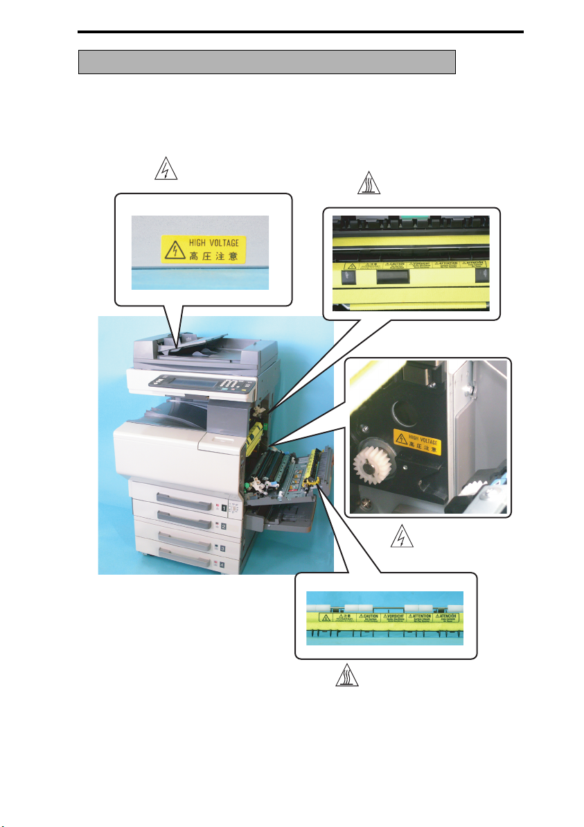
INDICATION OF WARNING ON THE MACHINE
Caution labels shown are attached in some areas on/in the machine.
When accessing these areas for maintenance, repair, or adjustment, special care should
be taken to avoid burns and electric shock.
High voltage
High temperature
S-11
High voltage
High temperature
4036fsS001c0
Page 14
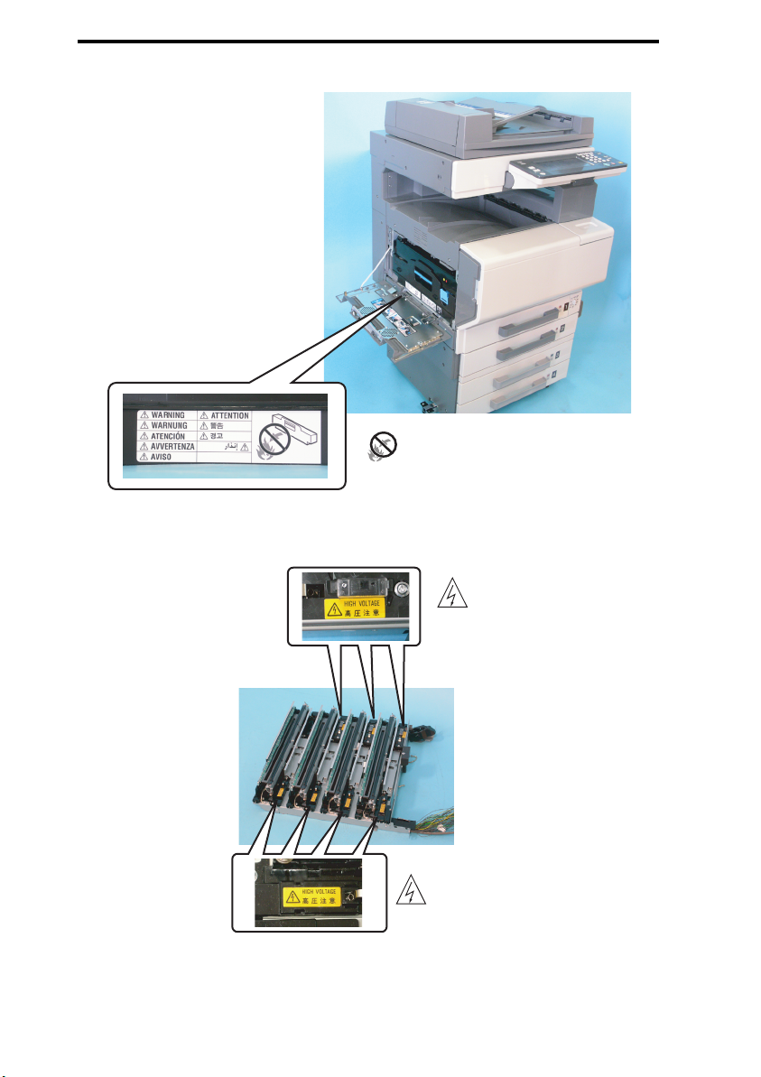
SAFETY AND IMPORTANT WARNING ITEMS QC 2235plus Field Service Ver1.0 Mar.
Do not throw into a fire
4036fsS002c0
S-12
High voltage
High voltage
4036fsS003c0
Page 15

DEVELOP
SERVICE MANUAL
THEORY OF OPERATION
QC 2235plus
Main Unit
Page 16

Page 17

QC 2235plus Theory of Operation Ver1.0 Mar. 2004
CONTENTS
IOutline
1. System configuration............................................................................................1-1
2. Product specifications ..........................................................................................1-3
2.1 Type ...................................................................................................................1-3
2.2 Functions...........................................................................................................1-3
2.3 Types of paper ...................................................................................................1-4
2.4 Maintenance......................................................................................................1-4
2.5 Machine specifications.......................................................................................1-4
2.6 Operating environment ......................................................................................1-4
2.7 Built-in controllers..............................................................................................1-5
3. Center cross section ............................................................................................1-6
4. Paper path............................................................................................................1-7
5. Image creation process........................................................................................1-8
I Outline
II Composition/Operation
1. Overall composition..............................................................................................2-1
1.1 Timing chart at machine power up ....................................................................2-1
1.2 Control block diagram........................................................................................2-2
2. Scanner section (IR section) ................................................................................2-3
2.1 Composition.......................................................................................................2-3
2.2 Drive ..................................................................................................................2-5
2.3 Operation...........................................................................................................2-5
2.3.1 Scan and Exposure Lamp control ................................................................2-5
2.3.2 Original Size Detection control .....................................................................2-6
3. Write section (PH section)....................................................................................2-9
3.1 Composition.......................................................................................................2-9
3.2 Operation.........................................................................................................2-10
3.2.1 Outline ........................................................................................................2-10
3.2.2 Color Shift Correction System ....................................................................2-11
4. Imaging Unit section (IU section).......................................................................2-12
4.1 Composition.....................................................................................................2-12
4.2 Drive ................................................................................................................2-13
4.3 Operation.........................................................................................................2-14
4.3.1 IU Life control..............................................................................................2-14
5. Photo Conductor section....................................................................................2-15
5.1 Composition.....................................................................................................2-15
5.2 Drive ................................................................................................................2-15
II Composition/Operation
i
Page 18

QC 2235plus Theory of Operation Ver1.0 Mar. 2004
5.3 Operation......................................................................................................... 2-16
5.3.1 PC Drum Drive mechanism........................................................................ 2-16
5.3.2 PC Drum Phase control ............................................................................. 2-16
5.3.3 PC Drum small amount rotation control ..................................................... 2-17
6. Charge Corona section ...................................................................................... 2-18
6.1 Operation......................................................................................................... 2-19
6.1.1 PC Drum Charge Corona ON/OFF control.................................................2-19
I Outline
6.1.2 Cleaning/Main Erase mechanism............................................................... 2-19
7. Developing section............................................................................................. 2-20
7.1 Composition .................................................................................................... 2-20
7.2 Drive................................................................................................................ 2-21
7.3 Operation......................................................................................................... 2-22
7.3.1 Developing Drive control ............................................................................2-22
7.3.2 Developer flow............................................................................................2-22
7.3.3 Developing bias.......................................................................................... 2-23
7.3.4 HMT (High grade Micro Toning) development............................................ 2-23
II Composition/Operation
7.3.5 Developer scattering prevention mechanism.............................................. 2-23
7.3.6 ATDC Sensor control.................................................................................. 2-24
8. Toner Supply section..........................................................................................2-26
8.1 Composition .................................................................................................... 2-26
8.2 Drive................................................................................................................ 2-27
8.3 Operation......................................................................................................... 2-28
8.3.1 Toner Replenishing mechanism/control ..................................................... 2-28
8.3.2 Toner Near-Empty and Toner Empty detection control............................... 2-29
8.3.3 Shutter mechanism .................................................................................... 2-30
9. Transfer Corona section..................................................................................... 2-31
9.1 Composition .................................................................................................... 2-31
9.1.1 1st Image Transfer section ......................................................................... 2-31
9.1.2 2nd Image Transfer section ........................................................................ 2-33
9.2 Drive................................................................................................................ 2-34
9.2.1 1st Image Transfer section ......................................................................... 2-34
9.2.2 2nd Image Transfer section ........................................................................ 2-35
9.3 Operation......................................................................................................... 2-35
9.3.1 Transfer Belt speed control.........................................................................2-35
9.3.2 1st Image Transfer Roller mechanism........................................................2-36
9.3.3 2nd Image Transfer Roller pressure mechanism........................................ 2-39
9.3.4 AIDC Sensor Shutter mechanism ..............................................................2-40
9.3.5 ATVC (Auto Transfer Voltage Control)........................................................2-41
ii
Page 19

QC 2235plus Theory of Operation Ver1.0 Mar. 2004
9.3.6 Transfer Belt cleaning .................................................................................2-42
9.3.7 2nd Image Transfer Roller cleaning............................................................2-43
9.3.8 Charge neutralization and separation of paper ..........................................2-44
9.3.9 Detection of New Transfer Belt Unit............................................................2-45
9.3.10 ACS control.................................................................................................2-46
10. Toner Collecting section .....................................................................................2-47
10.1 Composition.....................................................................................................2-47
10.2 Drive ................................................................................................................2-48
10.3 Operation.........................................................................................................2-49
10.3.1 Toner collecting mechanism .......................................................................2-49
10.3.2 Waste Toner Bottle-in-position detection ....................................................2-49
10.3.3 Waste Toner Near-Full/Full detection control..............................................2-50
11. Paper feed section..............................................................................................2-51
11.1 Composition.....................................................................................................2-51
11.1.1 Tray1 ...........................................................................................................2-51
11.1.2 Tray2 ...........................................................................................................2-52
11.2 Drive ................................................................................................................2-54
11.2.1 Tray1 ...........................................................................................................2-54
11.2.2 Tray2 ...........................................................................................................2-54
11.3 Operation.........................................................................................................2-55
11.3.1 Paper Take-up control (Tray1).....................................................................2-55
11.3.2 Tray1 double feed control............................................................................2-55
11.3.3 Deceleration control....................................................................................2-55
11.3.4 Paper supply level detection control...........................................................2-56
11.3.5 Paper Near-Empty/Paper Empty detection.................................................2-56
11.3.6 Tray1 paper type detting .............................................................................2-57
11.3.7 Paper size detection control .......................................................................2-58
11.3.8 Tray2 paper lifting motion control................................................................2-61
12. Bypass section...................................................................................................2-62
12.1 Composition.....................................................................................................2-62
12.2 Drive ................................................................................................................2-63
12.3 Operation.........................................................................................................2-64
12.3.1 Bypass Paper Take-up control....................................................................2-64
12.3.2 Paper Empty detection ...............................................................................2-64
12.3.3 Bypass Paper Lifting Motion Control ..........................................................2-64
12.3.4 Paper size detection ...................................................................................2-66
13. Conveyance section...........................................................................................2-68
13.1 Composition.....................................................................................................2-68
I Outline
II Composition/Operation
iii
Page 20

QC 2235plus Theory of Operation Ver1.0 Mar. 2004
14. Synchronizing Roller section..............................................................................2-69
14.1 Composition .................................................................................................... 2-69
14.2 Drive................................................................................................................2-69
14.3 Operation.........................................................................................................2-70
14.3.1 Synchronizing Roller control.......................................................................2-70
14.3.2 OHP detection............................................................................................2-71
15. Fusing section....................................................................................................2-72
I Outline
15.1 Composition .................................................................................................... 2-72
15.2 Drive................................................................................................................2-73
15.3 Operation.........................................................................................................2-74
15.3.1 Fusing Roller drive control..........................................................................2-74
15.3.2 Fusing Roller pressure/retraction mechanism............................................2-76
15.3.3 Fusing temperature control ........................................................................ 2-77
15.3.4 Protection against abnormal conditions ..................................................... 2-79
15.3.5 Detection of a New Fusing Unit.................................................................. 2-81
15.3.6 PPM control................................................................................................2-81
II Composition/Operation
16. Paper exit section............................................................................................... 2-82
16.1 Composition .................................................................................................... 2-82
16.2 Drive................................................................................................................2-83
17. Image stabilization control ................................................................................. 2-84
17.1 Overview .........................................................................................................2-84
17.2 Operation.........................................................................................................2-85
17.2.1 Background margin control ........................................................................2-85
17.2.2 AIDC Sensor LED intensity control ............................................................ 2-85
17.2.3 Max. density control ................................................................................... 2-85
17.2.4 g correction control.....................................................................................2-85
17.3 Operation timing.............................................................................................. 2-85
17.4 Operation flow ................................................................................................. 2-86
18. Image processing............................................................................................... 2-87
18.1 Scanner section image processing block diagram .......................................... 2-87
18.2 Write section image processing block diagram ............................................... 2-89
19. Other control ......................................................................................................2-91
19.1 Fan control....................................................................................................... 2-91
19.1.1 Construction............................................................................................... 2-91
19.1.2 Operation.................................................................................................... 2-92
19.2 Power distribution control at machine power up.............................................. 2-93
19.2.1 Parts operated when the Power Switch is turned ON ................................ 2-93
19.3 Counter control................................................................................................2-94
19.3.1 Construction............................................................................................... 2-94
iv
Page 21
QC 2235plus Theory of Operation Ver.1.0 Mar. 2004 System configuration
I Outline
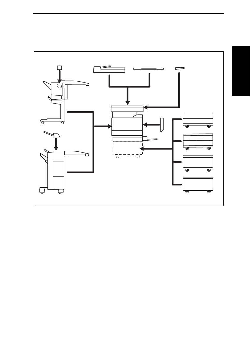
1. System configuration
1/2 System front view
[10]
[9]
[8]
[7]
[1] Machine [8] Job Separator JS-601
[2] Automatic Duplex Unit AD-501 [9] Finisher FS-601
[3] Paper Feed Cabinet PC-201 [10] Punch Kit PK-4 for FS-601
[4] Paper Feed Cabinet PC-101 [11] Reverse Automatic Document Feeder DF-601
[5] Desk DK-501 [12] Original Cover OC-501
[6] Paper Feed Cabinet PC-401 [13] Working Table WT-501
[7] Finisher FS-501
[11]
[1]
[12] [13]
[2]
[3]
[4]
[5]
[6]
4036fs1001j0
I Outline
1-1
Page 22

System configuration QC 2235plus Theory of Operation Ver.1.0 Feb. 2004
2/2 System rear view
[10]
[11]
[9]
I Outline
[8]
[7]
[1]
[5]
[6]
PC-101
PC-201
PC-401
[4]
[1] Machine [7] Local Interface Kit EK-501
[2] Vender Kit VK-501
(South Central America, North America,
Europe Only)
[3] Data Terminal DT-105
(South Central America, North America
Only)
[4] Dehumidifier Heater 1C [10] Hard Disk HD-501
[5] Video Interface Kit VI-501 [11] Expanded Memory Unit EM-301
[6] Image Controller X3e 22C-KM
[8] Mechanical Counter
[9] Key Counter Kit KIT-1
[2]
[3]
Dk-501
4036fs1002e0
1-2
Page 23

QC 2235plus Theory of Operation Ver.1.0 Mar. 2004 Product specifications
2. Product specifications
2.1 Type
Type Desktop-type printer integrated with scanner
Copying System Electrostatic dry-powdered image transfer to plain paper
Printing Process Tandem-type indirect electrostatic recording system
PC Drum Type OPC (organic photo conductor)
Scanning Density Equivalent to 600 dpi
Print Density Equivalent to 600 dpi in main scanning direction × 1800 dpi in sub scanning
Platen Stationary (mirror scan)
Original Scanning Scanning in main scanning direction with a CCD
Registration Rear left edge
Paper Feeding System
(Standard)
Three-way system
Exposure System Four-LED exposure
Developing System HMT developing system
Charging System DC comb electrode Scorotron system with electrode cleaning function
Image Transfer System Intermediate transfer belt system
Paper Separating System Selecting either application of nonwoven fabric bias + low-pressure paper
Fusing System Belt fusing
direction
(one-shot reading system)
Multiple Bypass: 150 sheets
Tray1: 250 sheets
Tray2: 500 sheets
(manual)
separator claws
I Outline
2.2 Functions
Types of Original Sheets, books, and three-dimensional objects
Max. Original Size A3 or 11 × 17
Multiple Copies 1 to 999
Warming-up Time 99 sec. or less (at ambient temperature of 23 °C and rated source voltage)
Image Loss
First Copy Time (Tray1, A4, full size)
Copying Speed for Multicopy Cycle
(A4, 8-1/2 × 11)
Fixed Zoom Ratios Full size ×1.000
Variable Zoom Ratios ×0.250 to ×4.000 in 0.001 increments
Exposure Lamp White rare-gas fluorescent lamp 30 W
Leading edge: 5 mm, Trailing edge: 3 mm,
Rear edge: 3 mm, Front edge: 3 mm
Monochrome print 6.8 sec. or less
Color print 12.8 sec. or less
Monochrome print 1-sided: 35 copies/min; 2-sided: 31 copies/min
Color print 1-sided: 22 copies/min; 2-sided: 22 copies/min
Reduction
Enlargement
Metric Area: ×0.500, ×0.707, ×0.816, ×0.866
Inch Area: ×0.500, ×0.647, ×0.733, ×0.785
Metric Area: ×1.154, ×1.224, ×1.414, ×2.000
Inch Area: ×1.214, ×1.294, ×1.547, ×2.000
1-3
Page 24

Product specifications QC 2235plus Theory of Operation Ver.1.0 Feb. 2004
2.3 Types of paper
I Outline
Copy paper type
Copy paper
dimensions
Paper Source Tray1 Tray2 Multiple Bypass
Plain paper (60 to 90 g/m
Translucent paper – – –
OHP transparencies
(crosswise feeding only)
Thick paper 1
(91 to 150 g/m
Thick paper 2
(151 to 209 g/m
Thick paper 3
(210 to 256 g/m
Postcards –
Envelopes –
Labels –
Max (width × length) 311 × 457 mm 297 × 432 mm 311 × 457 mm
Min (width × length) 90 × 140 mm 140 × 182 mm 90 × 140 mm
2
2
)
2
) *1
)
2
)
(20 sheets or
❍❍❍
❍
less)
*1: Image is not guaranteed when thick paper 3 is used.
Optional Paper Feed Cabinet: Only the plain paper weighing 60 to 90 g/m
Automatic Duplex Unit: Only the plain paper weighing 64 to 90 g/m
2.4 Maintenance
Machine Durability 800,000 prints or 5 years, whichever is earlier
–
–
–
–
2
is reliably fed.
2
is reliably fed.
❍
(20 sheets or
less)
❍
(10 sheets or
less)
❍
(20 sheets or
less)
2.5 Machine specifications
Power Requirements Voltage: AC100 V ±10 %
Frequency: 50/60 Hz ±0.3 Hz
Max Power Consumption 15 kW (100 V, 15 A)
Dimensions 903 (W) × 730 (D) × 770 (H) mm
Space Requirements 1014 (W) × 1151 (D) mm
Mass Approx. 100 kg (without IU)
2.6 Operating environment
Temperature 10 to 30 °C (with a fluctuation of 10 °C/h)
Humidity 15 to 85 % (with a fluctuation of 20 %/h)
1-4
Page 25

QC 2235plus Theory of Operation Ver.1.0 Mar. 2004 Product specifications
2.7 Built-in controllers
Printer Driver PCL5c printer driver
Scan Driver TWAIN driver
OS Compatibility Windows 98/Me, Windows NT/2000/XP, Windows Server 2003
Interface Ethernet 10/100BaseTX
NOTE
• These specifications are subject to change without notice.
I Outline
1-5
Page 26
Center cross section QC 2235plus Theory of Operation Ver.1.0 Feb. 2004
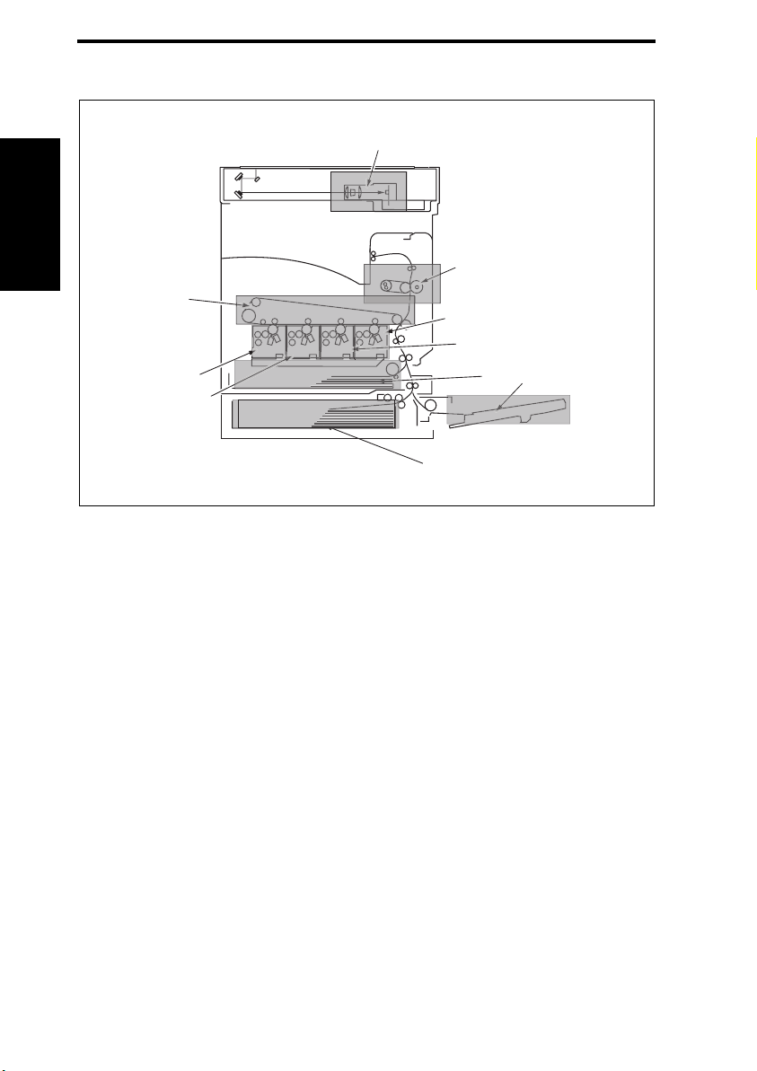
3. Center cross section
[1]
I Outline
[2]
[10]
[9]
[8]
[1] CCD Unit [6] Multiple Bypass
[2] Fusing Unit [7] Tray2
[3] Imaging Unit/Bk [8] Imaging Unit/M
[4] Imaging Unit/C [9] Imaging Unit/Y
[5] Tray1 [10] Transfer Belt Unit
[7]
[3]
[4]
[5]
4036ma101c0
[6]
1-6
Page 27
QC 2235plus Theory of Operation Ver.1.0 Mar. 2004 Paper path
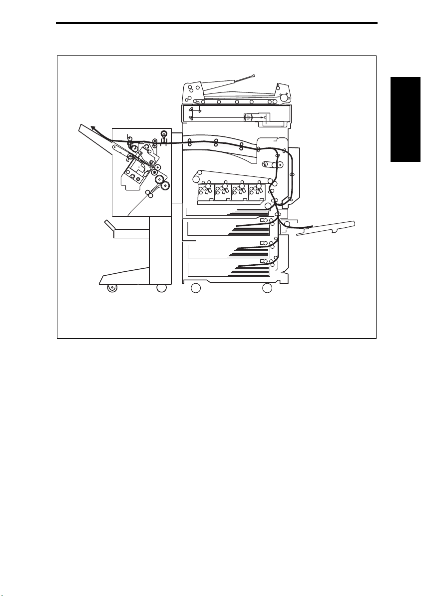
4. Paper path
I Outline
1-7
4036ma102c0
Page 28
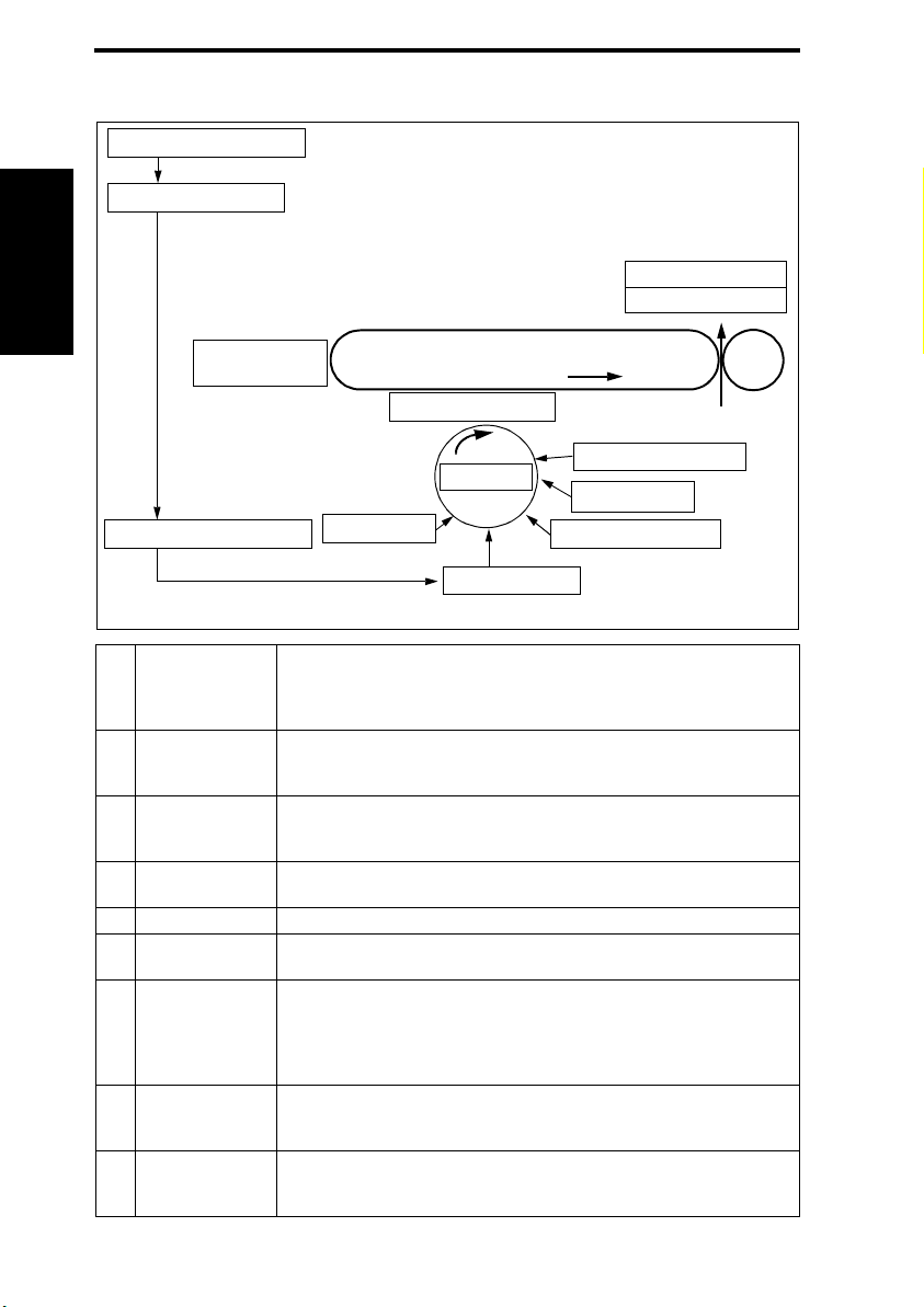
Image creation process QC 2235plus Theory of Operation Ver.1.0 Feb. 2004
5. Image creation process
[1] Photoelectric Conversion
[2] IR Image Processing
I Outline
[11] Transfer
Belt Cleaning
[8] 1st Image Transfer
[4] PC Drum
[3] Printer Image Processing
Photoelectric
[1]
Conversion
IR Image
[2]
Processing
Printer Image
[3]
Processing
[4] PC Drum
[5] PC Drum Charging • A negative DC charge layer is formed on the surface of the PC Drum.
[6] LED Exposure
[7] Developing
[8] 1st Image Transfer
[9] 2nd Image Transfer
[7] Developing
[6] LED Exposure
• The light reflected off the surface of the original is separated into different
colors using the color filters (R, G, and B); CCD then converts it into a corresponding electric signal and outputs the signal to the IR Imaging Processing Section.
• The electric signal is converted to 8-bit digital image signals. After going
through some corrections, video signals (C, M, Y, and Bk) are output to
the Printer Image Processing Section.
• The video signals (C, M, Y, and Bk) go through some corrections. Following digital-to-analog conversion, these signals are used for the control of
the intensity level of the LED.
• The image of the original projected onto the surface of the PC Drum is
changed to a corresponding electrostatic latent image.
• The surface of the PC Drum is irradiated with LED light and an electrostatic latent image is thereby formed.
• The toner, agitated and negatively charged in the Developer Mixing Chamber, is attracted onto the electrostatic latent image formed on the surface of
the PC Drum. It is thereby changed to a visible, developed image.
• AC and DC negative bias voltages are applied to the Developing Roller,
thereby preventing toner from sticking to the background image portion.
• A DC positive voltage is applied to the backside of the Transfer Belt,
thereby allowing the visible, developed image on the surface of each of
the PC Drums (Y, M, C, and Bk) to be transferred onto the Transfer Belt.
• A DC positive voltage is applied to the backside of the paper, thereby
allowing the visible, developed image on the surface of the Transfer Belt to
be transferred onto the paper.
[5] PC Drum Charging
[10] Paper Separation
[9] 2nd Image Transfer
[12] PC Drum Cleaning
[13] Main Erase
1-8
Page 29

QC 2235plus Theory of Operation Ver.1.0 Mar. 2004 Image creation process
[10] Paper Separation
Transfer Belt
[11]
Cleaning
[12] PC Drum Cleaning • The residual toner left on the surface of the PC Drum is scraped off.
[13] Main Erase
• The paper, which has undergone the 2nd image transfer process, is neutralized so that it can be properly separated from the Transfer Belt by the
Paper Separator Claws.
• A charge is applied to the Transfer Belt. By potential difference, residual
toner on the surface of the Transfer Belt is collected for cleaning.
• The surface of the PC Drum is irradiated with light, which neutralizes any
surface potential remaining on the surface of the PC Drum.
I Outline
1-9
Page 30

Page 31

QC 2235plus Theory of Operation Ver.1.0 Mar. 2004 Overall composition
II Composition/Operation
2. Overall composition
2.1 Timing chart at machine power up
Power Switch ON
Fusing Pressure Roller Heater
Lamp (H3)
Heating Roller Heater Lamp/1
(H1)
Fusing Pressure Roller Pressure/
Retraction Motor (M19)
Fusing Drive Motor (M2)
Exposure Lamp (FL201)
Scanner Motor (M201)
Main Motor (M1)
1st Image Transfer Pressure/
Retraction Motor (M11)
1st Image Transfer Retraction
Position Sensor (PC12)
Transfer Belt Cleaning Bias
Cleaning Brush Motor (M22)
2nd Image Transfer Pressure/
Retraction Motor (M13)
2nd Image Transfer Pressure/
Retraction Position Sensor (PC29)
2nd Image Transfer Bias
Retraction
Bk Pressure
Retraction
Pressure/Retraction
Pressure
Retraction
100°C
Temperature Control
Pressure
Retraction
II Composition/Operationn
2-1
4036ma2052e0
Page 32

Overall composition QC 2235plus Theory of Operation Ver.1.0 Feb. 2004
2.2 Control block diagram
Scanner Section
CCD Sensor
Board (PWB-A)
Inverter Board
Exposure Lamp
(FL201)
Scanner Motor Drive
Board (PWB-IC)
II Composition/Operationn
Image Processing Board (PWB-C)
MFP Control Board (PWB-MFP)
Standard
Controller
LPH/Y
IC-401
Image
Processing
LED Drive Board
(PWB-LED)
LPH/M
LPH/C
Scanner Motor (M201)
Control Board (PWB-MC)
LPH/Bk
Finishing
Option
CPU
Panel
Paper
Source
Option
DF-601
Printer Section
Paper Takeup/Transport
Process
Fusing
AD-501
Control System Line
Image Bus Line
4036ma2053e0
2-2
Page 33

QC 2235plus Theory of Operation Ver.1.0 Mar. 2004 Scanner section (IR section)
3. Scanner section (IR section)
3.1 Composition
[1]
[2]
4036ma2110c0
[3]
[13]
[4]
[5]
[12]
[11]
[6]
4036ma2501c0
II Composition/Operationn
[7]
[8]
[9]
[10]
4036ma2001c1
2-3
Page 34

Scanner section (IR section) QC 2235plus Theory of Operation Ver.1.0 Feb. 2004
Key Name Function/System
[1] Original Cover Angle Sensor (PC202) • Validates or resets the size of the original.
[2] Original Size Sensor FD1 (PC203) • Detects the original of a small size in the FD direction.
[3] Scanner Motor Drive Board (PWB-IC) • Drives the Scanner Motor.
[4] Original Size Sensor FD2 (PC204) • Detects the original of a large size in the FD direction.
• Drives the Scanner Drive Cables for moving the Expo-
[5] Scanner Motor (M201)
sure Lamp and Scanner.
• Drives the Scanner Motor Drive Board (PWB-IC).
•
Three-phase stepping motor
[6] Lens • F5.0, focal length 71.2 mm
• Changes optical image data to a corresponding electric
[7] CCD Unit *1
signal (600 dpi).
• Three-line (RGB) linear image sensor
• Detects the position of the Original Cover or ADF,
[8] Size Reset Switch (SW201)
whether it is raised or lowered.
• Resets the size of the original when the ADF is raised.
• Magnetic sensor type
[9] Image Processing Board (PWB-C) • Processes image data that has been scanned.
[10] Exposure Unit • Slit exposure
[11] Mirror Unit • Reflects the light reflected off the original.
II Composition/Operationn
[12] Original Size Sensor CD1 (PC206) • Detects the original of a large size in the CD direction.
[13] Scanner Home Sensor (PC201) • Detects the Scanner at its home position.
∗1: CCD Unit
R
G
B
Sub Scanning
Direction
Main Scanning
Direction
Scanning Direction
2-4
CCD Sensor
37.3 µm
37.3 µm
9.325 µm
9.325 µm
4036ma2602c0
Page 35

QC 2235plus Theory of Operation Ver.1.0 Mar. 2004 Scanner section (IR section)
3.2 Drive
[4]
[3]
[2]
[5]
[1]
[6]
[1] Scanner Drive Cable/R [4] Scanner Motor
[2] Mirror Unit [5] Scanner Drive Cable/F
[3] Exposure Unit [6] Scanner Home Sensor
4036ma2002c1
3.3 Operation
3.3.1 Scan and Exposure Lamp control A. When the Power Switch is turned ON
1. The Exposure Unit moves in the return direction until the Scanner Home Sensor is activated. It does not move if the Scanner Home Sensor is already activated.
2. The Exposure Unit moves in the scan direction and stops at a position under the shading correction sheet.
3. The gain value of the CCD Sensor output voltage is adjusted for R, G, and B.
4. A shading correction is made.
5. After the adjustment has been made, the Exposure Unit moves in the return direction
and stops at the Scanner Home Sensor. This position serves as the home position.
* The same operation is performed for the auto and manual exposure control.
Home Position
Gain Adjustment and Shading Correction
II Composition/Operationn
2-5
Exposure Lamp (FL201) ON
Scanner Movement
4036ma2190c0
Page 36

Scanner section (IR section) QC 2235plus Theory of Operation Ver.1.0 Feb. 2004
B. When the Start key is pressed
1. The Exposure Lamp turns ON when the Start key is pressed.
2. The gain adjustment is made when the Exposure Unit moves past the point under the
shading sheet. Thereafter, a shading correction is made.
3. The Exposure Unit starts a scan motion with the original position.
4. After completing the scan motion for the original, the Exposure Unit temporarily stops
and the Exposure Lamp goes out.
5. The Exposure Unit makes a return motion and stops at the home position. Each of the
R, G, and B data is stored in memory during a single scan motion. The Exposure Unit
therefore makes only a single scan motion even for a multi-copy cycle.
Home Position
Original Position
Exposure Lamp (FL201) ON
Gain Adjustment and Shading Correction
Scan
II Composition/Operationn
3.3.2 Original Size Detection control
A. Detection Method
• Reflective size sensors are used for detection of the size of the original.
• Mounting the optional size sensors permits detection of originals of inch size.
Original Size Sensor FD1
(PC203)
Metric area: Standard
Inch area: Option
A5R
B5R
A4R
B4,
B5
A3,
A4
Original Size Sensor
CD1 (PC206)
Original Size Sensor
FD2 (PC204)
7
6
8
Original Size Sensor
CD2 (PC207): Option
1
B5
8.5 X 11
A4,
A5R
234
Original Size Sensor
FD3 (PC205): Option
8.5 X 11 R 8.5 X 14 11 X 17
5
A4R
B5R
B4
4036ma2191c0
8.5 X 14
8.5 X 11 R
11 X 17
8.5 X 11
A3
4036ma2003c0
2-6
Page 37

QC 2235plus Theory of Operation Ver.1.0 Mar. 2004 Scanner section (IR section)
• The Image Processing Board determines the size of the original based on the combination of detection made by each of the Original Size Sensors, whether or not there is an
original loaded.
• An original of an irregular size is rounded to the nearest standard size.
Metric Area
Original Size
Determined
A3 ●●●●●
B4 ●●●●–
A4R ●●● ––
A4 ● ––●●
B5 – – – ● –
A5R ● ––––
8.5 × 11R ●● –––
: Original Loaded –: Original Not Loaded
●
FD1 FD2 CD1
12367
• When the optional sensors are mounted
Original Size
Determined
A3 ●●●●●●●●
B4 ●●●●●● ––
A4R ●●●●––––
A4 ● ––––●●●
B5R ●●––––––
B5 –––––● ––
A5R ● –––––––
11 × 17 ●●●●●●● –
8.5 × 14 ●●●●● –––
8.5 × 11R ●●● –––––
8.5 × 11 ● ––––●● –
: Original Loaded –: Original Not Loaded
●
FD1 FD2
12345678
FD3
(option)
CD1
CD2
(option)
II Composition/Operationn
2-7
Page 38

Scanner section (IR section) QC 2235plus Theory of Operation Ver.1.0 Feb. 2004
Inch Area - Standard
Original Size
Determined
11 × 17 ●●●●
B4 ●●● –
8.5 × 14 ●● ––
8.5 × 11R ● –––
8.5 × 11 – – ●●
B5 – – ● –
: Original Loaded –: Original Not Loaded
●
FD2 CD1
2367
• When the optional sensors are mounted
Original Size
Determined
11 × 17 ●●●●●●● –
8.5 × 14 ●●●●●–––
FLS ●●●●––––
II Composition/Operationn
8.5 × 11R ●● –––––
8.5 × 11 ● ––––●● –
5.5 × 8.5R ● –––––––
A3 ●●●●●●●●
B4 ●●●●●●––
A4R ●●● ––––
A4 ● ––––●●●
B5 –––––● ––
: Original Loaded –: Original Not Loaded
●
FD1
(option)
12345678
FD2
FD3
(option)
CD1
CD2
(option)
B. Detection Timing (When the ADF is Used)
Original Size Sensors FD1 (PC203),
FD2 (PC204), and FD3 (PC205)
Original Size Sensors CD1 (PC206)
and CD2 (PC207)
Original Cover Angle Sensor (PC202)
Size Reset Switch (SW201)
Validates the original size
when the ADF is lowered
Resets the original size
when the ADF is raised
4036ma2007c0
• The original size is validated if the Start key is pressed with the ADF in the raised position.
2-8
Page 39

QC 2235plus Theory of Operation Ver.1.0 Mar. 2004 Write section (PH section)
4. Write section (PH section)
4.1 Composition
[1]
4036ma2218c0
4036ma2502c0
[2]
[5]
[3]
[4]
4036ma2219c0
Key Name Function/System
[1] LED Unit • Four LED assemblies are integrated into a single unit.
[2] SELFOC Lens
[3] LED Chips
• The rays of light emitted by the LED chips are brought to a focus
on the surface of the PC Drum to form a full-size image.
• Approximately 7,700 LED chips (600 dpi) arranged in the main
scanning direction
[4] LED Assy/Y, M, C, Bk • LED Assy for each color of Y, M, C, and Bk
[5] PC Drum/Y, M, C, Bk • Irradiated with LED light to form an electrostatic latent image.
II Composition/Operationn
2-9
Page 40

Write section (PH section) QC 2235plus Theory of Operation Ver.1.0 Feb. 2004
4.2 Operation
4.2.1 Outline
• Each of the PC Drums is irradiated with LED light and an electrostatic latent image is
thereby formed.
• The LED print head is a fixed scanning type exposure system that includes approx.
7,700 LED chips (600 dpi) arranged in the main scanning direction and a SELFOC lens
array, or SLA that brings rays of light emitted by the LED chips to a focus on the surface
of the PC Drum to form a full-size image.
• The special service jig for cleaning the surface of the LED print head should be used,
since a special coating is applied to the surface of the SLA to prevent ozone from sticking
to it.
II Composition/Operationn
PC Drum Y
Tran sfer Bel t
Y Bk
LED/Y LED/M
M
SELFOC Lens
2nd Image Transfer Roller
C
LED/C LED/Bk
4036ma2004c1
Approx. 7,700
LED chips
4036ma2222c0
2-10
Page 41

QC 2235plus Theory of Operation Ver.1.0 Mar. 2004 Write section (PH section)
4.2.2 Color Shift Correction System
• In a tandem engine, in which an independent image reproduction process is provided for
each of the four different colors of toner. Incorrect color registration, or color shift, is
therefore more likely to occur due to each of the LED assemblies being out of correct
position. The color shift correction system automatically detects any misalignment
among the different colors, correcting it both in the main scanning and sub scanning
directions.
• The color shift detection sequence proceeds as follows. A detection pattern each in the
sub scanning direction is produced at the front and rear on the Transfer Belt. Each of
AIDC/Registration Sensor/1 and /2 at the front and rear reads the corresponding pattern.
The amount of color shift in the sub scanning direction is then calculated and stored in
memory. A detection pattern each in the main scanning direction is next produced at the
front and rear on the Transfer Belt. Each of AIDC/Registration Sensor/1 and /2 at the
front and rear reads the corresponding pattern. The amount of color shift in the main
scanning direction is then calculated and stored in memory. Based on the data representing the amounts of color shift, the machine calculates how much each of the different
colors should be corrected. The correction data is further stored in memory. Based on
the data stored in memory, the machine controls each dot during production of image
outputs, thereby correcting the color shift (varying the timing at which the LED is turned
ON).
• The color shift correction is made when the Left Door is opened and closed, the IU is
removed and reinstalled, or an image stabilization sequence is carried out from the control panel.
II Composition/Operationn
Detection Pattern for Sub
Scanning Direction
Transfer Belt
Detection Pattern for Main
Scanning Direction
AIDC/Registration Sensor/1
and /2 (PC8 and PC9)
2-11
4036ma2226c0
4036ma2227c0
Page 42

Imaging Unit section (IU section) QC 2235plus Theory of Operation Ver.1.0 Feb. 2004
5. Imaging Unit section (IU section)
5.1 Composition
[1]
4036ma2130c0
[6]
II Composition/Operationn
4036ma2239c0
Key Name Function/System
[1] PC Drum/Y, M, C, Bk
[2] Cleaning Blade • Scrapes toner off the surface of the PC Drum.
[3] Toner Collecting Screw
[4] PC Drum Charge Corona/Y, M, C, Bk
Main Erase Lamp/Y, M, C, Bk
[5]
(LA1 to LA4)
[6] Developing Unit/Y, M, C, Bk
• Forms an image of each of different colors.
•OPC drum (φ30 mm)
• Conveys waste toner from the IU to the Toner Collecting Section.
• Screw type
• Deposits a charge across the entire surface of the
PC Drum.
• DC comb electrode Scorotron system
• Neutralizes any charge left on the surface of the PC
Drum.
•LED type
• Developer capacity 400 g (C, M, Y, Bk)
• T/C ratio 8% (C, M, Y, Bk)
4036ma2503c0
[1]
[2]
[3]
[4]
[5]
2-12
Page 43

QC 2235plus Theory of Operation Ver.1.0 Mar. 2004 Imaging Unit section (IU section)
5.2 Drive
[2]
[1]
[4]
[3]
4036ma2008c1
II Composition/Operationn
4036ma2007c1
[1] Developing Clutch/Bk (CL2) [3] Color Developing Motor (M6)
[2] Bk PC Motor (M7) [4] Color PC Drum Motor (M5)
2-13
Page 44

Imaging Unit section (IU section) QC 2235plus Theory of Operation Ver.1.0 Feb. 2004
5.3 Operation
5.3.1 IU Life control
• Each IU has EEPROM that detects a new IU and keeps track of the service life of the IU.
A. New IU detection
• new IU is detected when 24 V is turned ON as the Power Switch is turned OFF and ON
or the Front Door is opened and closed. If a new IU is not detected the machine does not
execute image stabilization sequence.
• When a new IU is detected, an ATDC adjustment sequence is carried out.
Operation when a new IU is detected
Transfer Belt
is retracted
ATDC
automatic
adjustment
Transfer Belt
cleaning
1st image
transfer/ATVC
adjustment
Image stabilization
Operation when a new IU is not detected
II Composition/Operationn
Transfer Belt
is retracted
Transfer Belt
cleaning
1st image
transfer/ATVC
adjustment
Image stabilization
B. When life is reached
• The IU Life Counter is used to keep track of IU life.
• When the life value is reached, a warning message is given on the screen. When a predetermined number of printed pages are produced after the life value has been reached,
the machine inhibits the initiation of a new print cycle with a message prompting the user
to replace the IU given on the screen.
At print stop When a life value is reached
4036ma2058e0
4036ma2133c0
4036ma2059e0
• The warning screen and IU replacement screen change when the settings are changed
for “Display PM Parts Lifetime” and “Unit Change” available from the Tech. Rep. mode
and “IU Life Stop Setting” available from the Security mode.
2-14
Page 45

QC 2235plus Theory of Operation Ver.1.0 Mar. 2004 Photo Conductor section
6. Photo Conductor section
6.1 Composition
Charge Generating
Charge Transport
Layer (CTL)
Layer (CGL)
Aluminum
Cylinder
4036ma2338c0
[1]
Key Name Function/System
[1] PC Drum/Y, M, C, Bk
4036ma2543c0
• Forms an image of each of different colors.
•OPC drum (φ30 mm)
6.2 Drive
[2]
[1]
[6]
[1] Color PC Drum Motor (M5) [4] PC Drum/C
[2] Bk PC Motor (M7) [5] PC Drum/M
[3] PC Drum/Bk [6] PC Drum/Y
[3]
[5]
[4]
4036ma2551c0
II Composition/Operationn
2-15
Page 46

Photo Conductor section QC 2235plus Theory of Operation Ver.1.0 Feb. 2004
6.3 Operation
6.3.1 PC Drum Drive mechanism
• Two independent PC Drum motors are used for the drive mechanism to suppress incorrect color registration and uneven pitch.
• The Color PC Drum Motor drives the PC Drums/Y, M, and C, while the Bk PC Motor
drives the PC Drum/Bk.
• Gears having a large diameter are used to enhance rotating accuracy of the PC Drums.
• The use of gears having a large diameter provides a large number of gear teeth, which
suppresses uneven pitch and eccentricity.
• Drive is transmitted to each of the PC Drums when the triangular coupling is engaged
with the mating part that also has a triangular shape.
Color PC Drum Motor (M5)
Bk PC Motor (M7)
Large-diameter Gear
Shaft
II Composition/Operationn
Coupling
4036ma2051c0
Coupling
4036ma2552c0
4036ma2544c0
6.3.2 PC Drum Phase control
• To enhance image quality, sensors are used to detect operating conditions while the PC
Drum turns, thereby providing drum drive control.
2-16
Page 47

QC 2235plus Theory of Operation Ver.1.0 Mar. 2004 Photo Conductor section
6.3.3 PC Drum small amount rotation control
• Humidity around the IU can produce a difference in sensitivity among different PC
Drums. This could lead to drum memory, allowing black bands to occur in the image. In
addition, ozone stagnant in areas near the PC Drum Charge Corona reduces sensitivity
of the PC Drums, causing white bands to occur in the image.
• To prevent these image problems, it should be ensured that the same face of the PC
Drum is left exposed to the same condition for an extended period of time. The PC Drum
is therefore turned at regular intervals to keep the surface sensitivity uniform.
A. PC Drum small amount rotation timing
• The PC Drum is turned the small amount when a predetermined threshold value of the
cumulative PC Drum driven distance is exceeded during a multi-print cycle or when intermittent print cycles are consecutively run with an intermission of less than a predetermined period of time between them.
PC Drum
4036ma2549c0
II Composition/Operationn
2-17
Page 48

Charge Corona section QC 2235plus Theory of Operation Ver.1.0 Feb. 2004
7. Charge Corona section
[1]
[3]
4036ma2130c0
4036ma2506c0
[4]
[3]
[1]
II Composition/Operationn
[5]
4036ma2138c0
Key Name Function/System
[1] Corona Wire • Comb electrode type
[2] Corona Wire Cleaning Lever
• For cleaning the corona wire
• Slide out to clean the corona wire.
[3] Grid Mesh • Applies the grid voltage
[4] Cleaning Blade • Scrapes residual toner off the surface of the PC Drum
• Illuminates the surface of the PC Drum to neutralize
[5] Main Erase Lamp
any surface potential remaining on the surface of the
PC Drum
•LED type
[2]
4036ma2009c1
2-18
Page 49

QC 2235plus Theory of Operation Ver.1.0 Mar. 2004 Charge Corona section
7.1 Operation
7.1.1 PC Drum Charge Corona ON/OFF control
• The grid voltage (VG) applied to the Grid Mesh is controlled through the image stabilization control.
Color PC Drum Motor Energized
Bk PC Motor Energized
Drum Charge Corona Bias Y, M, C
Drum Charge Corona Bias Bk
Color Developing Motor (M6)
Developing Clutch/Bk (CL2)
4036ma2251c0
7.1.2 Cleaning/Main Erase mechanism
A. Cleaning/main erase operation
1. The Cleaning Blade is pressed up against the surface of the PC Drum, scraping resid-
ual toner off the surface (forward blade system).
2. Toner, which has been scraped off the surface of the PC Drum, is fed by the Toner Col-
lecting Screw back toward to the Conveying Screw in the rear of the machine. It is then
collected in the Waste Toner Collecting Box.
3. The surface of the PC Drum after the image transfer process is irradiated with light from
the Main Erase Lamp. This neutralizes any potential left on the surface of the PC Drum.
II Composition/Operationn
4036ma2539c0
Toner Collecting
Screw
Cleaning
Blade
Main Erase
Lamp
2-19
Cleaning Blade
4036ma2505c0
Page 50

Developing section QC 2235plus Theory of Operation Ver.1.0 Feb. 2004
8. Developing section
8.1 Composition
[3]
[2]
[7]
4036ma2130c0
[4]
[9]
[5]
II Composition/Operationn
[8]
[6]
[2]
4036ma2010c1
Key Name Function/System
[1] Doctor Blade • Controls the height of the developer brush on the Developing Roller
Supply/Agitating/Convey-
[2]
ing Screws
[3] Developing Roller
• Vertical two-shaft circulating system that employs screws having a
small diameter arranged in the vertical direction
• Conveys developer through magnetism to the point of development
• Two-component developing system
• Drives the PC Drum of the IU/Bk
[4] Bk PC Motor (M7)
• Energized by the Control Board (PWB-MC)
• Brushless DC motor
[5] PC Drum/Bk
Developing Clutch/Bk
[6]
(CL2)
Color PC Drum Motor
[7]
(M5)
[8] PC Drum/Y
• Forms an image
•OPC drum (φ30 mm)
• Transmits drive to the Developing Roller, Supply/Agitating/Conveying Screws, and Toner Collecting Screw of the IU/Bk.
• Drives the PC Drums of the IU/Y, IU/M, and IU/C
• Energized by the Control Board (PWB-MC)
• Brushless DC motor
• Forms an image of each of different colors
•OPC drum (φ30 mm)
• Drives the Developing Rollers, Supply/Agitating/Conveying Screws,
Color Developing Motor
[9]
(M6)
and Toner Collecting Screws of the IU/Y, IU/M, and IU/C
• Energized by the Control Board (PWB-MC)
• Brushless DC motor
[1]
4036ma2139c0
[3]
4036ma2011c1
2-20
Page 51

QC 2235plus Theory of Operation Ver.1.0 Mar. 2004 Developing section
8.2 Drive
[9]
[6]
[8]
[7]
[5]
[1]
[2]
[4]
4036ma2603c0
[1] PC Drum/Bk [6] Bk PC Motor (M7)
[2] Developing Roller [7] PC Drum/Y
[3] Toner Collecting Screw [8] Color Developing Motor (M6)
[4] Supply/Agitating/Conveying Screws [9] Color PC Drum Motor (M5)
[5] Developing Clutch/Bk (CL2)
[3]
4036ma2604c0
II Composition/Operationn
2-21
Page 52

Developing section QC 2235plus Theory of Operation Ver.1.0 Feb. 2004
Retraction Signal
8.3 Operation
8.3.1 Developing Drive control
Main Motor ON Signal
DCDCPrinting DC
DC
Printing DC
II Composition/Operationn
Developing Bias/Y, M, C
Main Motor (M1)
Color PC Drum Motor (M5)
Bk PC Motor (M7)
Developing Bias/Bk
Drum Charge Corona Bias Y, M, C
Drum Charge Corona Bias Bk
Color Developing Motor (M6)
Developing Clutch/Bk (CL2)
1st Image Transfer Pressure/
Retraction Motor (M11)
2nd Image Transfer Pressure/
Retraction Motor (M13)
*1: Actual YMC timing depends on the position of each PC Drum.
8.3.2 Developer flow
1. Toner supplied from the front end of the Developing Unit is fed to the lower screw. It is
then fed to the rear of the unit, while being mixed with developer and electrically
charged by the Supply/Agitating/Conveying Screws.
2. The ATDC Sensor installed on the underside of the Developing Unit detects toner-tocarrier ratio during this time.
3. The developer, fed to the rear of the Developing Unit, is conveyed further to the upper
screw.
4. Because of the magnetic pole positioning of the Developing Roller, the developer is
conveyed onto the upper part of the Developing Roller. The Doctor Blade then controls
the height of the developer brush to ensure that the developer on the Developing Roller
levels out.
5. The Toner sticks to the electrostatic latent image on the surface of the PC Drum. The
developer that is left on the Sleeve is returned to the upper screw by the magnetic pole
positioning of the Developing Roller. It is then conveyed to the front side of the Developing Unit.
For IU/Y
PC Drum/Y
AC *1
AC *1
Developing Roller
Doctor Blade
DC
4036ma2152c0
Toner Supplied
from Hopper
Supply/Agitating/Conveying Screws
2-22
4036ma2605c0
Page 53

QC 2235plus Theory of Operation Ver.1.0 Mar. 2004 Developing section
8.3.3 Developing bias
• The developing bias voltage (Vb) is applied to the Developing Roller so that an adequate
amount of toner is attracted onto the surface of the PC Drum.
• In addition to the negative DC component, AC voltage is applied during development to
help toner to be attracted more easily to the surface of the PC Drum. This AC component
is applied only while development is taking place.
• The developing bias (Vb) is supplied from High Voltage Unit/2.
Developing Roller
Developing Bias
4036ma2507c0
8.3.4 HMT (High grade Micro Toning) development
• The machine employs the two-component non-contact development system.
• With the HMT method, the magnetic developer brush does not rub against the surface of
the PC Drum (the images). Accordingly, sharper line images can be reproduced, involving no uneven image density at the trailing edge or thin lines and achieving even finer
reproduction of the solid image areas.
II Composition/Operationn
Developing Roller
PC Drum
4036ma2013c1
8.3.5 Developer scattering prevention mechanism
• To prevent the image and machine interior from being dirtied, a filter installed in the rear
of the IU and the Toner Suction Fan Motor work to trap toner particles rising up during
development.
IU
Holder
Filter
Holder
4036ma2247c0
2-23
Page 54

Developing section QC 2235plus Theory of Operation Ver.1.0 Feb. 2004
8.3.6 ATDC Sensor control
• The ATDC Sensor is mounted on the underside of each of the Developing Sections. The
sensor for C, M, and Y is an optical type, while that for Bk is a magnetic type. Each of
these sensors detects toner-to-carrier ratio (T/C) of the developer. The reading is used
for determining the amount of toner supplied.
• Only when a new Imaging Unit is installed in the machine, an automatic adjustment is
made of each of these ATDC Sensors. The sensors cannot be adjusted manually.
• The target T/C is 8 % both for color and Bk. This T/C can, however, be changed using
“ATDC Level” of “Image Adjust” available from the Tech. Rep. mode.
A. Optical ATDC sensor
• A bias is applied to the ATDC Sensor window to prevent toner from sticking to it. There is
a magnetic brush provided for the Conveying Screw portion to clean the surface of the
window.
• The sensor portion is separated from the Developing Section (Imaging Unit). When the
ATDC Sensor is replaced, it is necessary to replace the Imaging Unit with a new one.
• This represents the fact that the ATDC Sensor is adjusted only when a new Imaging Unit
is installed. In addition, if the LPH Unit is to be replaced, it is necessary to remove the
ATDC Sensor from the old LPH Unit and mounted it in the new LPH Unit.
B. Magnetic ATDC Sensor
• The magnetic permeability (powder density) of the carrier in the developer is measured
II Composition/Operationn
to determine the T/C.
• A mylar is provided for the Conveying Screw portion to scrape toner off the surface of the
ATDC Sensor.
• The ATDC Sensor is integrated with the Imaging Unit. When the ATDC Sensor is to be
replaced with a new one, the entire Imaging Unit must be replaced.
Magnetic
Brush
ATDC
Sensor
Window
ATDC Sensor/Y, M, C ATDC Sensor/Bk
Optical ATDC Sensor
ATDC Sensor/C, M, Y
(PWB-N1, N2, N3)
4036ma2187c0
4036ma2508c0
Magnetic ATDC Sensor
Mylar
2-24
4036ma2504c0
ATDC Sensor/Bk
4036ma2188c0
Page 55

QC 2235plus Theory of Operation Ver.1.0 Mar. 2004 Developing section
C. ATDC window bias
• Since the optical ATDC Sensor is used for C, M, and Y, a bias is applied to the ATDC window to prevent toner from sticking to it. No bias is applied to the ATDC Sensor for Bk,
which is the magnetic type.
• The bias is applied from the bias terminal of the LED Unit by way of the mounting screw
of the ATDC window to the ATDC window.
ATDC Bias
ScrewATDC Window
4036ma2509c0
II Composition/Operationn
2-25
Page 56

Toner Supply section QC 2235plus Theory of Operation Ver.1.0 Feb. 2004
9. Toner Supply section
9.1 Composition
[1] [4][2] [3]
4036ma2143c0
II Composition/Operationn
[13]
[11]
[12]
[6][5]
[7] [8]
4036ma2510c0
[9]
[10]
[14]
4036ma2512c1
4036ma2511c0
Key Name Function/System
[1] Cartridge/Y • Replenishes the supply of Y toner
[2] Cartridge/M • Replenishes the supply of M toner
[3] Cartridge/C • Replenishes the supply of C toner
[4] Cartridge/Bk • Replenishes the supply of Bk toner
[5] Toner Set Sensor/Bk • Detects Cartridge/Bk as it is loaded in position
[6] Toner Set Sensor/C • Detects Cartridge/C as it is loaded in position
2-26
Page 57

QC 2235plus Theory of Operation Ver.1.0 Mar. 2004 Toner Supply section
Key Name Function/System
[7] Toner Set Sensor/M • Detects Cartridge/M as it is loaded in position
[8] Toner Set Sensor/Y • Detects Cartridge/Y as it is loaded in position
• Drives the Agitating Blades and Metering Rollers of
[9] Toner Supply Motor Y/M (M4)
Cartridges/Y and M
• Energized by the Control Board (PWB-MC)
• Two-phase stepping motor
• Drives the Agitating Blades and Metering Rollers of
[10] Toner Supply Motor C/Bk (M3)
Cartridges/C and Bk
• Energized by the Control Board (PWB-MC)
• Two-phase stepping motor
[11] Agitating Blade/Y, M, C, Bk • Agitates each of different colors of toner
Toner Near-Empty Sensor PQ/Y, M, C,
[12]
Bk (PC15, PC16, PC17, PC18)
Toner Near-Empty Sensor LED/Y, M, C,
[13]
Bk (PC21, PC22, PC23, PC24)
[14] Metering Roller/Y, M, C, Bk
• Detects a near-empty condition of toner in Toner
Cartridge/Y, M, C, Bk
• Detects a near-empty condition of toner in Toner
Cartridge/Y, M, C, Bk
• Limits the amount of each of different colors of
toner supplied
9.2 Drive
[1]
[2]
[3]
II Composition/Operationn
4036ma2514c0
[4]
[1] Toner Supply Motor Y/M (M4) [3] Agitating Blade/Y, M, C, Bk
[2] Toner Supply Motor C/Bk (M3) [4] Metering Roller/Y, M, C, Bk
2-27
4036ma2515c1
Page 58

Toner Supply section QC 2235plus Theory of Operation Ver.1.0 Feb. 2004
9.3 Operation
9.3.1 Toner Replenishing mechanism/control A. Toner replenishing mechanism
• Toner is supplied from the Toner Cartridge of each color to the Imaging Unit of each color
according to the T/C detected by the corresponding ATDC Sensor.
• A single Toner Supply Motor is turned either forward or backward to supply toner of two
different colors (Toner Supply Motor for Bk and C, and Toner Supply Motor for Y and M).
Toner Supply
Motor C/Bk (M3)
Turned forward Energized Deenergized Turned forward Energized Deenergized
Turned backward Deenergized Energized Turned backward Deenergized Energized
When Bk Toner is Supplied When C Toner is Supplied
Bk Ton er C To n er
Toner Supply
Motor Y/M (M4)
Y Toner M Toner
II Composition/Operationn
One-way clutch turns.
4036ma2018c1
One-way clutch turns.
• Replenishing operation
1. Drive of the Toner Supply Motor is transmitted through a gear train to the drive gears of
the Toner Cartridges of two colors. A one-way clutch is used for each of these drive
gears, meaning that the drive gear turns in one direction only. Either one of these two
drive gears is turned according to whether the Toner Supply Motor turns forward or
backward.
2. As the drive gear turns, the Metering Roller turns to replenish the supply of a predeter-
mined amount of toner for the Imaging Unit. Rotation of the drive gear also turns the
Agitating Blade of the Toner Cartridge to agitate toner in the Toner Cartridge.
B. Toner replenishing control
• T/C is detected when the Developing Clutch/Bk (CL2) is energized for Bk or when the
Color Developing Motor (M6) is energized for C, M, and Y (during a copy cycle).
• The actual reading of T/C taken is compared with the T/C setting made in “ATDC Level”
of “Image Adjust” available from the Tech. Rep. mode. Based on this comparison, the
toner replenishing time is determined.
• Since toner replenishing is possible only while the developer is being agitated, the maximum toner replenishing time is fixed. If it is not possible to replenish the supply of the
required amount of toner within this maximum replenishing time, the remainder time is
stored in memory and added to the replenishing time for the next replenishing sequence.
4036ma2025c1
2-28
Page 59

QC 2235plus Theory of Operation Ver.1.0 Mar. 2004 Toner Supply section
9.3.2 Toner Near-Empty and Toner Empty detection control
• A toner near-empty/empty condition is detected by the Toner Near-Empty Sensor PQ
and LED mounted on each of the Toner Cartridges.
• A toner empty condition is detected by the ATDC Sensor.
• Detection timing
1. The number of times is detected, in which the sensor remains activated for a given
period of time or more while the Agitating Blade turns one complete turn. If this count
reaches two, a toner near-empty condition is detected and the machine gives a corresponding warning display.
2. A toner empty condition is detected if the T/C reading taken by the ATDC Sensor is
lower by 0.5% than the target value for a given continuous period of time after the toner
near-empty condition has been detected. The machine is then brought to a stop.
3. The toner empty condition is reset if the Toner Near-Empty Sensor remains deactivated
for a given period of time or more after the Toner Cartridge set lever has been unlocked
and locked or the Power Switch has been turned OFF and ON.
Toner Near-Empty Sensor
PQ/Y, M, C, Bk (PC15,
Toner Near-Empty Sensor
LED/Y, M, C, Bk (PC21,
PC22, PC23, PC24)
PC16, PC17, PC18)
II Composition/Operationn
Clear Window
Toner Near-Empty
4036ma2054e0
4036ma2149c1
Ton er E mpt y
4036ma2055e0
• A different toner empty screen is displayed if “User” is selected for “Unit Change” available from the Tech. Rep. mode.
2-29
Page 60

Toner Supply section QC 2235plus Theory of Operation Ver.1.0 Feb. 2004
9.3.3 Shutter mechanism
• To prevent toner from being spilled when the Toner Cartridge is removed from the
machine, there is a shutter mechanism provided. When the Toner Cartridge is installed in
the machine, the shutter opens.
II Composition/Operationn
Before Toner Cartridge is Installed
Shutter
4036ma2516c0
When Toner Cartridge is Installed
4036ma2517c0
2-30
Page 61

QC 2235plus Theory of Operation Ver.1.0 Mar. 2004 Transfer Corona section
10. Transfer Corona section
10.1 Composition
10.1.1 1st Image Transfer section
[15]
[7]
[8]
[6]
[9]
4036ma2152c0
[10]
[14]
[11]
[12]
[1]
[2]
[3]
[4]
4036ma2518c0
II Composition/Operationn
[5]
4036ma2606c0
[13]
4036ma2157c0
2-31
Page 62

Transfer Corona section QC 2235plus Theory of Operation Ver.1.0 Feb. 2004
Key Name Function/System
[1] Paper Separator Claws • Separate paper
• Transfers the toner image from the PC Drum/C onto
[2] 1st Image Transfer Roller/C
[3] Lifting Mylar
[4] 1st Image Transfer Roller/Bk
[5] Transfer Belt Drive Roller • Driven by the Main Motor
[6] Retraction Roller
[7] Waste Toner Conveying Screw
[8] Cleaning Brush
II Composition/Operationn
[9] Tension Roller • Prevents the Transfer Belt from slacking
[10] 1st Image Transfer Roller/Y
[11] 1st Image Transfer Roller/M
[12] Transfer Belt
[13] Pressure Cam
1st Image Transfer Retraction Position
[14]
Sensor (PC12)
1st Image Transfer Pressure/Retraction
[15]
Motor (M11)
the Transfer Belt (1st image transfer)
• Image Transfer Roller system
• Constant voltage control
• Forms an appropriate contacting surface between
the PC Drum and the Transfer Belt at the 1st Image
Transfer Roller/Bk portion
• Transfers the toner image from the PC Drum/Bk
onto the Transfer Belt (1st image transfer)
• Image Transfer Roller system
• Constant voltage control
• Changes the Transfer Belt face between the color
mode and monochrome mode
• Conveys waste toner from the Belt Cleaning Section to the Toner Collecting Section
•Screw type
• Whisks the surface of the Transfer Belt clean of
toner
• Transfers the toner image from the PC Drum/Y onto
the Transfer Belt (1st image transfer)
• Image Transfer Roller system
• Constant voltage control
• Transfers the toner image from the PC Drum/M
onto the Transfer Belt (1st image transfer)
• Image Transfer Roller system
• Constant voltage control
• The belt, on which toner images are formed by the
1st Image Transfer Rollers in the order of Y, M, C,
and Bk.
• Changes the position of the 1st Image Transfer
Roller/Y, M, C, Bk either in the pressed or retracted
position
• Detects the 1st Image Transfer Roller at its
retracted position
• Provides drive for pressure and retraction operation
of the 1st Image Transfer Roller/Y, M, C, Bk
• Two-phase stepping motor
2-32
Page 63

QC 2235plus Theory of Operation Ver.1.0 Mar. 2004 Transfer Corona section
10.1.2 2nd Image Transfer section
[1]
4036ma2019c1
[1]
4036ma2243c0
[6]
[5]
[2]
[3]
[4]
4036ma2154c0
II Composition/Operationn
[7]
4036ma2542c0
Key Name Function/System
• Transfers the toner images in four colors of toner on
[1] 2nd Image Transfer Roller
the Transfer Belt to the paper
• Image Transfer Roller system
• Constant voltage control
2nd Image Transfer Pressure/Retrac-
[2]
tion Sensor (PC29)
2nd Image Transfer Pressure/Retrac-
[3]
tion Motor (M13)
[4] AIDC/Registration Sensor/1 (PC8)
[5] Shutter
[6] AIDC/Registration Sensor/2 (PC9)
• Detects the 2nd Image Transfer Roller at its retracted
position
• Provides drive for pressure and retraction operation of
the 2nd Image Transfer Roller
• DC brush motor
• Detects color shift (incorrect color registration) in the
image on the front side in the main scanning direction
• Prevents AIDC/Registration Sensors/1 and 2 (PC8
and 9) from being contaminated
• Detects color shift in the image on the rear side in the
main scanning direction
[7] Temperature/Humidity Sensor (PC7) • Detects temperature/humidity inside the machine
2-33
Page 64

Transfer Corona section QC 2235plus Theory of Operation Ver.1.0 Feb. 2004
10.2 Drive
10.2.1 1st Image Transfer section
[1]
[2]
[10]
II Composition/Operationn
[9]
[3]
[4]
4036ma2020c1
[8]
[5]
[6]
4036ma2158c0
[7]
[1] Transfer Belt [6] 1st Image Transfer Roller/M
[2] Main Motor (M1) [7] 1st Image Transfer Retraction Position Sensor (PC12)
[3] Sliding Plate [8] 1st Image Transfer Pressure/Retraction Motor (M11)
[4] Cam [9] 1st Image Transfer Roller/C
[5] 1st Image Transfer Roller/Y [10] 1st Image Transfer Roller/Bk
2-34
Page 65

QC 2235plus Theory of Operation Ver.1.0 Mar. 2004 Transfer Corona section
10.2.2 2nd Image Transfer section
[1]
[4]
[8]
[7]
[2]
[3]
[4]
[6]
[1] 2nd Image Transfer Roller [5] Pressure Lever
2nd Image Transfer Pressure/Retraction Sensor
[2]
(PC29)
[3] 2nd Image Transfer Pressure/Retraction Motor (M13) [7] Shutter
[4] Cam [8] AIDC/Registration Sensor/2 (PC9)
[6] AIDC/Registration Sensor/1 (PC8)
[5]
4036ma2156c0
10.3 Operation
10.3.1 Transfer Belt speed control
• The Transfer Belt is driven by the Main Motor.
• The appropriate belt speed is selected according to the print mode and paper type as
detailed below.
Paper Type Print Mode Main Motor Speed (mm/s)
Monochrome 165
Plain paper
Thick paper 1, 2, 3; enve-
lopes, OHP transparencies,
Glossy Mode
Color
ACS
–60
100
II Composition/Operationn
2-35
Page 66

Transfer Corona section QC 2235plus Theory of Operation Ver.1.0 Feb. 2004
10.3.2 1st Image Transfer Roller mechanism
• The machine is provided with a mechanism that presses the 1st Image Transfer Rollers
up against the inside of the Transfer Belt during the 1st image transfer stage. The 1st
Image Transfer Pressure/Retraction Motor (M11) provides the drive for this operation.
• The 1st Image Transfer Retraction Position Sensor detects the 1st Image Transfer Roller
at its retracted position.
• The pressure position is determined through pulse control.
A. Pressure/retraction operation
• Pressure operation
1. Drive from the 1st Image Transfer Pressure/Retraction Motor is transmitted through a
gear train to the drive gear.
2. Rotation of the drive gear turns the pressure cam, which allows the Sliding Plate to
move.
3. As the Sliding Plate moves, the spring is released. This lowers the 1st Image Transfer
Roller and the roller presses against the Transfer Belt.
• Retraction operation
1. When the drive gear turns backward, the pressure cam also turns backward, pushing
to move the Sliding Plate.
2. As the Sliding Plate moves, the Pressure Lever is then pressed to raise the 1st Image
Transfer Roller, allowing the roller to leave the Transfer Belt.
II Composition/Operationn
1st Image Transfer Pressure/
Retraction Motor (M11)
Cam
When Retracted
1st Image Transfer Roller
• Operation timing
Main Motor (M1)
1st Image Transfer Pressure/
Retraction Motor (M11)
1st Image Transfer Retraction
Position Sensor (PC12)
4036ma2159c0
When Pressed
Spring
4036ma2021c1 4036ma2022c1
Start Key ON Paper Moves Past 2nd Image Transfer Roller
4036ma2160c0
2-36
Page 67

QC 2235plus Theory of Operation Ver.1.0 Mar. 2004 Transfer Corona section
B. Pressure position changing mechanism
• To extend the service life of the PC Drum/Y, M, C, the pressure position of the 1st Image
Transfer Roller is changed between the monochrome mode and the color mode. In the
monochrome mode, the 1st Image Transfer Roller/Y, M, C is left in the retracted position
and the PC Drum/Y, M, C is stopped.
• The pressure position is changed by varying the pulse count of the 1st Image Transfer
Pressure/Retraction Motor, which results in the pressure cam stop position being varied.
The pressure position of the Image Transfer Roller is also changed by changing the stop
position of the Sliding Plate.
Color mode:
• The pressure position of the Image Transfer Roller is where the PC Drum is in contact
with the Transfer Belt for all four colors of toner.
Monochrome mode:
• The pressure position of the Image Transfer Roller/Y, M, C is where the PC Drum/Y, M, C
leaves the Transfer Belt. While that of the Image Transfer Roller/Bk is where the PC
Drum/Bk is in contact with the Transfer Belt. This allows the PC Drum/Y, M, C to remain
stationary in this mode.
Retracted
Position
Monochrome
Mode
Color Mode
Retraction Roller Transfer Belt
Cam Position A
YM
Cam Position B
Y
Cam Position C
Y
M
M
1st Image
Transfer
Roller
PC Drum
Sliding Plate
C
C
CBk
Lifting Mylar
Bk
Bk
4036ma2161c0
II Composition/Operationn
2-37
Page 68

Transfer Corona section QC 2235plus Theory of Operation Ver.1.0 Feb. 2004
C. Retraction mechanism
• At the same time that the pressure position is changed, the Retraction Roller moves up
and down to change the position of the image transfer on the surface of the Transfer Belt
to suit the specific mode, either monochrome or color.
• Like the pressure position changing mechanism, the position at which the pressure cam
is stopped is changed to move the Retraction Lever, which results in the Retraction
Roller being moved up and down.
Retracted Position
Retraction Roller
Cam Position C
Driven Roller
Retraction Lever
4036ma2162c0
Monochrome Mode Color Mode
II Composition/Operationn
4036ma2165c0
D. Backup mechanism
• Since the Retraction Roller changes the belt path so that the Transfer Belt does not touch
the PC Drum/Y, M, C in the monochrome mode, the nip width between the Transfer Belt
and PC Drum/Bk at the 1st Image Transfer Roller/Bk will become smaller, thus resulting
in possible void images. To prevent this from occurring, there is Lifting Mylar installed
before the 1st Image Transfer Roller/Bk to help maintain a good nip width.
Transfer Belt
Lifting Mylar
Retraction Roller
Y
Lifting Mylar
MC
Bk
1st Image Transfer Roller/Bk
4036ma2163c0
4036ma2166c0
2-38
PC Drum/Bk
4036ma2164c0
Page 69

QC 2235plus Theory of Operation Ver.1.0 Mar. 2004 Transfer Corona section
10.3.3 2nd Image Transfer Roller pressure mechanism
• The machine is provided with a mechanism that presses the 2nd Image Transfer Roller
up against, and retracts it from, the Transfer Belt to prevent the 2nd Image Transfer Roller
from being dirtied due to patterns produced for purposes other than an actual copying
operation, which may be a pattern produced during the image stabilization sequence or
other function.
A. Pressure/retraction operation
1. Drive from the 2nd Image Transfer Pressure/Retraction Motor is transmitted through a
gear train to the drive gear.
2. The rotation of the drive gear turns the pressure cam a half turn, which pushes down
the Pressure Lever. This causes the 2nd Image Transfer Roller to be pressed up
against the Transfer Belt.
3. At this time, the 2nd Image Transfer Pressure/Retraction Sensor detects whether the
2nd Image Transfer Roller is located at the pressure position.
4. When the motor is energized a second time, the pressure cam turns another half turn.
This releases the Pressure Lever, which moves the 2nd Image Transfer Roller to, and
stops it at, the retracted position.
2nd Image Transfer Pressure/Retraction
Sensor (PC29)
2nd Image Transfer
Roller
When Retracted When Pressed
Drive Roller
2nd Image
Transfer Roller
2nd Image Transfer Pressure/
Retraction Motor (M13)
Cam
4036ma2168c0
Cam
II Composition/Operationn
4036ma2519c0
4036ma2023c1
2-39
Page 70

Transfer Corona section QC 2235plus Theory of Operation Ver.1.0 Feb. 2004
• Operation Timing
Start Key ON Paper moves past 2nd Image Transfer Roller
Main Motor (M1)
2nd Image Transfer Pressure/
Retraction Motor (M13)
2nd Image Transfer Pressure/
Retraction Sensor (PC29)
10.3.4 AIDC Sensor Shutter mechanism
• The AIDC Sensor can be contaminated with toner since it is located under the Transfer
Belt. There is a shutter mechanism provided for the sensor to prevent it from being contaminated.
• The shutter opens and closes in synchronism with the pressure and retraction motion of
the 2nd Image Transfer Roller. When the 2nd Image Transfer Roller is retracted from the
Transfer Belt, the Pressure Pin pushes the Shutter Holder. This moves the Shutter at the
AIDC Sensor to the front side.
• When the 2nd Image Transfer Roller is pressed against the Transfer Belt, on the other
hand, the Shutter of the AIDC Sensor is moved by a spring force to the rear side and
II Composition/Operationn
closed.
2nd Image Transfer Roller Shutter
Retracted Open
Pressed Closed
4036ma2170c0
2nd Image Transfer Pressure/
Retraction Motor (M13)
AIDC Sensor/2
(PC9)
Shutter
AIDC Sensor/1 (PC8)
4036ma2171c0
Shutter Holder
When Sensor Shutter is Closed When Sensor Shutter is Open
4036ma2540c0
2-40
Pressure
Pin
4036ma2172c0
4036ma2541c0
Page 71

QC 2235plus Theory of Operation Ver.1.0 Mar. 2004 Transfer Corona section
10.3.5 ATVC (Auto Transfer Voltage Control)
• To optimize image transfer output, the machine is provided with ATVC control, or Auto
Transfer Voltage Control. The control lets a constant current flow through each of the
Image Transfer Rollers. Then, from the voltage detected, the resistances of the 1st
Image Transfer Roller, 2nd Image Transfer Roller, and Transfer Belt are measured. The
optimum image transfer output voltages applied to the 1st and 2nd Image Transfer Rollers during printing are thereby automatically adjusted.
A. Overview of ATVC operation
HV1
Constant
Current
1st Image Transfer Roller
Tran s fer B e l t
PC Drum Ground
Constant current is output to the 1st or
2nd Image Transfer Roller.
The resistance of the 1st or 2nd Image
Transfer Roller is measured.
The voltage to be applied the 1st or 2nd
Image Transfer Roller is determined.
2nd Image Transfer Current Feedback Terminal
Constant Voltage
Constant
Current
2nd Image Transfer Roller
Transfer Belt
Transfer Belt Drive Roller
Measured
Resistance
Val ue
4036ma2520c0
B. 1st image transfer ATVC operation
1. The 1st image transfer constant current for each color of toner output from the DC
power Supply/1 is fed back to the DC power Supply/1 via the 1st Image Transfer Roller,
Transfer Belt, and PC Drum ground. This allows the resistance of the Transfer Belt to be
measured.
2. The measured resistance is used as the basis for determining the optimum 1st image
transfer voltage for each color of toner.
C. 2nd image transfer ATVC operation
1. The 2nd image transfer constant current output from the DC power Supply/1 is fed back
to the DC power Supply/1 via the 2nd Image Transfer Roller, Transfer Belt, and Transfer
Belt Drive Roller. This allows the resistance of the Transfer Belt to be measured.
2. The measured resistance, together with the type of paper, temperature and humidity,
and the color or monochrome mode, is used as the basis for determining the optimum
2nd image transfer voltage.
D. 1st and 2nd image transfer ATVC operation timing
• The 1st and 2nd image transfer ATVC operations are carried out immediately before the
execution of image stabilization control.
• The control operation is not, however, performed in Image Stabilizer Mode 3.
II Composition/Operationn
2-41
Page 72

Transfer Corona section QC 2235plus Theory of Operation Ver.1.0 Feb. 2004
10.3.6 Transfer Belt cleaning
• To scrape residual toner off the surface of the Transfer Belt, the Transfer Belt is provided
with a Cleaning Brush and a Charging Brush.
• The Cleaning Brush is a rotary brush. To enhance its ability to scrape residual toner off
the surface of the Transfer Belt, the brush is turned in a direction opposite to that of the
Transfer Belt. The Cleaning Brush Motor provides the drive for this system.
• The Charging Brush is located on the upstream side of the Cleaning Brush. A bias (+DC)
is applied to the Toner Collecting Roller to let current flow through the Cleaning Brush,
Transfer Belt, and Charging Brush. Through potential difference involved, toner left on
the surface of the Transfer Belt is conveyed to the Toner Collecting Roller.
Charging Brush
Tra nsfer Belt
Driven Roller
Toner Collecting Screw
4036ma2024c2
Cleaning Brush
II Composition/Operationn
Cleaning Brush
Toner Collecting
Roller
+
HV1
A. Operation timing
• Since there is a possibility of the machine being stopped with toner left on the Transfer
Belt, the machine operates the Transfer Belt cleaning sequence when the Power Switch
is turned ON, or when the Right Door, Left Door, or Front Door is opened and closed.
Cleaning Start Signal
Main Motor (M1)
Cleaning Brush Motor (M22)
Transfer Belt Cleaning Bias
4036ma2609c0
4036ma2174c0
2-42
Page 73

QC 2235plus Theory of Operation Ver.1.0 Mar. 2004 Transfer Corona section
10.3.7 2nd Image Transfer Roller cleaning
• To remove residual toner off the surface of the 2nd Image Transfer Roller, a +/- DC bias is
applied alternately to the roller, thereby moving the residual toner to the surface of the
Transfer Belt.
• The Cleaning Brush then scrapes off the toner on the surface of the Transfer Belt.
-
-
-
-
Transfer Belt 2nd Image
Cleaning Brush
• Operation timing
• The cleaning sequence is carried out after a sequence, in which the Image Transfer Rollers are retracted from the Transfer Belt, which takes place when the Power Switch is
turned ON, or the Right Door, Left Door, or Front Door is opened and closed.
• The sequence is also carried out at the end of a print cycle that is run after the cumulative number of printed pages produced has exceeded 100, or during a print cycle that is
run after the cumulative number of printed pages produced has exceeded 120, since the
previous cleaning operation.
• At this time, the cumulative number of printed pages counts up 1 for 216 mm or less of
printed paper FD length, and 2 for more than 216 mm of printed paper FD length.
After the end of Transfer Belt Cleaning
1st Image Transfer Pressure/
Retraction Motor (M11)
2nd Image Transfer Reverse
Bias
2nd Image Transfer Pressure/
Retraction Motor (M13)
-
-
-
+
-
HV1
Transfer Roller
Retracted
4036ma2175c0
Retra
cted
4036ma2178c0
II Composition/Operationn
2-43
Page 74

Transfer Corona section QC 2235plus Theory of Operation Ver.1.0 Feb. 2004
10.3.8 Charge neutralization and separation of paper
• To neutralize any charge potential left in the paper which has undergone the 2nd image
transfer stage, a Charge Neutralizing Cloth is installed to the guide plate after the 2nd
Image Transfer Roller.
• The output of the Charge Neutralizing Cloth is switched automatically using the DC
power Supply/1 according to the paper type and the environmental conditions.
• Also provided are the three Transfer Belt Paper Separator Claws that properly separate
paper after the 2nd image transfer stage from the Transfer Belt.
Charge Neutralizing Cloth
Transfer Belt 2nd Image
Transfer Roller
HV1
4036ma2176c0
Paper Separator Claws
• Switching of output of the Charge Neutralizing Cloth
II Composition/Operationn
Paper Type Ambience Control Detailed Description
• A negative charge, which is the reverse polarity to
1-sided printing on the
plain paper
2nd side of 2sided printing
on the plain
paper
Special paper
other than
plain paper
Low humidity Bias applied
Normal
High humidity
– Bias applied
–
GND through
resistors
GND through
resistors
the positive output from the 2nd Transfer Roller, is
applied to prevent the paper from being wound
around the Transfer Belt.
• Bias is applied regardless of the ambient conditions, since the paper to go to the 2nd side print
cycle, which has undergone the fusing process, has
the condition equivalent to paper under low humidity ambience.
• Paper is stiff enough to present no separation problems.
• To prevent separation noise, grounded through
resistors regardless of the ambient conditions.
4036ma2546c0
–
2-44
Page 75

QC 2235plus Theory of Operation Ver.1.0 Mar. 2004 Transfer Corona section
10.3.9 Detection of New Transfer Belt Unit
• When a new Transfer Belt Unit is installed in the machine, the life counter is automatically
cleared through new unit detection.
• The new unit detection is made when the Power Switch is turned OFF and ON or the
Right Door is opened and closed.
• New unit detection timing/operation
The Power Switch is turned OFF
and ON, Front Door opened and
closed, or Left Door opened and
closed
Checks whether the Transfer Belt
Unit is mounted or not.
New unit detection check
Lets the Transfer Belt perform initial operation.
Makes image transfer ATVC
adjustment.
Runs image stabilization
sequence.
New Unit is release (Life counter
clear)
II Composition/Operationn
2-45
Page 76

Transfer Corona section QC 2235plus Theory of Operation Ver.1.0 Feb. 2004
10.3.10 ACS control
• This machine adopts ACS control, which controls switching of the print mode according
to the number of the continuous monochrome originals to achieve both a higher copying
productivity and longer service life of the consumables. This control functions in the ACS
mode only. (ACS: Auto Color Selection)
• In the ACS control, the number of the continuous monochrome originals is checked when
the color originals are switched to the monochrome ones. If the number of the continuous
monochrome originals is less than a predetermined value, monochrome printing is made
in the color mode. If, however, the number of the continuous monochrome originals is the
predetermined value or more, the print mode is switched to monochrome since the time
wasted for PC Drum rotation is larger than the time loss required for switching to the
monochrome mode.
• The ACS control does not function until the number of the continuous monochrome originals has been counted. Accordingly, ACS control is provided only within the range of the
number of the originals scanned for the first set of copies. This will result in ACS control
not necessarily functioning at the optimum performance.
• This function works most effectively in the following conditions:
For the 2nd set of copies onward in electronic sorting
Printing using job programs
Multiple Enlargement mode
(that involves ACS detection processing made at the end of the prescan)
II Composition/Operationn
Paper Size Effecting monochrome printing in color mode Switching to monochrome mode
A4/Letter 3 sheets or less 4 sheets or more
A4R/Letter R 2 sheets or less 3 sheets or more
B4/11 × 14 2 sheets or less 3 sheets or more
A3/11 × 17 1 sheet or less 2 sheets or more
Effecting monochrome printing in color mode
(effecting monochrome printing with the four PC Drums rotating)
Color print Monochrome print Color print
PC Drum/Y
Switching to monochrome mode
Color print Monochrome print
4036ma2241c0
2-46
PC Drum/Bk
4036ma2242c0
Page 77

QC 2235plus Theory of Operation Ver.1.0 Mar. 2004 Toner Collecting section
11. Toner Collecting section
11.1 Composition
[1]
4036ma2180c0
[3]
[2]
4036ma2026c1
Key Name Function/System
[1] IU Toner Collecting Screw
Transfer Belt Toner Collecting
[2]
Screw
[3] Waste Toner Bottle • Container for waste toner
• Conveys waste toner from the IU to the Toner Collecting Section.
• Screw type
• Conveys waste toner from the Transfer Belt
Cleaning Section to the Toner Collecting Section.
• Screw type
II Composition/Operationn
2-47
Page 78

Toner Collecting section QC 2235plus Theory of Operation Ver.1.0 Feb. 2004
11.2 Drive
[1]
[6]
[2]
[3]
[5]
[4]
II Composition/Operationn
[1] Bk PC Motor (M7) [4] Transfer Belt Toner Collecting Screw
[2] IU Toner Collecting Screw [5] Toner Collecting Roller
[3] Cleaning Brush [6] Cleaning Brush Motor (M22)
4036ma2027c1
2-48
Page 79

QC 2235plus Theory of Operation Ver.1.0 Mar. 2004 Toner Collecting section
11.3 Operation
11.3.1 Toner collecting mechanism
• Toner collected by the Cleaning Brush of the Transfer Belt and waste toner in each of the
Imaging Units are conveyed by the corresponding Toner Collecting Screws to the Waste
Toner Bottle.
IU Toner Collecting Screw
Waste Toner Bottle
Tra ns fer Bel t Ton er
Collecting Screw
4036ma2554c0
4036ma2547c0
11.3.2 Waste Toner Bottle-in-position detection
• The Waste Toner Bottle Set Sensor is provided to detect a Waste Toner Bottle loaded in
position. Timing for this detection is when the Power Switch is turned OFF and ON, or the
Left Door is opened and closed. If the Waste Toner Bottle is found to be out of position,
the machine inhibits the initiation of a new print cycle.
Waste Toner Bottle Set Sensor(pc32)
II Composition/Operationn
Waste Toner Bottle
2-49
4036ma2545c0
Page 80

Toner Collecting section QC 2235plus Theory of Operation Ver.1.0 Feb. 2004
11.3.3 Waste Toner Near-Full/Full detection control A. Waste toner near-full detection control
• An optical sensor is used to detect waste toner. When the sensor is blocked for a given
period of time, the machine determines that the Waste Toner Bottle is nearly full of waste
toner.
• At this time, a corresponding warning (near-full warning) is given on the control panel.
• To prevent false detection, an Agitation Screw is mounted in the Waste Toner Bottle so
that the waste toner is accumulated in the bottle evenly.
B. Waste toner full detection control
• At the same time that the waste toner near-full condition has been detected, the counter
exclusive for the waste toner inside of the machine starts counting. When the counter
reaches about 8k, the machine determines that the Waste Toner Bottle is full and stops
operation.
• Counting method of the counter exclusive for the waste toner is corrected to count the
value appropriately according to the color or monochrome mode or paper length.
• After the Waste Toner Bottle has been replaced and the Waste Toner Full Sensor has
been unblocked for a given period of time, the machine cancels the copying-disabled
condition, while at the same time automatically clearing the counter exclusive for the
waste toner.
Waste Toner Bottle
II Composition/Operationn
Agitating
Screw
Waste Toner Full
Sensor (PC31)
Before Near-Full Condition
is Detected
Waste Toner
4036ma2028c1
Near-Full Condition
Detected
4036ma2182c0
Near-Full Condition Warning Display
Full Condition Warning Display
4036ma2524c0
4036ma2056e0
4036ma2057e0
• A different toner full warning screen is displayed if “User” is selected for “Unit Change”
available from the Tech. Rep. mode.
2-50
Page 81

QC 2235plus Theory of Operation Ver.1.0 Mar. 2004 Paper feed section
12. Paper feed section
12.1 Composition
12.1.1 Tray1
[3]
[2]
[1]
4036ma2033c1
4036ma2111c0
[4]
[13]
[12]
[11]
[3]
[5]
[2]
[1]
[6]
[7]
II Composition/Operationn
[10]
[9]
Key Name Function/System
[1] Tray1 Separator Roller • Prevents double feed of paper from Tray1
[2] Tray1 Paper Take-up Roller • Takes up a sheet of paper from Tray1
[3] Tray1 Double Feed Sensor (PC1) • Detects double feed of paper in Tray1
[4] Tray1 Paper Feed Clutch (CL1)
[5] Tray1 Paper Empty Sensor (PC2) • Detects paper in Tray1
[6] Paper Type Setting Dial • Used to set the type of paper in Tray1
[7] Paper Type Board (PWB-S) • Detects the type of paper loaded in Tray1
[8] Tray1 CD Paper Size Sensor (PC3) • Detects the paper size in the width direction in Tray1
[9] Paper Guide • Aligns the paper stack in Tray1
[10] Paper Lifting Plate
• Transmits drive from the Main Motor to Paper Take-up
Roller/1
• Plate on which the paper stack is loaded in Tray1
• Maximum paper capacity
Plain paper: 250 sheets
Thick paper, OHP transparencies, postcards, and
labels: 20 sheets
[8]
4036ma2034c1
2-51
Page 82

Paper feed section QC 2235plus Theory of Operation Ver.1.0 Feb. 2004
Key Name Function/System
[11] Tray1 Paper Size Board (PWB-I1) • Detects the paper size in the length direction in Tray1
Tray1 Paper Near-Empty Sensor
[12]
(PC13)
• Detects the paper level in Tray1
[13] Tray1 Set Sensor (PC14) • Detects Tray1 slid in the correct position
12.1.2 Tray2
II Composition/Operationn
[15]
[6]
[1]
[2]
[1]
[6]
[5]
[8]
4036ma2521c0
[9]
4036ma2538c0
[5]
[4]
[3]
4036ma2039c1
[7]
[10]
[16]
[17]
[19]
[18]
[20]
[11]
[8]
[7]
[9]
[14]
[13]
2-52
[12]
[2]
[4]
4036ma2035c1
Page 83

QC 2235plus Theory of Operation Ver.1.0 Mar. 2004 Paper feed section
Key Name Function/System
[1] Tray2 Pick-up Roller • Takes up a sheet of paper from Tray2
[2] Tray2 Lift-up Sensor (PC105) • Detects the upper limit of paper stack in Tray2
[3] Polyethylene Sheet • Prevents paper skew
[4] Tray2 Paper Empty Sensor (PC106) • Detects paper in Tray2
[5] Tray2 Separator Roller • Prevents double feed of paper from Tray2
[6] Tray2 Paper Take-up Roller • Takes up a sheet of paper from Tray2
[7] Tray2 Paper Take-up Sensor (PC107) • Detects paper at the paper take-up section of Tray2
Tray2 Vertical Transport Sensor
[8]
(PC108)
[9] Vertical Transport Roller/2 • Transports paper
[10] Tray2 Paper Feed Motor (M102)
[11] Tray2 Vertical Transport Motor (M103)
[12] Paper Lifting Plate
[13] Paper Guide • Aligns the paper stack in Tray2
[14] Tray2 Paper Size Board (PWB-I2)
[15] Tray2 Board • Drives the motor
[16] Tray2 CD Paper Size Sensor/L (PC102)
[17] Tray2 Set Sensor (PC103) • Detects Tray2 slid in the correct position
[18] Tray2 CD Paper Size Sensor/S (PC101)
[19] Tray2 Lift-up Motor (M101)
Tray2 Paper Near-Empty Sensor
[20]
(PC104)
• Detects paper at the transport section of Tray2
• Drives the paper take-up mechanism
• Energized by the Tray2 Board (PWB-Z)
• Two-phase stepping motor
• Drives the paper transport mechanism of Tray2
• Energized by the Tray2 Board (PWB-Z)
• Two-phase stepping motor
• Plate on which the paper stack is loaded in Tray2
• Maximum paper capacity
Plain paper: 500 sheets
• Detects the paper size in the length direction in
Tra y 2
• Detects the paper size in the width direction in
Tra y 2
• Detects the paper size in the width direction in
Tra y 2
• Drives the Paper Lifting Plate for ascent motion
• DC brush motor
• Detects the paper level in Tray2
II Composition/Operationn
2-53
Page 84

Paper feed section QC 2235plus Theory of Operation Ver.1.0 Feb. 2004
12.2 Drive
12.2.1 Tray1
[3]
[1]
[2]
4036ma2036c1
[1] Tray1 Paper Take-up Roller [3] Main Motor (M1)
[2] Tray1 Paper Feed Clutch (CL1)
II Composition/Operationn
12.2.2 Tray2
[7]
[1]
[2]
[6]
[5]
[1] Vertical Transport Roller/2 [5] Tray2 Vertical Transport Motor (M103)
[2] Tray2 Paper Take-up Roller [6] Tray2 Lift-up Motor (M101)
[3] Tray2 Pick-up Roller [7] Tray2 Paper Feed Motor (M102)
[4] Paper Lifting Plate
[4]
[3]
4036ma2037c1
2-54
Page 85

QC 2235plus Theory of Operation Ver.1.0 Mar. 2004 Paper feed section
12.3 Operation
12.3.1 Paper Take-up control (Tray1)
Start Key ON
Synchronizing Roller ON
Main Motor (M1)
Tray1 Paper Feed Clutch (CL1)
Intermediate Transport Motor (M14)
Synchronizing Roller Clutch (CL3)
Synchronizing Roller Sensor (PC28)
12.3.2 Tray1 double feed control
• To reduce paper misfeed involved with double feed, the Tray1 Double Feed Sensor is
provided at a point immediately after the Tray1 Paper Take-up Roller.
• If the second sheet of paper reaches the Tray1 Double Feed Sensor during the paper
take-up sequence for the first sheet of paper, the paper take-up motion is delayed to
allow an appropriate distance between two successive sheets of paper.
1st Sheet of Paper
Synchronizing Roller ON
4036ma2121c0
II Composition/Operationn
Tray1 Paper Take-up Roller
2nd Sheet of Paper
Tray1 Double Feed Sensor (PC13)
Synchronizing Roller
4036ma2115c0
12.3.3 Deceleration control
• Deceleration control is provided only when paper is fed from Tray2 or Bypass with a system speed of 165 mm/sec. or 100 mm/sec. The Tray2 Vertical Transport Motor is controlled so that the period of time that begins when the paper take-up sequence is started
and ends when the paper reaches the Synchronizing Roller becomes a predetermined
value. The control thereby prevents a paper misfeed from occurring and ensures productivity.
• The deceleration control is provided based on the information on the timing, at which the
Tray2 Vertical Transport Sensor is activated.
2-55
Page 86

Paper feed section QC 2235plus Theory of Operation Ver.1.0 Feb. 2004
12.3.4 Paper supply level detection control
• There is a window in the front cover of the cassette for indicating the paper supply level.
• When the Paper Lifting Plate goes up, a red lever appears in the window. The lower the
level of the paper stack, the more the red portion is visible.
Paper Supply Level Indicator in Cassette Front Cover
4036ma2525c0
Lever
12.3.5 Paper Near-Empty/Paper Empty detection
• When the Paper Near-empty Sensor is blocked, a corresponding warning display is given
on the control panel.
• The paper supply level when a paper near-empty condition is detected is about 50 ± 30
II Composition/Operationn
sheets.
• The Paper Empty Sensor detects a paper empty condition.
Tray1
A Near-empty Condition
4036ma2038c1
Tray1 Paper Near-empty Sensor (PC13) Tray1 Paper Empty Sensor (PC2)
An Empty Condition
4036ma2116c0
Tray2
A Near-empty Condition
Tray2 Paper Near-empty Sensor
(PC104)
Tray2 Lift-up
Motor (M101)
An Empty Condition
Tr ay 2
Paper Empty Sensor (PC106)
4036ma2526c0
4036ma2017c1
2-56
4036ma2612c0
Page 87

QC 2235plus Theory of Operation Ver.1.0 Mar. 2004 Paper feed section
4036ma2040c0
12.3.6 Tray1 paper type detting
• Tray1 is an MPC that requires that the type of paper be set.
• Changing the position of the Paper Type Setting Dial selects different controls on the
machine side as detailed below.
Paper Type
Plain paper, 2nd side
plain paper
Thick paper 1, 2nd
side thick paper 1
Thick paper 2, 2nd
side thick paper 2
Thick paper 3
2nd side thick paper 3
Envelopes
OHP transparencies
System Speed
(mm/s)
Monochrome
mode
165
Color/ACS
mode
100
60
Heating Roller Set
Temperature (°C)
190
180
185
190
170
(humidity during a
color print cycle
exceeds 60%)
❍
1st Image
Transfer
2nd Image
Tra n s fe r
× ❍❍× ❍
× ❍❍× ❍
Vg Vb
Ta bl e
γ
: Varies depending on the paper type
×: Not vary
• Select thick paper 2 to use postcards.
• Select thick paper 1 to use labels.
II Composition/Operationn
Paper Type Board (PWB-S)
Paper Type Setting Dial
2-57
Page 88

Paper feed section QC 2235plus Theory of Operation Ver.1.0 Feb. 2004
12.3.7 Paper size detection control
• The width size (CD) and length size (FD) of the paper are detected. The paper size is
determined based on the combination of these two sizes detected.
A. Tray1
Metric Area
Tray1 Paper Size Board (PWB-I1)
SW1 SW2 SW3 SW4
ON OFF ON OFF H A6R
ON OFF ON OFF L A5
OFF ON OFF ON H B6R
OFF ON OFF ON L B5
OFF OFF ON OFF H A5R
OFF OFF ON OFF L A4
ON/OFF ON ON/OFF OFF H B5R
OFF OFF OFF OFF/ON L A4R
ON ON ON ON L A3
OFFONONON L A3 Wide
II Composition/Operationn
ON OFF OFF OFF L FLS
Tray1 CD Paper Size
Sensor (PC3)
Paper Size
2-58
Page 89

QC 2235plus Theory of Operation Ver.1.0 Mar. 2004 Paper feed section
Inch Area
Tray1 Paper Size Board (PWB-I1)
SW1 SW2 SW3 SW4
Tray1 CD Paper Size
Sensor (PC3)
Paper Size
OFF OFF ON OFF H 5.5 × 8.5R
OFF OFF ON OFF L 8.5 × 11
OFF OFF ON ON L 8.5 × 11R
OFF ON OFF ON L Executive
OFF ON ON OFF H Executive R
ON OFF ON OFF L 5.5 × 8.5
ON ON ON OFF H 8.5× 14
ON ON ON ON L 11 × 17
OFF ON ON ON L A3 Wide
Tray1 Paper Size Board (PWB-I1)
4 3 2 1
Guide
II Composition/Operationn
2-59
4036ma2042c1
Page 90

Paper feed section QC 2235plus Theory of Operation Ver.1.0 Feb. 2004
B. Tray2
Tray2 Paper Size Board (PWB-I2) Tray2 CD Paper
SW1 SW2 SW3 SW4
OFF OFF ON ON H L B5
ON/OFF ON ON ON L L A5R *1
ON/OFF ON ON ON H L A4
ON ON OFF ON L L B5R
ON ON/OFF OFF OFF L H A4R
OFF OFF OFF ON H L B4
OFF ON/OFF OFF OFF H L A3
ON ON ON ON L L 5.5 × 8.5 *2
ON ON ON ON H H Letter
OFF ON ON OFF L H Letter R
OFF OFF OFF ON L H Legal
OFF OFF OFF ON H H 11 × 14
OFF ON OFF OFF H H 11 × 17
OFF OFF OFF OFF L H FLS(8 × 13) *3
II Composition/Operationn
OFF OFF OFF OFF L H
OFF OFF OFF OFF L H 8-1/2 × 13 *3
OFF OFF OFF OFF L H FLS *3
OFF ON ON ON H H K16
OFF OFF ON OFF H H K8
Size Sensor/S
(PC101)
Tray2 CD Paper
Size Sensor/L
(PC102)
Paper Size
Folio *3
(8-1/4 × 13)
*1: Metric Area only
*2: Inch Area only
*3: Detected if selected using “FLS Paper” available from Tech. Rep. mode
Tray2 Paper Size Board (PWB-I2)
4 3 2 1
Guide
2-60
4036ma2043c1
Page 91

QC 2235plus Theory of Operation Ver.1.0 Mar. 2004 Paper feed section
12.3.8 Tray2 paper lifting motion control A. When Tray2 is slid in
• The paper lifting motion is started if the Tray2 Lift-up Sensor is unblocked with Tray2 slid
in the machine.
• When the Tray2 Lift-up Sensor is blocked after the paper lifting motion has been started,
the motor is deenergized.
Tray2 Lift-up Motor (M101)
Tray2 Lift-up Sensor (PC105)
Paper Lifting Plate
4036ma2232c0
4036ma2607c0
Tray2 Slid in Lifting Completed
Tray2 Set Sensor (PC103)
Tray2 Lift-up Sensor (PC105)
Tray2 Lift-up Motor (M101)
4036ma2231c0
B. During a copy cycle
• As paper is consumed, the Paper Take-up Roller gradually lowers to unblock the Tray2
Lift-up Sensor. The Tray2 Lift-up Motor is then energized again to lift the paper stack.
When the Tray2 Lift-up Sensor is then blocked, the Tray2 Lift-up Motor is deenergized.
• The sequence of these operations is repeated to keep constant the pressure between
the Paper Take-up Roller and paper stack (paper take-up pressure) regardless of the
amount of paper still available for use.
II Composition/Operationn
4036ma2233c0
Tray2 Lift-up Sensor (PC105)
4036ma2232c0
2-61
Page 92

Bypass section QC 2235plus Theory of Operation Ver.1.0 Feb. 2004
13. Bypass section
13.1 Composition
4036ma2122c0
[4]
[9]
II Composition/Operationn
[5]
[8]
[6]
4036ma2125c0
[7]
Key Name Function/System
Bypass FD Paper Size Sensor/4
[1]
(PC114)
Bypass FD Paper Size Sensor/3
[2]
(PC113)
Bypass FD Paper Size Sensor/2
[3]
(PC112)
Bypass FD Paper Size Sensor/1
[4]
(PC111)
• Detects the Bypass paper size in the length direction
• Detects the Bypass paper size in the length direction
• Detects the Bypass paper size in the length direction
• Detects the Bypass paper size in the length direction
[5] Bypass Paper Take-up Roller • Takes up a sheet of paper
[6] Bypass Paper Empty Sensor (PC110) • Detects paper in the Bypass Section
• Plate on which the paper stack is loaded in the
Bypass Section
[7] Paper Lifting Plate
• Maximum paper capacity
Plain paper: 150 sheets
Thick paper, postcards, and labels: 50 sheets
[8] Bypass Separator Roller • Prevents double feed of paper
[9] Bypass Paper Pick-up Solenoid
• For ascent and descent motion of the Paper Lifting
Plate
[3]
[2]
[1]
4036ma2528c0
4036ma2124c0
2-62
Page 93

QC 2235plus Theory of Operation Ver.1.0 Mar. 2004 Bypass section
13.2 Drive
[2]
[1]
[3]
4036ma2529c0
[1]
[2]
[5]
[4]
[3]
4036ma2047c1
[1] Bypass Lift-up Sensor (PC115) [4] Bypass Paper Take-up Roller
[2] Bypass Paper Feed Clutch (CL101) [5] Tray2 Vertical Transport Motor (M103)
[3] Bypass Paper Pick-up Solenoid (SL101)
II Composition/Operationn
2-63
Page 94

Bypass section QC 2235plus Theory of Operation Ver.1.0 Feb. 2004
13.3 Operation
13.3.1 Bypass Paper Take-up control
Start Key ON Move to Standby Position
Tray2 Vertical Transport Motor (M103)
Bypass Paper Pick-up Solenoid (SL101)
Bypass Lift-up Sensor (PC115)
Bypass Paper Feed Clutch (CL101)
Tray2 Vertical Transport Sensor (PC108)
4036ma2123c0
13.3.2 Paper Empty detection
• The Bypass Paper Empty Sensor detects a paper empty condition in the Bypass Section.
II Composition/Operationn
Bypass Paper Empty Sensor (PC110)
4036ma2530c0
13.3.3 Bypass Paper Lifting Motion Control
• At the start of a Bypass paper take-up sequence, the Bypass Paper Pick-up Solenoid is
energized to raise the Paper Lifting Plate so that the sheet of paper can be taken up.
When the print cycle is completed, the Bypass Paper Pick-up Solenoid is energized
again to return the Paper Lifting Plate to the standby position.
2-64
Page 95

QC 2235plus Theory of Operation Ver.1.0 Mar. 2004 Bypass section
Bypass Lift-up Sensor (PC115)
Paper Lifting Plate
Tray2 Vertical Transport Motor (M103)
Bypass Paper Pick-up Solenoid (SL101)
Bypass Paper Feed Clutch (CL101)
Bypass Lift-up Sensor (PC115)
4036ma2531c0
Start Key ON
Bypass Paper
Take-up Roller
Bypass Lift-up
Sensor (PC115)
Bypass Paper Pick-up
Solenoid (SL101)
4036ma2126c0
4036ma2236c0
Paper Fed out
II Composition/Operationn
4036ma2235c0
2-65
Page 96

Bypass section QC 2235plus Theory of Operation Ver.1.0 Feb. 2004
13.3.4 Paper size detection
• The size of the paper loaded in the Bypass Section is detected by the combination of ON or
OFF positions of the four Bypass FD Paper Size Sensors and the Bypass Paper Size Unit.
• Moving the Paper Guide varies the resistance value of the Bypass Paper Size Unit VR.
Metric Area
II Composition/Operationn
Bypass FD
Paper Size
Sensor/1
(PC111)
OFF OFF OFF OFF
ON OFF OFF OFF
ON ON OFF OFF 188 to 235 inclusive FLS
ON ON ON OFF
ON ON ON ON
Bypass FD
Paper Size
Sensor/2
(PC112)
Bypass FD
Paper Size
Sensor/3
(PC113)
Bypass FD
Paper Size
Sensor/4
(PC114)
Bypass Paper Size
Unit (VR1) Paper Size
Width (mm)
80 to less than 115 A6R
115 to 144 inclusive B6R
196 to 225 inclusive A5
242 to 268 inclusive B5
133 to 164 inclusive A5R
169 to less than 196 B5R
196 to 225 inclusive A4R
225 to less than 288 Letter
288 to 330 inclusive A4
201 to 231 inclusive Legal
268 to 288 inclusive 11 × 14
255 to less than 288 11 × 17
288 to less than 301 A3
301 to 330 inclusive A3 Wide
Detected
2-66
Page 97

QC 2235plus Theory of Operation Ver.1.0 Mar. 2004 Bypass section
Inch Area
Bypass FD
Paper Size
Sensor/1
(PC111)
OFF OFF OFF OFF
ON OFF OFF OFF
ON ON OFF OFF 188 to 235 inclusive FLS
ON ON ON OFF
ON ON ON ON
Bypass FD
Paper Size
Sensor/2
(PC112)
Bypass FD
Paper Size
Sensor/3
(PC113)
Bypass FD
Paper Size
Sensor/4
(PC114)
Bypass Paper Size
Unit (VR1) Paper Size
Width (mm)
Detected
115 to 144 inclusive B6R
201 to 231 inclusive 5.5 × 8.5
242 to 282 inclusive Executive
125 to 155 inclusive 5.5 × 8.5R
169 to less than 201 Executive R
201 to 231 inclusive Letter R
225 to less than 288 Letter
288 to 330 inclusive A4
201 to 231 inclusive Legal
242 to less than 268 B4
268 to 288 inclusive 11 × 14
255 to less than 288 11 × 17
288 to less than 301 A3
301 to 330 inclusive A3 Wide
II Composition/Operationn
Bypass FD Paper Size
Sensor/1 (PC111)
Bypass FD Paper Size
Sensor/2 (PC112)
4036ma2532c0
2-67
Bypass FD Paper Size
Sensor/3 (PC113)
Bypass FD Paper Size
Sensor/4 (PC114)
Bypass Paper Size Unit (VR1)
4036ma2533c0
Page 98

Conveyance section QC 2235plus Theory of Operation Ver.1.0 Feb. 2004
14. Conveyance section
14.1 Composition
4036ma2127c0
II Composition/Operationn
[2]
Key Name Function/System
[1] Transport Roller
[2] Intermediate Transport Motor (M14)
• Transports paper taken up from Tray1 or Tray2 to the
Synchronizing Roller.
• Drives the Transport Roller
• Two-phase stepping motor
• Energized by the Control Board (PWB-MC)
[1]
[1]
4036ma2534c0
4036ma2535c0
2-68
Page 99

QC 2235plus Theory of Operation Ver.1.0 Mar. 2004 Synchronizing Roller section
15. Synchronizing Roller section
15.1 Composition
[4]
4036ma2128c0
Key Name Function/System
• Removes paper dust off the surface of the Synchroniz-
[1] Paper Dust Remover
[2] OHP Sensor (PC27) • Detects OHP transparencies
[3] Synchronizing Roller
[4] Synchronizing Roller Clutch (CL3)
• Paper dust is attracted onto the surface of the roller
• Transports the paper fed by the Transport Roller onto
• Transmits drive from the Main Motor (M1) to the Syn-
[3]
ing Roller
through static attraction and the Paper Dust Remover
removes the paper dust from the roller.
the Transfer Corona Section.
chronizing Roller.
15.2 Drive
[1]
[2]
[1][2]
4036ma2536c0
II Composition/Operationn
4036ma2048c1
[1] Synchronizing Roller [2] Synchronizing Roller Clutch (CL3)
2-69
Page 100

Synchronizing Roller section QC 2235plus Theory of Operation Ver.1.0 Feb. 2004
15.3 Operation
15.3.1 Synchronizing Roller control
• A loop is formed in the paper between the Transport Roller and Synchronizing Roller during the paper transportation to correct skewed paper feeding. The amount of the paper
loop can be adjusted using "Loop Adjust" of the Tech. Rep. mode. The ON timing of the
Intermediate Transport Motor as the motor is restarted is varied by changing this setting.
(This adjustment should be made when a tilted image is printed due to paper skew or a
Z-folded paper misfeed occurs at the Synchronizing Roller.)
• "Top Margin" available from the Tech. Rep. mode should be adjusted based on the image
writing start timing. (This adjustment should be made if the image on the copy deviates in
the FD direction.)
II Composition/Operationn
Main Motor (M1)
Tray1 Paper Feed Clutch (CL1)
Intermediate Transport Motor (M14)
Synchronizing Roller Clutch (CL3)
Synchronizing Roller Sensor (PC28)
Synchronizing Roller
Transport Roller
Paper
Start Key ON
Synchronizing
Roller ON
Loop
4036ma2129c0
Synchronizing
Roller ON
4036ma2121c0
2-70
 Loading...