

Page 1
E-1
INSTALLATION MANUAL
A0U4955022
PF-602 Paper Feed Unit
Note:
• Take the sa me procedures, though the machinephotographs are different from the ones illustratedin the procedures.
• Lifting the machine in an awkward position or
transporting it in a poorly balanced position
could result in personal injury. When transporting the machine, assign an adequate number of
persons to the job and ensure that each person
can take a good position of not being excessively loaded.
(mass: approx. 170 kg)
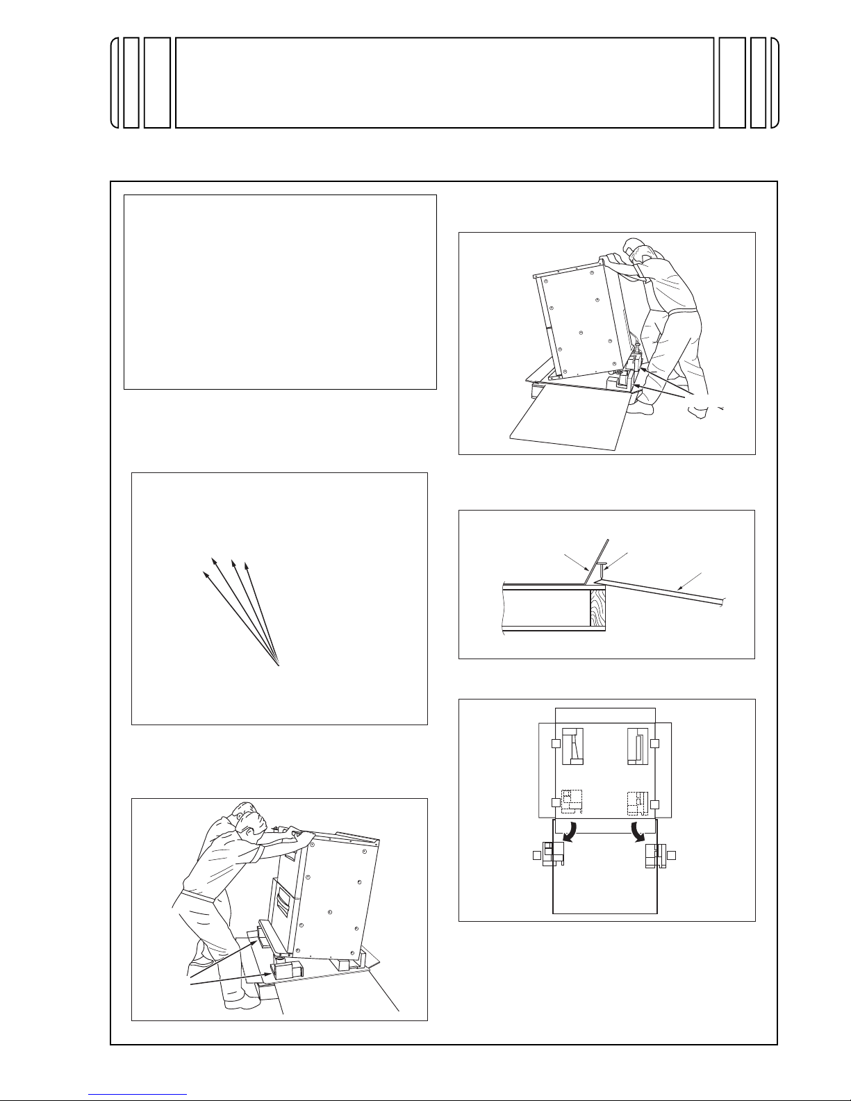
I.Directions for Placing the Machine on the Flo or
Note:
When moving the PF-602, do not hold the area
indicated in the photograph below.
Note:
Make sure to conduct the procedure at each person.
1. Raising the front side of PF-602, to remove the 2
cushions.
2. Raising the back side of PF-602, remove the 2
cushions.
3. Fix the veneer with its beveled portion turned
upward, to the right end face of the pallet by nails
as illustrated below.
4. Set the 2 cushions removed from the machine,below
the veneer as illustrated below.
00AAIXE000SAA03XIXJ001CBA03XIXJ001CBA03XIXE001CC
Do not hold here
A03XIXE017SA
Cushions
A03XIXE018SA
Cushions
Nails : 2 pcs.
Veneer
Corrugated fiberboard
A03XIXE019SA
A D
C
B
B C
A03XIXC014SA
Applied Machine: C6501/C6501P/C65hc/C7000/C7000P/C6000/C70hc
COLOR MFP: 65ppm COLOR PRESS: (71ppm/71ppm)/(70ppm/70ppm)/(60ppm/60ppm)
Product Code: A0U0/A0U2/A0Y8/A1DU/A204/A1DV/A205
Page 2
E-2
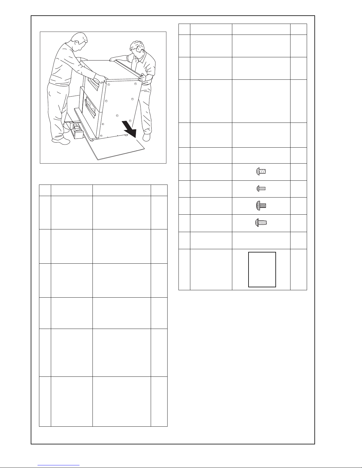
5. Gently bring down the machine onto the floor.
II.Accessory parts
No. Name Shape Q’ty
1. Installation
plate/1
A03XIXC001SA
1
2. Installation
plate/2
A03XIXC002SA
1
3. Fixing pin/1
A03XIXC003SA
1
4. Fixing pin/2
A03XIXC004SA
1
5. Paper path
attachment
A03XIXC005SA
1
6. Connector
cover
A03XIXC006SA
1
A03XIXC015SA
7. Top cover/A
A03XIXC007SA
1
8. Cushion/1
(Not used on the
Printer Model)
A03XIXC009SA
2
9. Seal/P
A03XIXC018SB
2
10. Cushion/2
A03XIXC008SA
1
11. Spanner
A03XIXC011SA
1
12. TP screw M4x6
6
13. TP screw M3x6
2
14. Truss screw
(black) M4x6
3
15. B tight screw
M4x8
3
16. Nail
2
17. Installation
manual
1
No. Name Shape Q’ty
Page 3
E-3
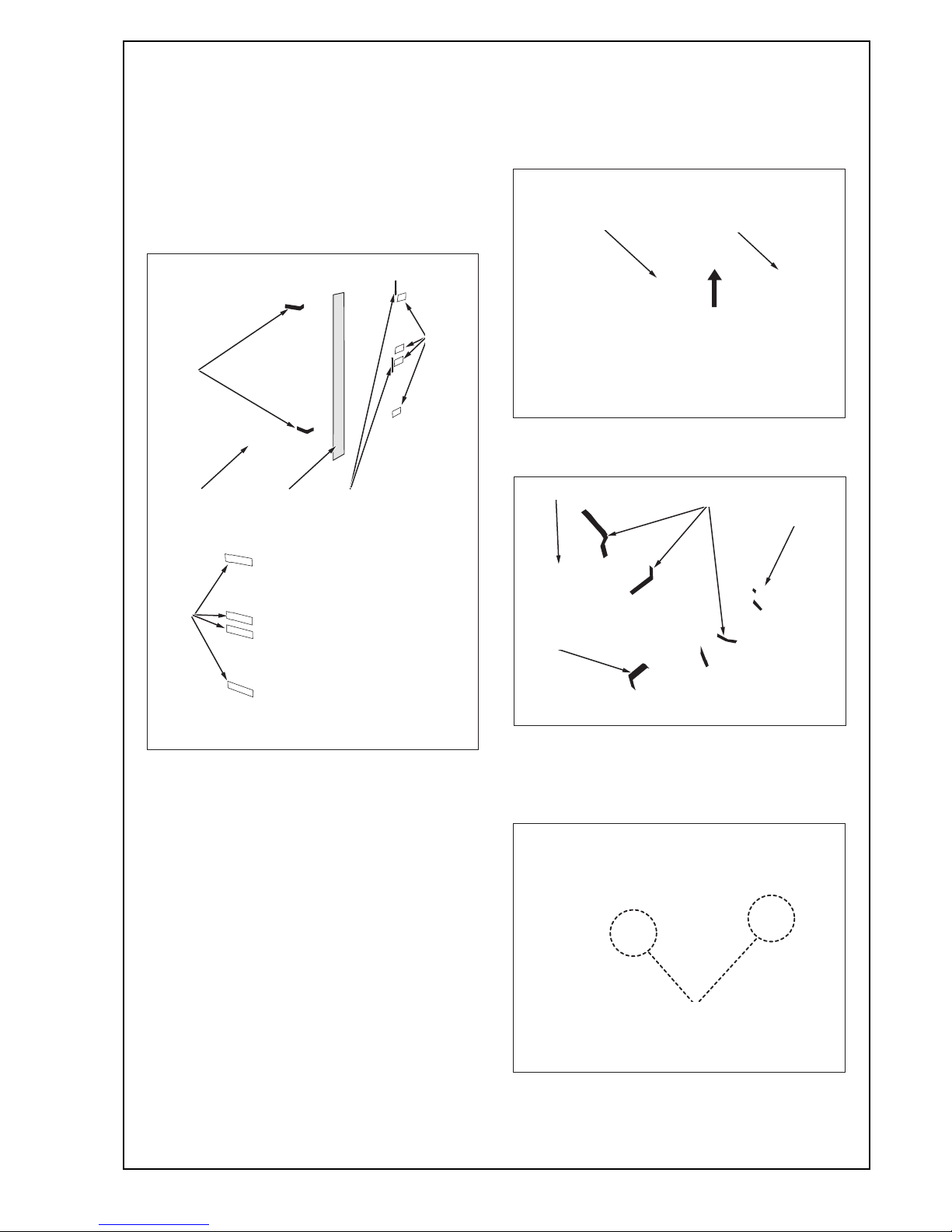
III.Installation Procedure
1. Visually inspect the outside of the Paper feeder
unit, and remove locking tapes and protection
paper.
Note:
• Locking guide tapes indicate the portions to be
unlocked; those tapes should be removed after
the completion of each unlocking procedure.
• Being to be a lock tape even in the front door,with-
out forgetting, you remove.
2. Remove the locking tapes within the trays.
(1) Open the front door and remove locking tapes
of PF1, PF2, PF5 and Filter lever.
(2) Open the PF1 door and pull tray 4 out while
pushing the lock lever up on the left side of the
tray.
(3) Remove the locking tapes and the cushions
inside tray 4. Remove the locking guide tape
as the last step.
(4) Repeat procedures for tray 5 and close the
PF1 door and the front door.
3. Cut off the split covers on the right side of the
machine with a nipper. (2 plates)
(Exclusive the Printer Model)
A03XIXE002CA
Locking
tapes
Locking
tapes
Locking
tapes
Locking guide tapes
Accessory
parts
Protector
sheet
A03XIXE029SA
Front door
PF1 door
A03XIXE003SA
Locking tapes
Locking guide tape
Cushion
Cushion
A03XIXE004SA
Split cover
Page 4

E-4
4. Attach the cushion/1. (2 cushions)
(Exclusive the Printer Model)
5. Remove the right cover/2. (1 screw)
6. Remove the right cover/3. (2 screws)
Note:
Remember to remove the right cover.
7. Install the paper path attachment with the 2
screws removed in step 6.
8. Cut off the 4 split covers on the right side of the
machine with a nipper. (1 screw removed)
9. Install the installation plate/1 and installation
plate/2 with 2 screws apiece. (TP screw M4x6: 4
pcs.)
A03XIXE005SA
Cushion/1
A03XIXE006SA
Right cover/2
A03XIXE007SA
Right cover/3
A03XIXE008SA
Paper path attachment
Removed screws
A03XIXE009SA
Screw
Split covers
A03XIXE010SA
Installation plate/1
Installation plate/2
Page 5

E-5
10. Pull out the connector plate.(2 screws)
11. Affix the seal/P on the top cover.(2 seals)
12. Loosely attach the top cover/A with the face of
the PF top cover.(B tight screw M4x8: 3pcs.)
13. Connect the PF-602 connector s (3) to the m achine.
14. Joint temporary the connector plate and wire
relay bracket to the machine by the 2 screws
removed in step 10.
15. Fix the connector plate and wire relay bracket
together.(TP screw M3x6: 2pcs.)
16. Tighten fully the 2 screws jointed in step 14.
A03XIXE011SA
Connector plate
Align to the right hand edge and
the bottom of the top cover
Seal/P
A03XIXE033SB
00AAIXE000SAA03XIXE003CB
Top cover/A
B tight screws M4x8
A03XIXE014SA
Connectors
Machine
PF
A03XIXE004CB
Machine
Removed screws
TP screw
M3x6: 2pcs.
Connector plate
Wire relay bracket
A03XIXE005CA
Page 6

E-6
17. Set the PF-602 onto the machine. Clamp the
machine installation plate/2 with the PF-602
installation plate.
18. Adjust the PFU adjusters (4) to make sure the
pin hole on installation plates/1 and 2, which
were attached to the machine line up with the
installation plates from PF-602.
(1) Remove the PF-602 back cover/2. (9 screws)
(2) Adjust with a spanner.
(3) Pull out the upper tray and check if the gap
between the PFU frame and tray guide board
is 2mm and more. If the gap is less than 2mm,
adjust the gap by raising the two adjusters of
the PFU right side.
19. Fix the PF-602 to the machine.
(1) Fix the PF-602 and the installation plate on the
machine using fixing pin/1. (TP screw M4x6: 1
pc.)
(2) Fix the back side of the PF-602 with fixing pin/
2. (TP screw M4x6: 1 pc.)
(3) Attach the PF-602 back cover/2. (9 screws)
A03XIXE020SA
Installation plate
Installation plate/2
Machine
PF
Pin hole
A03XIXE021SA
Back cover/2
A03XIXC016SA
A03XIXE031SA
Gaps being more than 2mm.
PFU frame
Tray guide board
PFU frame
Tray guide board
A03XIXE022SA
Fixing pin/1
TP screw M4x6
A03XIXE023SA
TP screw M4x6
Fixing pin/2
Back side
Page 7

E-7
20. Align the top cover with the machine and tighten
the screws.
21. Affix cushion/2 to top cover A.
22. Rotate the filter lever as indicated below and
press the screw in to affix.
23. Install the connector cover. [Truss screw (black)
M4x6: 3 pcs.]
Align with the machine
Tighten
A03XIXE024SB
A03XIXE030SB
Coussin/2
A03XIXE025SA
Filter lever
Screw position
A03XIXE026SA
Connector cover
Truss screw(black)
M4x6
Page 8

E-8
IV.Serial Number Registration
Register the serial number of the PF-602 installed to
the machine.
The location of the serial number is shown in the figure below.
[C6501/C6501P/C65hc]
[C7000/C7000P/C6000/C70hc]
V.Centering Check
Place paper in each tray of the PF-602.
Check that the printed image is centered on the
page for each tray of the PF-602.
If the image is off-center, refer to the service manual
to correct it.
Step
1. Plug the power cord into the outlet and turn
ON the Main power switch.
2. Enter Service mode.
Note:
Refer to procedures in the Service Manual to
enter into the Service Mode.
3. [Service Mode Menu screen]
Touch “System setting”.
4. [System Setting Menu screen]
Touch “M/C Serial Number Setting”.
5. Touch “Option tray” according to the place
where it was installed to display the Serial
number entry screen.
6. Enter the serial number of the PF-602 and
touch “OK”. (Use “Shift” to switch between
upper case letters and lower case letters.)
7. Touch “Return” on the serial number list screen.
8. Touch “Exit”.
A03XIXE032SB
Serial No.
Step
1. Plug the power cord into the outlet and turn
ON the Main power switch.
2. Enter Service mode.
Note:
Refer to procedures in the Service Manual to
enter into the Service Mode.
3. Touch “System Setting”.
4. Touch “Serial Number Setting”.
5. Touch “Option tray” according to the place
where it was installed to display the serial
number setting screen. (Select the installation order key.)
6. Enter the serial number of the PF-602 and
touch “OK”. (Use “Shift” to switch between
upper case letters and lower case letters.)
7. Touch the "Return" key, then touch the "Exit"
key.
 Loading...