

Page 1

ineo 250/350
Dynamic balance
www.d evelop.d e
Service Manual Field
Page 2

FIELD SERVICE TOTAL CONTENTS
SAFETY AND IMPORTANT WARNING ITEMS ..............................................................S-1
IMPORTANT NOTICE ............................................................................................... .S-1
DESCRIPTION ITEMS FOR DANGER, WARNING AND CAUTION .........................S-1
SAFETY WARNINGS .................................................................................................S-2
WARNING INDICATIONS ON THE MACHINE ........................................................S-17
MEASURES TO TAKE IN CASE OF AN ACCIDENT ....................................................S-20
Composition of the service manual ................................................................................. C-1
Notation of the service manual ....................................................................................... C-2
bizhub 200/250/350 Main Unit
General...........................................................................................................................1
Maintenance ................................................................................................................... 7
Adjustment/Setting......................................................................................................111
Troubleshooting...........................................................................................................221
Appendix.....................................................................................................................273
Duplex Unit/Switchback Unit
General...........................................................................................................................1
Maintenance ................................................................................................................... 3
Adjustment/Setting..........................................................................................................7
Troubleshooting.............................................................................................................11
Standard Controller
General...........................................................................................................................1
Maintenance ................................................................................................................... 3
Troubleshooting...............................................................................................................5
FK-503
General...........................................................................................................................1
Maintenance ................................................................................................................... 5
Adjustment/Setting........................................................................................................11
Troubleshooting...........................................................................................................161
DF-605
General...........................................................................................................................1
Maintenance ................................................................................................................... 5
Adjustment/Setting........................................................................................................17
Troubleshooting.............................................................................................................27
i
Page 3

PC-102/PC-202
General........................................................................................................................... 1
Maintenance................................................................................................................... 3
Adjustment/Setting ....................................................................................................... 13
Troubleshooting............................................................................................................ 21
PC-402
General........................................................................................................................... 1
Maintenance................................................................................................................... 3
Adjustment/Setting ....................................................................................................... 17
Troubleshooting............................................................................................................ 25
JS-502
General........................................................................................................................... 1
Maintenance................................................................................................................... 3
Adjustment/Setting ......................................................................................................... 5
FS-508/PU-501/OT-601
General........................................................................................................................... 1
Maintenance................................................................................................................... 5
Adjustment/Setting ....................................................................................................... 23
Troubleshooting............................................................................................................ 35
MT-501
General........................................................................................................................... 1
Maintenance................................................................................................................... 3
Adjustment/Setting ......................................................................................................... 7
Troubleshooting............................................................................................................ 11
SD-502
General........................................................................................................................... 1
Maintenance................................................................................................................... 3
Adjustment/Setting ....................................................................................................... 19
Troubleshooting............................................................................................................ 27
ii
Page 4
SAFETY AND IMPORTANT WARNING ITEMS
SAFETY AND IMPORTANT WARNING ITEMS
Read carefully the Safety and Important Warning Items described below to understand
them before doing service work.
IMPORTANT NOTICE
Because of possible hazards to an inexperienced person servicing this product as well as
the risk of damage to the product, KONICA MINOLTA BUSINESS TECHNOLOGIES, INC.
(hereafter called the KMBT) strongly recommends that all servicing be performed only by
KMBT-trained service technicians.
Changes may have been made to this product to impro ve its perf ormance after this Service
Manual was printed. Accordingly, KMBT does not warrant, either explicitly or implicitly, that
the information contained in this Service Manual is complete and accurate.
The user of this Service Manual must assume all risks of personal injury and/or damage to
the product while servicing the product for which this Service Manual is intended.
Therefore, this Service Manual must be carefully read before doing service work both in the
course of technical training and even after that, for performing maintenance and control of
the product properly.
Keep this Service Manual also for future service.
DESCRIPTION ITEMS FOR DANGER, WARNING AND CAUTION
In this Service Manual, each of three expressions “ DANGER”, “ WARNING”, and
“ CAUTION” is defined as follows together with a symbol mark to be used in a limited
meaning.
When servicing the product, the relevant works (disassembling, reassembling, adjustment,
repair, maintenance, etc.) need to be conducted with utmost care.
DANGER: Action having a high possibility of suffering death or serious injury
WARNING:Action having a possibility of suffering death or serious injury
CAUTION: Action having a possibility of suffering a slight wound, medium
trouble, and property damage
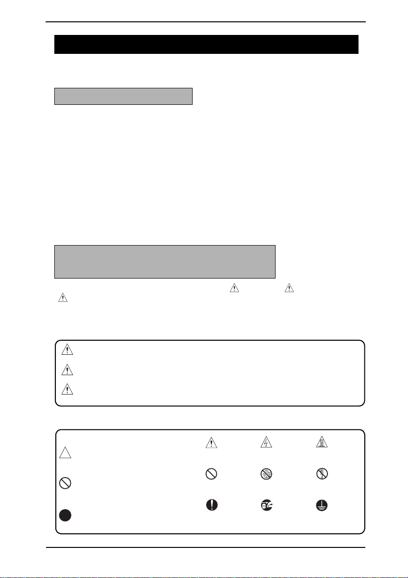
Symbols used for safety and important warning items are defined as follows:
:Precaution when servicing
the product.
:Prohibition when servicing
the product.
:Direction when servicing the
product.
General
precaution
General
prohibition
General
instruction
Electric hazard High
Do not touch
with wet hand
Unplug Ground/Earth
temperature
Do not
disassemble
S-1
Page 5
SAFETY AND IMPORTANT WARNING ITEMS
SAFETY WARNINGS
[1] MODIFICATIONS NOT AUTHORIZED BY KONICA MINOLTA
BUSINESS TECHNOLOGIES, INC.
KONICA MINOLTA brand products are renowned for their high reliability. This reliability is
achieved through high-quality design and a solid service network.
Product design is a highly complicated and delicate process where numerous mechanical,
physical, and electrical aspects have to be tak en into consideration, with the aim of arriving
at proper tolerances and safety factors. For this reason, unauthorized modifications involve
a high risk of degradation in performance and safety. Such modifications are therefore
strictly prohibited. the points listed below are not exhaustive, but they illustrate the reasoning behind this policy.
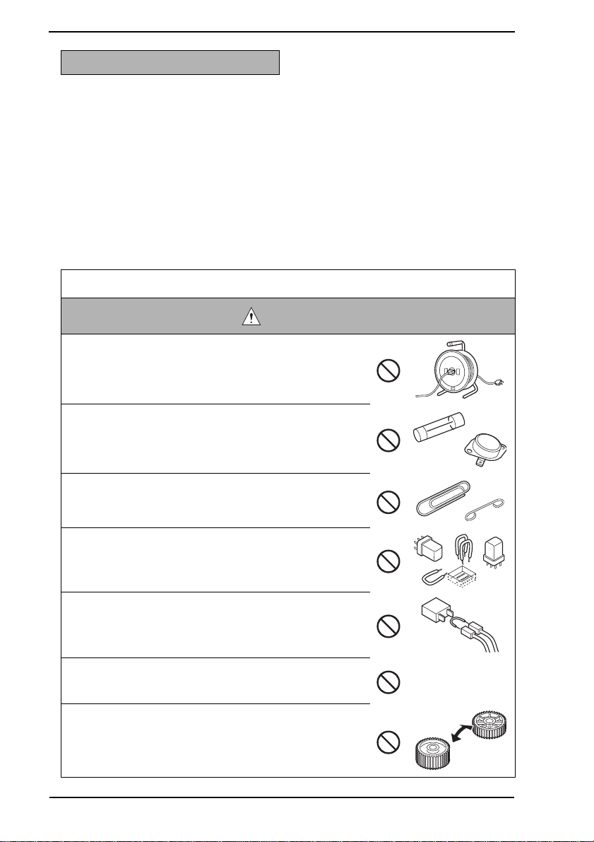
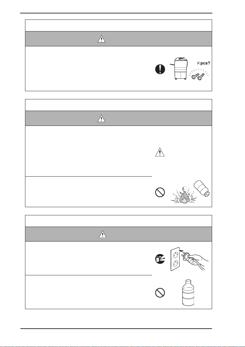
Prohibited Actions
DANGER
• Using any cables or power cord not specified by KMBT.
• Using any fuse or thermostat not specified by KMBT.
Safety will not be assured, leading to a risk of fire and
injury.
• Disabling fuse functions or bridging fuse terminals with
wire, metal clips, solder or similar object.
• Disabling relay functions (s uch as wedging paper between
relay contacts)
• Disabling safety functions (interlocks, safety circuits, etc.)
Safety will not be assured, leading to a risk of fire and
injury.
• Making any modification to the product unless instructed
by KMBT
• Using parts not specified by KMBT
S-2
Page 6
SAFETY AND IMPORTANT WARNING ITEMS
[2] POWER PLUG SELECTION
In some countries or areas, the power plug provided with the product may not fit wall outlet
used in the area. In that case, it is obligation of customer engineer (hereafter called the CE)
to attach appropriate power plug or power cord set in order to connect the product to the
supply.
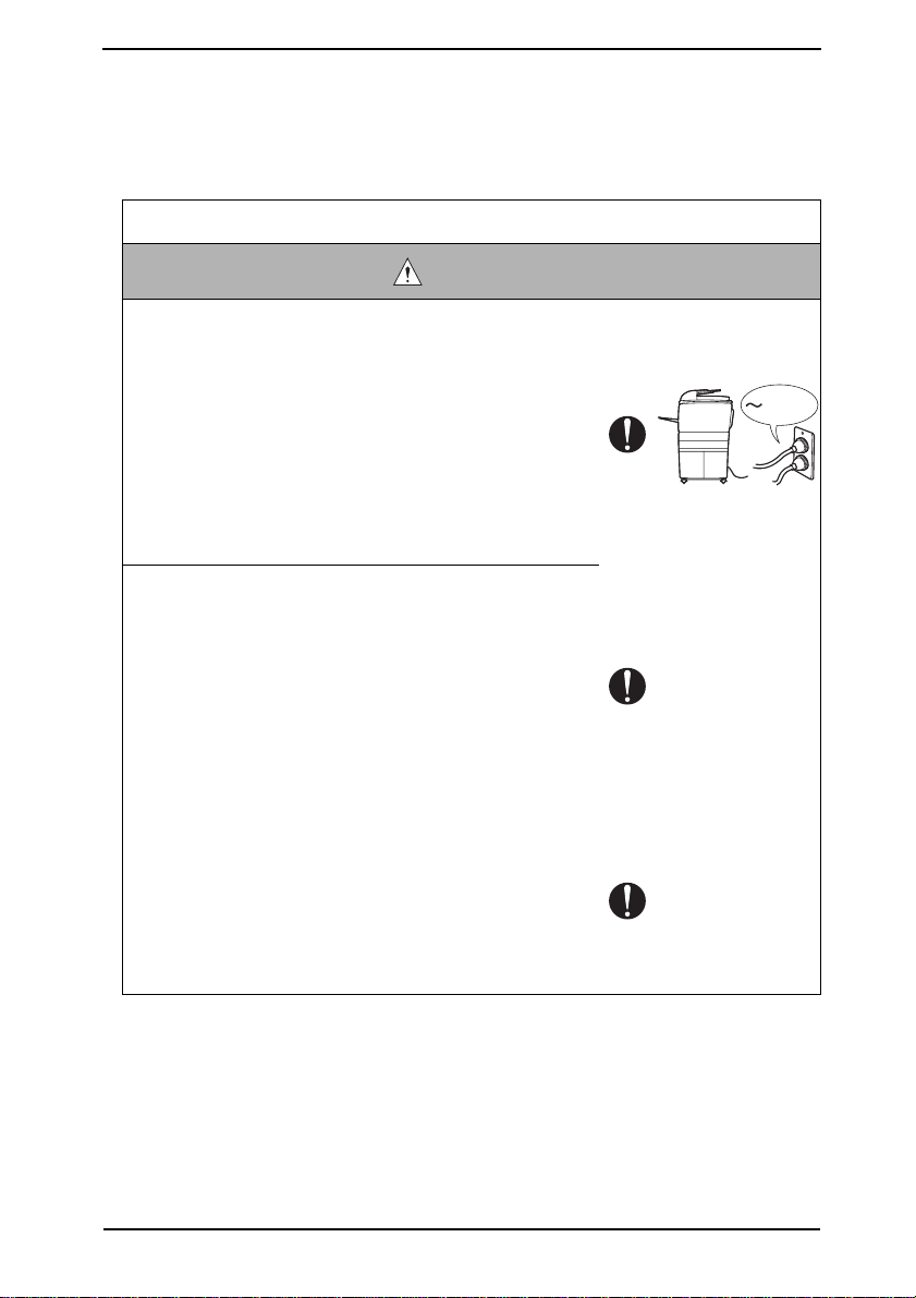
Power Cord Set or Power Plug
WARNING
• Use power supply cord set which meets the following
criteria:
- provided with a plug having configuration intended for
the connection to wall outlet appropriate for the product's rated voltage and current, and
- the plug has pin/terminal(s) for grounding, and
- provided with three-conductor cable having enough current capacity, and
- the cord set meets regulatory requirements for the area.
Use of inadequate cord set leads to fire or electric shock.
• Attach power plug which meets the following criteria:
- having configuration intended for the connection to wall
outlet appropriate for the product's rated voltage and
current, and
- the plug has pin/terminal(s) for grounding, and
- meets regulatory requirements for the area.
Use of inadequate cord set leads to the product connecting to inadequate power supply (voltage, current capacity,
grounding), and may result in fire or electric shock.
• Conductors in the power cable must be connected to terminals of the plug according to the following order:
• Black or Brown: L (line)
• White or Light Blue: N (neutral)
• Green/Yellow: PE (earth)
Wrong connection may cancel safeguards within the
product, and results in fire or electric shock.
kw
S-3
Page 7
SAFETY AND IMPORTANT WARNING ITEMS
[3] CHECKPOINTS WHEN PERFORMING ON-SITE SERVICE
KONICA MINOLT A brand products are e xtensively tested bef ore shipping, to ensure that all
applicable safety standards are met, in order to protect the customer and customer engineer (hereafter called the CE) from the risk of injury. However, in daily use, any electrical
equipment may be subject to parts wear and eventual failure. In order to maintain safety
and reliability, the CE must perform regular safety checks.
1. Power Supply
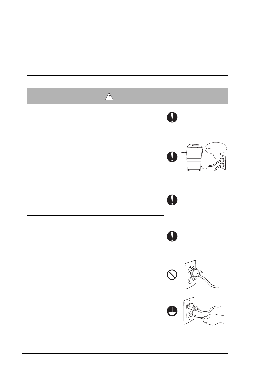
Connection to Power Supply
WARNING
• Check that mains voltage is as specified.
Connection to wrong voltage supply may result in fire or
electric shock.
• Connect power plug directly into wall outlet having same
configuration as the plug.
Use of an adapter leads to the product connecting to
inadequate power supply (voltage, current capacity,
grounding), and may result in fire or electric shock.
If proper wall outlet is not available, advice the customer
to contact qualified electrician for the installation.
• Plug the power cord into the dedicated wall outlet with a
capacity greater than the maximum power consumption.
If excessive current flows in the wall outlet, fire may
result.
• If two or more power cords can be plugged into the wall
outlet, the total load must not exceed the rating of the wall
outlet.
If excessive current flows in the wall outlet, fire may
result.
• Make sure the power cord is plugged in the wall outlet
securely.
Contact problems may lead to increased resistance,
overheating, and the risk of fire.
kw
• Check whether the product is grounded properly.
If current leakage occurs in an ungrounded product, you
may suffer electric shock while operating the product.
Connect power plug to grounded wall outlet.
S-4
Page 8
SAFETY AND IMPORTANT WARNING ITEMS
Power Plug and Cord
WARNING
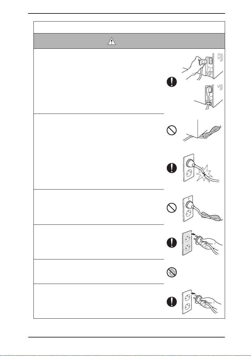
• When using the power cord set (inlet type) that came with
this product, make sure the connector is securely inserted
in the inlet of the product.
When securing measure is provided, secure the cord with
the fixture properly.
If the power cord (inlet type) is not connected to the product securely, a contact problem may lead to increased
resistance, overheating, and risk of fire.
• Check whether the power cord is not stepped on or
pinched by a table and so on.
Overheating may occur there, leading to a risk of fire.
• Check whether the power cord is damaged. Check
whether the sheath is damaged.
If the power plug, cord, or sheath is damaged, replace
with a new power cord (with plug and connector on each
end) specified by KMBT. Using the damaged power cord
may result in fire or electric shock.
• Do not bundle or tie the power cord.
Overheating may occur there, leading to a risk of fire.
• Check whether dust is collected around the power plug
and wall outlet.
Using the power plug and wall outlet without removing
dust may result in fire.
• Do not insert the power plug into the wall outlet with a wet
hand.
The risk of electric shock exists.
• When unplugging the power cord, grasp the plug, not the
cable.
The cable may be broken, leading to a risk of fire and
electric shock.
S-5
Page 9
SAFETY AND IMPORTANT WARNING ITEMS
Wiring
WARNING
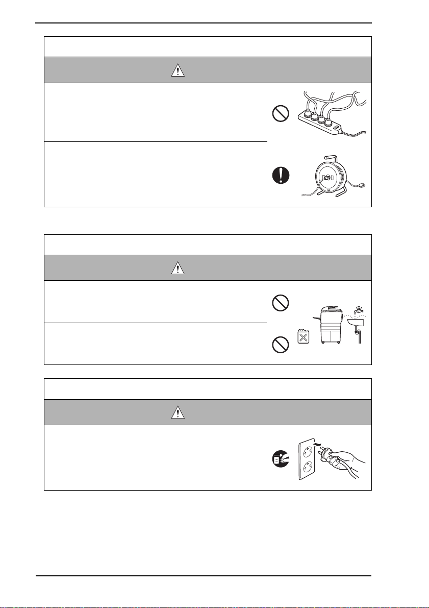
• Never use m ulti-plug adapters to plug multiple power cords
in the same outlet.
If used, the risk of fire exists.
• When an extension cord is required, use a specified one.
Current that can flow in the extension cord is limited, so
using a too long extension cord may result in fire.
Do not use an extension cable reel with the cable taken
up. Fire may result.
2. Installation Requirements
Prohibited Installation Places
WARNING
• Do not place the product near flammable materials or vola-
tile materials that may catch fire.
A risk of fire exists.
• Do not place the product in a place exposed to water such
as rain.
A risk of fire and electric shock exists.
When not Using the Product for a long time
WARNING
• When the product is not used over an extended period of
time (holidays, etc.), switch it off and unplug the power
cord.
Dust collected around the power plug and outlet may
cause fire.
S-6
Page 10
SAFETY AND IMPORTANT WARNING ITEMS
Ventilation
CAUTION
• The product generates ozone gas during operation, but it
will not be harmful to the human body.
If a bad smell of ozone is present in the following cases,
ventilate the room.
a. When the product is used in a poorly ventilated room
b. When taking a lot of copies
c. When using multiple products at the same time
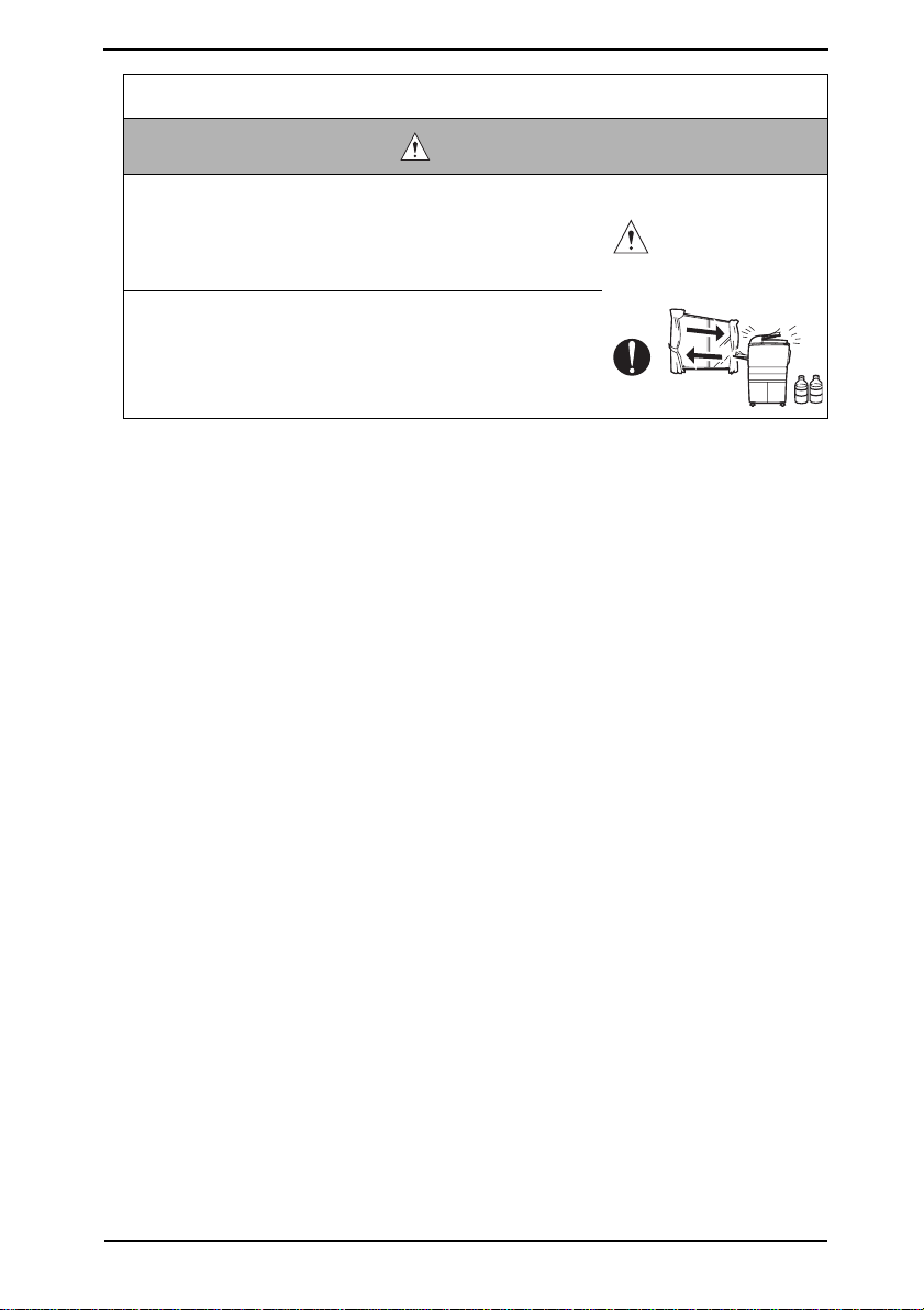
Stability
CAUTION
• Be sure to lock the caster stoppers.
In the case of an earthquake and so on, the product may
slide, leading to a injury.
Inspection before Servicing
CAUTION
• Before conducting an inspection, read all relevant docu-
mentation (service manual, technical notices, etc.) and
proceed with the inspection following the prescribed procedure, using only the prescribed tools. Do not make any
adjustment not described in the documentation.
If the prescribed procedure or tool is not used, the product may break and a risk of injury or fire exists.
• Before conducting an inspection, be sure to disconnect
the power plugs from the product and options.
When the power plug is inserted in the wall outlet, some
units are still powered even if the POWER switch is
turned OFF. A risk of electric shock exists.
• The area around the fixing unit is hot.
You may get burnt.
S-7
Page 11
SAFETY AND IMPORTANT WARNING ITEMS
Work Performed with the Product Powered On
WARNING
• Take every care when making adjustments or performing
an operation check with the product powered.
If you make adjustments or perform an operation check
with the external cover detached, you may touch live or
high-voltage parts or you may be caught in moving gears
or the timing belt, leading to a risk of injury.
• Take every care when servicing with the external cover
detached.
High-voltage exists around the drum unit. A risk of electric shock exists.
Safety Checkpoints
WARNING
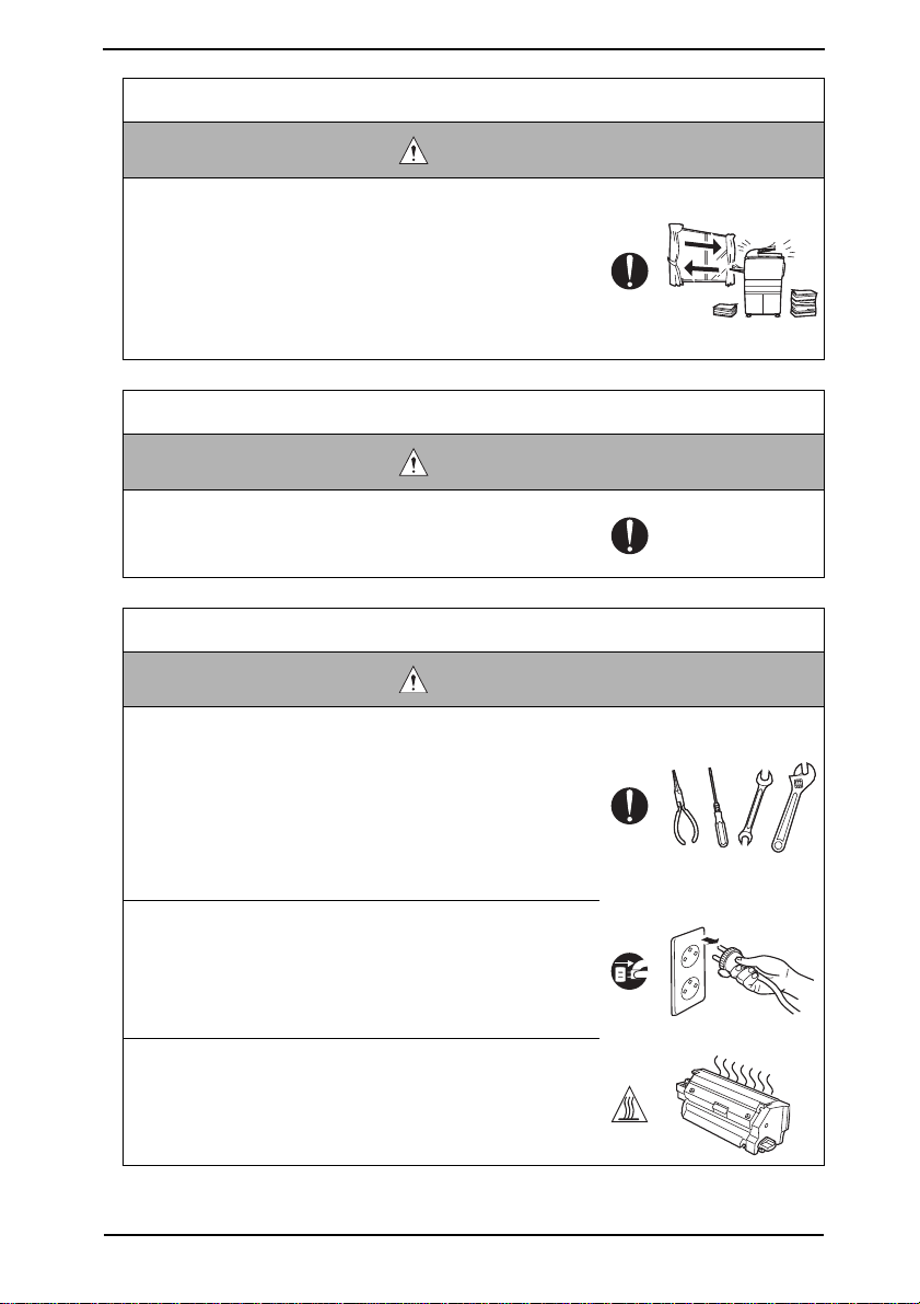
• Check the exterior and frame for edges, burrs, and other
damage.
The user or CE may be injured.
• Do not allow any metal parts such as clips, staples, and
screws to fall into the product.
They can short internal circuits and cause electric shock
or fire.
• Check wiring for squeezing and any other damage.
Current can leak, leading to a risk of electric shock or
fire.
• Carefully remove all toner remnants and dust from electrical parts and electrode units such as a charging corona
unit.
Current can leak, leading to a risk of product trouble or
fire.
• Check high-voltage cables and sheaths for any damage.
Current can leak, leading to a risk of electric shock or
fire.
S-8
Page 12

SAFETY AND IMPORTANT WARNING ITEMS
Safety Checkpoints
WARNING
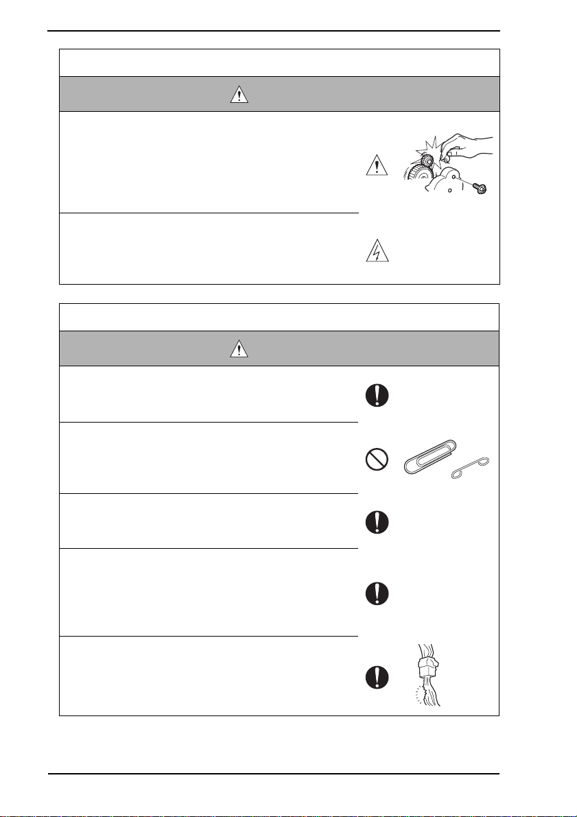
• Check electrode units such as a charging corona unit for
deterioration and sign of leakage.
Current can leak, leading to a risk of trouble or fire.
• Before disassembling or adjusting the write unit (P/H unit)
incorporating a laser, make sure that the power cord has
been disconnected.
The laser light can enter your eye, leading to a risk of
loss of eyesight.
• Do not remove the cover of the write unit. Do not supply
power with the write unit shifted from the specified mounting position.
The laser light can enter your eye, leading to a risk of
loss of eyesight.
• When replacing a lithium battery, replace it with a new lithium battery specified in the Parts Guide Manual. Dispose
of the used lithium battery using the method specified by
local authority.
Improper replacement can cause explosion.
• After replacing a part to which AC voltage is applied (e.g.,
optical lamp and fixing lamp), be sure to check the installation state.
A risk of fire exists.
• Check the interlock switch and actuator for loosening and
check whether the interlock functions properly.
If the interlock does not function, you may receive an
electric shock or be injured when you insert your hand in
the product (e.g., for clearing paper jam).
• Make sure the wiring cannot come into contact with sharp
edges, burrs, or other pointed parts.
Current can leak, leading to a risk of electric shock or
fire.
S-9
Page 13
SAFETY AND IMPORTANT WARNING ITEMS
Safety Checkpoints
WARNING
• Make sure that all screws, components, wiring, connectors, etc. that were removed for safety check and maintenance have been reinstalled in the original location. (Pay
special attention to forgotten connectors, pinched cables,
forgotten screws, etc.)
A risk of product trouble, electric shock, and fire exists.
Handling of Consumables
WARNING
• Toner and developer are not harmful substances, but care
must be taken not to breathe excessiv e amounts or let the
substances come into contact with eyes, etc. It may be
stimulative.
If the substances get in the eye, rinse with plenty of water
immediately. When symptoms are noticeable, consult a
physician.
• Never throw the used cartridge and toner into fire.
You may be burned due to dust explosion.
Handling of Service Materials
CAUTION
• Unplug the power cord from the wall outlet.
Drum cleaner (isopropyl alcohol) and roller cleaner (acetone-based) are highly flammable and must be handled
with care. A risk of fire exists.
• Do not replace the cover or turn the product ON before
any solvent remnants on the cleaned parts have fully
evaporated.
A risk of fire exists.
S-10
Page 14
SAFETY AND IMPORTANT WARNING ITEMS
Handling of Service Materials
CAUTION
• Use only a small amount of cleaner at a time and take
care not to spill any liquid. If this happens, immediately
wipe it off.
A risk of fire exists.
• When using any solvent, ventilate the room well.
Breathing large quantities of organic solvents can lead to
discomfort.
S-11
Page 15

SAFETY AND IMPORTANT WARNING ITEMS
[4] Used Batteries Precautions
ALL Areas
CAUTION
Danger of explosion if battery is incorrectly replaced.
Replace only with the same or equivalent type recommended by the manufacturer.
Dispose of used batteries according to the manufacturer’s instructions.
Germany
VORSICHT!
Explosionsgefahr bei unsachgemäßem Austausch der Batterie.
Ersatz nur durch denselben oder einen vom Hersteller empfohlenen gleichwertigen Typ.
Entsorgung gebrauchter Batterien nach Angaben des Herstellers.
France
ATTENTION
Il y a danger d’explosion s’il y a remplacement incorrect de la batterie.
Remplacer uniquement avec une batterie du même type ou d’un type équivalent recommandé par le constructeur.
Mettre au rebut les batteries usagées conformément aux instructions du fabricant.
Denmark
Lithiumbatteri - Eksplosionsfare ved fejlagtig håndtering.
Udskiftning må kun ske med batteri af samme fabrikat og type.
Levér det brugte batteri tilbage til leverandøren.
Finland, Sweden
Paristo voi räjähtää, jos se on virheellisesti asennettu.
Vaihda paristo ainoastaan laitevalmistajan suosittelemaan tyyppiin.
Hävitä käytetty paristo valmistajan ohjeiden mukaisesti.
ADVARSEL!
VAROlTUS
VARNING
Explosionsfara vid felaktigt batteribyte.
Använd samma batterityp eller en ekvivalent typ som rekommenderas av apparattillverkaren.
Kassera använt batteri enligt fabrikantens instruktion.
Norway
Eksplosjonsfare ved feilaktig skifte av batteri.
Benytt samme batteritype eller en tilsvarende type anbefalt av apparatfabrikanten.
Brukte batterier kasseres i henhold til fabrikantens instruksjoner.
ADVARSEL
S-12
Page 16
SAFETY AND IMPORTANT WARNING ITEMS
[5] Laser Safety
• This is a digital machine certified as a class 1 laser product. There is no possibility of
danger from a laser, provided the machine is serviced according to the instruction in this
manual.
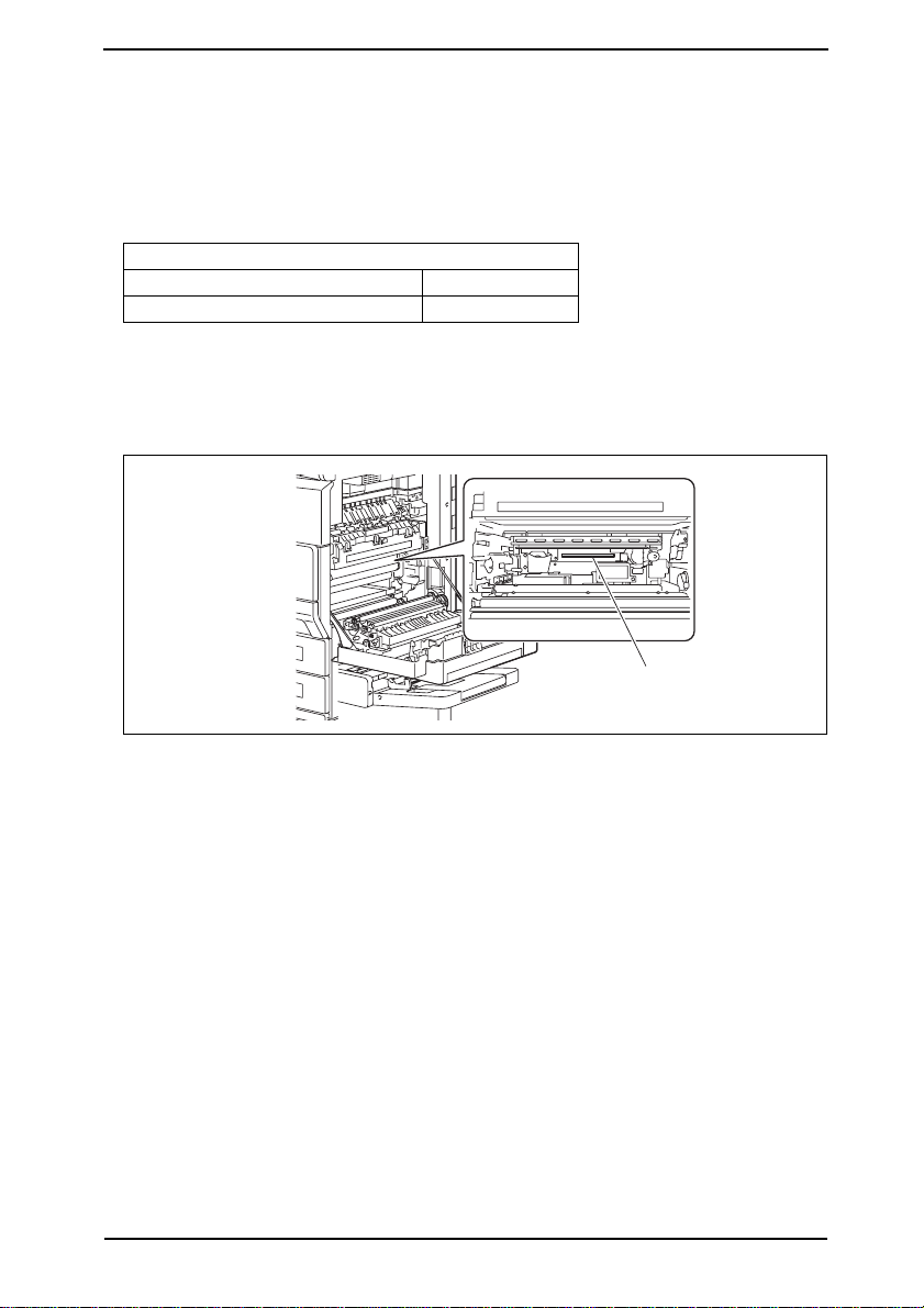
5.1 Internal Laser Radiation
Semiconductor laser
Maximum average radiation power(*) 28.9 µW
Wavele ngth 770-795 nm
*:Laser Aperture of the Print Head Unit
• This product employs a Class 3b laser diode that emits an invisible laser beam. The laser
diode and the scanning polygon mirror are incorporated in the print head unit.
• The print head unit is NOT A FIELD SERVICE ITEM. Therefore, the print head unit
should not be opened under any circumstances.
Laser Aperture of
the Print Head Unit
4040P0C504DA
S-13
Page 17

SAFETY AND IMPORTANT WARNING ITEMS
the U.S.A., Canada (CDRH Regulation)
• This machine is certified as a Class I Laser product under Radiation Performance Standard according to the Food, Drug and Cosmetic Act of 1990. Compliance is mandatory
for Laser products marketed in the United States and is reported to the Center for
Devices and Radiological Health (CDRH) of the U.S. Food and Drug Administration of
the U.S. Department of Health and Human Services (DHHS). This means that the device
does not produce hazardous laser radiation.
• The label shown to page S-16 indicates compliance with the CDRH regulations and must
be attached to laser products marketed in the United States.
CAUTION
• Use of controls, adjustments or performance of procedures other than those specified in this manual may result in hazardous radiation exposure.
Semiconductor laser
Maximum power of the laser diode 5 mW
Wavelength 770-795 nm
All Areas
CAUTION
• Use of controls, adjustments or performance of procedures other than those specified in this manual may result in hazardous radiation exposure.
Semiconductor laser
Maximum power of the laser diode 5 mW
Wavelength 770-795 nm
Denmark
ADVARSEL
• Usynlig Laserstråling ved åbning, når sikkerhedsafbrydere er ude af funktion.
Undgå udsættelse for stråling. Klasse 1 laser produkt der opfylder IEC60825 sikkerheds kravene.
Halvlederlaser
Laserdiodens højeste styrke 5 mW
Bølgelængden 770-795 nm
S-14
Page 18

SAFETY AND IMPORTANT WARNING ITEMS
Finland, Sweden
VARO!
• Av attaessa ja suojalukitus ohitettaessa olet alttiina näkymättömälle lasersäteilylle.
Älä katso säteeseen.
LOUKAN 1 LASERLAITE
KLASS 1 LASER APPARAT
VAROITUS!
• Laitteen Käyttäminen muulla kuin tässä käyttöohjeessa mainitulla tavalla saattaa
altistaa käyttäjän turvallisuusluokan 1 ylittävälle näkymättömälle lasersäteilylle.
Puolijohdelaser
Laserdiodin suurin teho 5 mW
Aallonpituus 770-795 nm
VARNING!
• Om apparaten används på annat sätt än i denna bruksanvisning specificerats, kan
användaren utsättas för osynlig laserstrålning, som överskrider gränsen för laserklass 1.
Halvledarlaser
Den maximala effekten för laserdioden 5 mW
Våglängden 770-795 nm
VARNING!
• Osynlig laserstrålning när denna del är öppnad och spärren är urkopplad. Betrakta
ej strålen.
Norway
ADVERSEL
• Dersom apparatet brukes på annen måte enn spesifisert i denne bruksanvisning,
kan brukeren utsettes for unsynlig laserstråling som overskrider grensen for laser
klass 1.
Halvleder laser
Maksimal effekt till laserdiode 5 mW
Bølgelengde 770-795 nm
S-15
Page 19
SAFETY AND IMPORTANT WARNING ITEMS
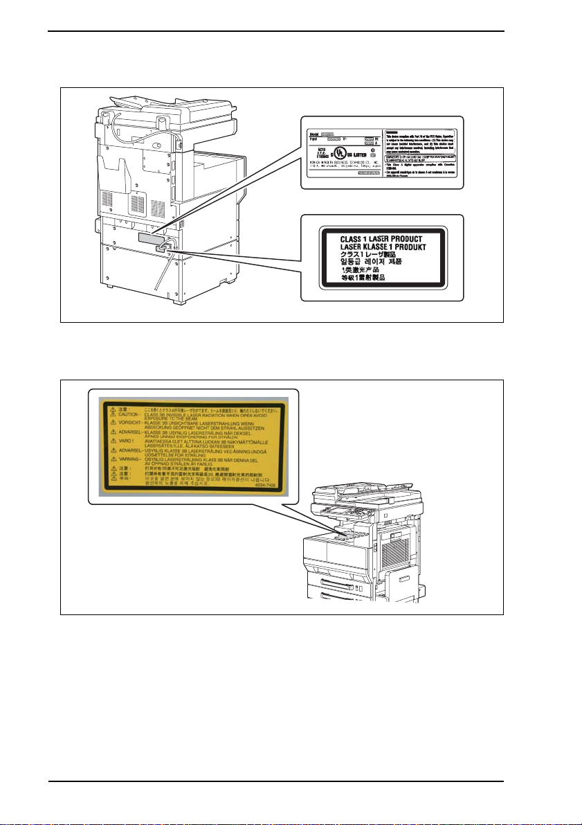
5.2 Laser Safety Label
• A laser safety labels is attached to the outside of the machine as shown below.
* Only for the U.S.A.
5.3 Laser Caution Label
• A laser caution label is attached to the inside of the machine as shown below.
4040P0C506DA
4040P0C503DA
5.4 Precautions For Handling The Laser Equipment
• When laser protective goggles are to be used, select ones with a lens conforming to the
above specifications.
• When a disassembly job needs to be performed in the laser beam path, such as when
working around the printerhead and PC Drum, be sure first to turn the copier OFF.
• If the job requires that the copier be left ON, take off your watch and ring and wear laser
protective goggles.
• A highly reflective tool can be dangerous if it is brought into the laser beam path. Use
utmost care when handling tools on the user’s premises.
S-16
Page 20
SAFETY AND IMPORTANT WARNING ITEMS
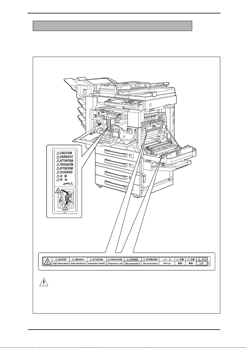
WARNING INDICATIONS ON THE MACHINE
Caution labels shown are attached in some areas on/in the machine.
When accessing these areas for maintenance, repair, or adjustment, special care should
be taken to avoid burns and electric shock.
CAUTION
4040P0C500DA
S-17
Page 21
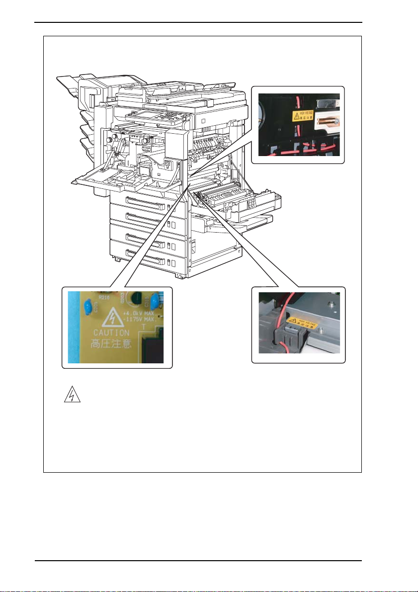
SAFETY AND IMPORTANT WARNING ITEMS
S-18
High voltage
4040P0C501DA
Page 22
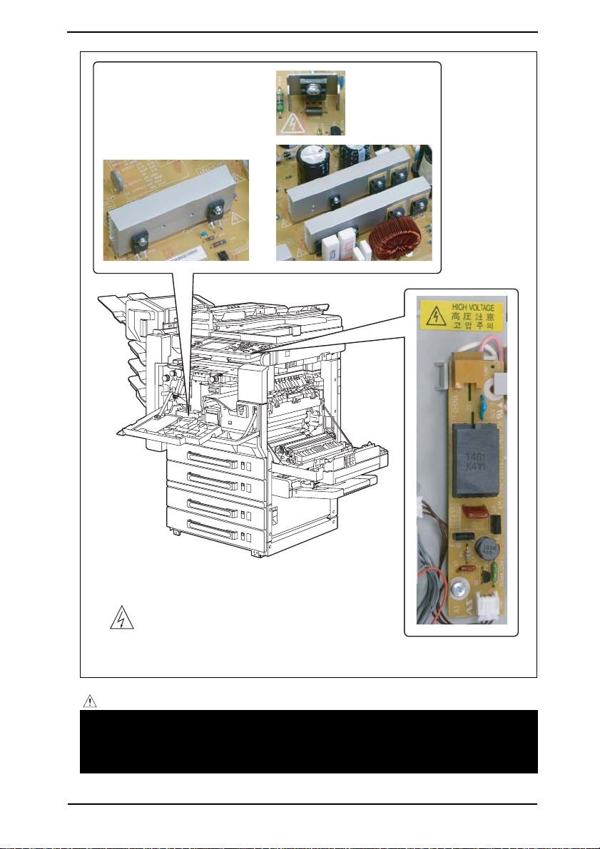
SAFETY AND IMPORTANT WARNING ITEMS
High voltage
4040P0C505DA
CAUTION:
• You may be burned or injured if you touch any area that you are advised not to
touch by any caution label. Do not remove caution labels. If any caution label has
come off or soiled and therefore the caution cannot be read, contact our Service
Office.
S-19
Page 23

MEASURES TO TAKE IN CASE OF AN ACCIDENT
MEASURES TO TAKE IN CASE OF AN
ACCIDENT
1. If an accident has occurred, the distributor who has been notified first must immediately
take emergency measures to provide relief to affected persons and to prevent further
damage.
2. If a report of a serious accident has been received from a customer, an on-site evaluation must be carried out quickly and KMBT must be notified.
3. To determine the cause of the accident, conditions and materials must be recorded
through direct on-site checks, in accordance with instructions issued by KMBT.
4. For reports and measures concerning serious accidents, follow the regulations specified by every distributor.
S-20
Page 24

Composition of the service manual
This service manual consists of Theory of Operation section and Field Service section to
explain the main machine and its corresponding options.
Theory of Operation section gives, as information for the CE to get a full understanding of
the product, a rough outline of the object and role of each function, the relationship
between the electrical system and the mechanical system, and the timing of operation of
each part.
Field Service section gives, as information required by the CE at the site (or at the customer’s premise), a rough outline of the service schedule and its details, maintenance
steps, the object and role of each adjustment, error codes and supplementary information.
The basic configuration of each section is as follows. However some options may not be
applied to the following configuration.
<Theory of Operation section>
OUTLINE: Explanation of system configuration,
product specifications, unit configuration, and paper path
COMPOSITION/OPERATION: Explanation of configuration of each unit,
operating system, and control system
<Field service section>
GENERAL: Explanation of system configuration, and product
specifications
MAINTENANCE: Explanation of service schedule, maintenance steps, ser-
vice tools, removal/reinstallation methods of major parts,
and firmware version up method etc.
ADJUSTMENT/SETTING: Explanation of utility mode, service mode, and mechanical
adjustment etc.
TROUBLESHOOTING: Explanation of lists of jam codes and error codes, and
their countermeasures etc.
APPENDIX: Parts layout drawings, connector layout drawings, timing
chart, overall layout drawing are attached.
C-1
Page 25

Notation of the service manual
A. Product name
In this manual, each of the products is described as follows:
(1) IC board: Standard printer
bizhub 200/250/350: Main body
(2)
(3) Microsoft Windows 95: Windows 95
Microsoft Windows 98: Windows 98
Microsoft Windows Me: Windows Me
Microsoft Windows NT 4.0: Windows NT 4.0 or Windows NT
Microsoft Windows 2000: Windows 2000
Microsoft Windows XP: Windows XP
When the description is made in combination of the OS’s mentioned above:
Windows 95/98/Me
Windows NT 4.0/2000
Windows NT/2000/XP
Windows 95/98/Me/ NT/2000/XP
B. Brand name
The company names and product names mentioned in this manual are the brand name or
the registered trademark of each company.
C-2
Page 26

ineo 250/350
Main Unit
Dynamic balance
www.d evelop.d e
Service Manual Field
Page 27

Revision history
After publication of this service manual, the parts and mechanism may be subject to change for
improvement of their performance.
Therefore, the descriptions given in this service manual may not coincide with the actual machine.
When any change has been made to the descriptions in the service manual, a revised version will be
issued with a revision mark added as required.
Revision mark:
• To indicate clearly a section revised, show to the left of the revised section.
A number within represents the number of times the revision has been made.
1
1
• To indicate clearly a section revised, show in the lower outside section of the corresponding page.
A number within represents the number of times the revision has been made.
NOTE
Revision marks shown in a page are restricted only to the latest ones with the old ones deleted.
• When a page revised in Ver. 2.0 has been changed in Ver. 3.0:
The revision marks for Ver. 3.0 only are shown with those for Ver. 2.0 deleted.
• When a page revised in Ver. 2.0 has not been changed in Ver. 3.0:
The revision marks for Ver. 2.0 are left as they are.
1
1
2005/08 1.0 — Issue of the first edition
Date Service manual Ver. Revision mark Descriptions of revision
Page 28

Field Service Ver. 1.0 Aug. 2005
CONTENTS
bizhub 200/250/350 Main Unit
General
1. System configuration............................................................................................... 1
2. Product specifications ............................................................................................. 3
3. Built-in Controllers...................................................................................................5
Maintenance
4. Periodical check.................................................................................................. .... 7
4.1 Service schedule .................................................................................................. 7
4.1.1 bizhub 350 ....................................................................................................7
4.1.2 bizhub 250 ....................................................................................................7
4.1.3 bizhub 200 ....................................................................................................7
4.1.4 Option ...........................................................................................................8
4.2 Maintenance items................................................................................................ 8
4.2.1 bizhub 350 ....................................................................................................8
4.2.2 bizhub 250 ..................................................................................................10
4.2.3 bizhub 200 ..................................................................................................13
4.3 Maintenance parts..............................................................................................15
4.3.1 Replacement parts...................................................................................... 15
4.3.2 Cleaning parts............................................................................................. 16
4.4 Concept of parts life............................................................................................17
4.5 Maintenance procedure (Periodical check parts) ...............................................18
4.5.1 Replacing the Bypass Tray Feed Roller...................................................... 18
4.5.2 Replacing the Bypass Tray Separation Roller Assy....................................19
4.5.3 Replacing the Tray 1 Feed Roller................................................................20
4.5.4 Replacing the Tray 1 Pick-up Roller............................................................21
4.5.5 Replacing the Tray 1 Separation Roller Assy..............................................23
4.5.6 Replacing the Tray 2 Feed Roller................................................................25
4.5.7 Replacing the Tray 2 Pick-up Roller............................................................26
4.5.8 Replacing the Tray 2 Separation Roller....................................................... 28
4.5.9 Replacing of the Registration Roller Bearings and
Registration Roller Gears 1, 2.....................................................................30
4.5.10 Cleaning of the Paper Dust Remover..........................................................31
4.5.11 Replacing of the Toner Filter (Developing Unit)........................................... 32
4.5.12 Replacing of the Toner Filter (Main Unit).....................................................33
bizhub 200/250/350GeneralMaintenanceAdjustment / Setting
Troubleshooting
Appendix
i
Page 29

4.5.13 Replacement of the Ozone Filter................................................................33
4.5.14 Replacement of the Developer ................................................................... 34
4.6 Replacing the unit............................................................................................... 37
4.6.1 Replacement of the Fusing Unit ................................................................. 37
bizhub 200/250/350
4.6.2 Replacement of the Transfer Roller Unit..................................................... 38
4.6.3 Replacement of the Photo Conductor Unit ................................................. 39
4.6.4 Replacement of the Developing Unit .......................................................... 40
5. Service tool........................................................................................................... 41
5.1 CE Tool list .........................................................................................................41
GeneralMaintenanceAdjustment / Setting
5.2 Copy materials ................................................................................................... 41
5.2.1 Developer.................................................................................................... 41
5.2.2 Photo Conductor Unit ................................................................................. 41
5.2.3 Toner Bottle................................................................................................. 41
6. Firmware upgrade................................................................................................. 42
6.1 Preparations for Firmware rewriting ................................................................... 42
6.1.1 Service environment................................................................................... 42
6.1.2 Writing into the Compact flash.................................................................... 42
6.1.3 Checking ROM version............................................................................... 42
6.2 Firmware rewriting.............................................................................................. 42
6.2.1 MSC............................................................................................................ 42
6.2.2 Engine......................................................................................................... 44
7. Other..................................................................................................................... 46
7.1 Disassembly/Adjustment prohibited items.......................................................... 46
7.2 Disassembly/Assembly/Cleaning list (Other parts) ............................................ 47
7.2.1 Disassembly/Assembly parts list ................................................................ 47
7.2.2 Cleaning parts list....................................................................................... 48
7.3 Disassembly/Assembly procedure..................................................................... 49
7.3.1 IR Upper Left Cover/Original Scanning Glass/Front Holding Bracket/
7.3.2 Lower Rear Cover/Lower Right Rear Cover/Tray Rear Cover..................... 49
Troubleshooting
7.3.3 Upper Rear Cover....................................................................................... 50
7.3.4 Rear Right Cover/Front Right Cover........................................................... 50
7.3.5 IR Right Cover/Rear Cover......................................................................... 51
7.3.6 Front Door................................................................................................... 51
7.3.7 Paper Output Cover/Lower Front Cover...................................................... 52
7.3.8 Upper Front Cover/Front Cover................................................................... 53
Appendix
7.3.9 IR Left Cover/Rear Left Cover/Left Cover................................................... 54
7.3.10 Rear Manual Bypass Cover/Front Manual Bypass Cover/
Field Service Ver. 1.0 Aug. 2005
Original Glass............................................................................................. 49
Lower Right Cover...................................................................................... 55
ii
Page 30

Field Service Ver. 1.0 Aug. 2005
7.3.11 Control Panel .............................................................................................. 56
7.3.12 Tray 1 .......................................................................................................... 56
7.3.13 Tray 2 .......................................................................................................... 57
7.3.14 Mechanical Control Board Cover................................................................57
7.3.15 FD Paper Size Board 1...............................................................................58
7.3.16 FD Paper Size Board 2...............................................................................59
7.3.17 Power Supply Unit....................................................................................... 60
7.3.18 High Voltage Unit........................................................................................61
7.3.19 MFBS Board ...............................................................................................62
7.3.20 Inverter Board ............................................................................................. 63
7.3.21 BCRS Board ...............................................................................................64
7.3.22 CCD Unit..................................................................................................... 65
7.3.23 Operation Board..........................................................................................69
7.3.24 Manual Bypass Unit....................................................................................71
7.3.25 PH Unit........................................................................................................71
7.3.26 Toner Hopper Unit.......................................................................................74
7.3.27 Toner Replenishing Drive Unit..................................................................... 74
7.3.28 Duplex Unit.................................................................................................. 76
7.3.29 Switch Back Unit.........................................................................................76
7.3.30 Scanner Motor ............................................................................................77
7.3.31 Exposure Unit .............................................................................................78
7.3.32 Exposure Lamp........................................................................................... 79
7.3.33 Scanner Drive Cables.................................................................................80
7.3.34 Main Motor..................................................................................................85
7.3.35 IU Motor ...................................................................................................... 85
7.3.36 Fusing Unit Cooling Fan Motor ................................................................... 86
7.3.37 Toner Suction Fan Motor.............................................................................86
7.3.38 Temperature/humidity Sensor.....................................................................87
7.3.39 ATDC Sensor .............................................................................................. 87
7.3.40 Thermistor................................................................................................... 89
7.3.41 Paper Exit Roll 1 ......................................................................................... 91
7.3.42 Paper Exit Roll 2 ......................................................................................... 91
7.3.43 Separation Claw..........................................................................................92
7.4 Cleaning procedure ............................................................................................ 94
7.4.1 Manual Bypass Feed Roller........................................................................ 94
7.4.2 Manual Bypass Separation Roller...............................................................94
7.4.3 Tray 1 Feed Roller.......................................................................................95
bizhub 200/250/350GeneralMaintenanceAdjustment / Setting
Troubleshooting
Appendix
iii
Page 31

7.4.4 Tray 1 Pick-up Roller................................................................................... 96
7.4.5 Tray 1 Separation Roller............................................................................. 97
7.4.6 Tray 2 Feed Roller....................................................................................... 98
7.4.7 Tray 2 Pick-up Roller................................................................................... 98
bizhub 200/250/350
GeneralMaintenanceAdjustment / Setting
7.4.8 Tray 2 Separation Roller............................................................................. 99
7.4.9 Registration Roller .................................................................................... 100
7.4.10 Paper Dust Remover ................................................................................ 100
7.4.11 Transport Roller ........................................................................................ 100
7.4.12 Scanner Rails ........................................................................................... 101
7.4.13 Bushings................................................................................................... 101
7.4.14 Mirrors....................................................................................................... 101
7.4.15 Lens.......................................................................................................... 102
7.4.16 Original Scanning Glass ........................................................................... 102
7.4.17 Original Glass ........................................................................................... 102
7.4.18 Charge Neutralizing Plate......................................................................... 103
7.4.19 Ds Collar................................................................................................... 103
7.5 Mount Kit MK-709............................................................................................. 105
7.6 Option counter.................................................................................................. 106
7.6.1 Installation method for the Key Counter.................................................... 106
7.7 Original Size Detecting Sensors....................................................................... 108
7.7.1 Original Size Detecting Sensor Layout..................................................... 108
7.7.2 Mounting of the Original Size Detecting Sensors (Option) ....................... 109
7.8 EEPROM.......................................................................................................... 110
7.8.1 Remounting of the EEPROM.................................................................... 110
Field Service Ver. 1.0 Aug. 2005
Adjustment/Setting
8. How to use the adjustment section..................................................................... 111
9. Utility/Counter Mode ........................................................................................... 112
9.1 Utility/Counter Mode function tree.................................................................... 112
Troubleshooting
Appendix
9.2 Utility/Counter Mode function setting procedure .............................................. 116
9.2.1 Procedure ................................................................................................. 116
9.2.2 Exiting....................................................................................................... 116
9.2.3 Changing the setting value in Utility Mode functions ................................ 116
9.3 Settings in the User Setting.............................................................................. 117
9.3.1 User’s Choice 1/6...................................................................................... 117
9.3.2 User’s Choice 2/6...................................................................................... 118
9.3.3 User’s Choice 3/6...................................................................................... 119
9.3.4 User’s Choice 4/6...................................................................................... 120
iv
Page 32

Field Service Ver. 1.0 Aug. 2005
9.3.5 User’s Choice 5/6......................................................................................121
9.3.6 User’s Choice 6/6......................................................................................123
9.3.7 Store Overlay............................................................................................124
9.4 Settings in the User Management .................................................................... 125
9.4.1 Confirmation Beep .................................................................................... 125
9.4.2 Alarm Volume............................................................................................ 125
9.4.3 Job Complete Beep ..................................................................................125
9.4.4 Panel Cleaning..........................................................................................125
9.4.5 Dehumidify................................................................................................125
9.4.6 Toner Supply............................................................................................. 126
9.5 Settings in the Admin. Management.................................................................127
9.5.1 Initial Setting .............................................................................................127
9.5.2 Admin. Set ................................................................................................127
9.5.3 Account/User Auth....................................................................................128
9.5.4 Call Remote Center ..................................................................................130
9.5.5 Network Setting.........................................................................................130
9.5.6 LDAP Setting............................................................................................. 135
9.5.7 Frame Type Set......................................................................................... 137
9.5.8 Prefix/Suffix Settings.................................................................................138
9.5.9 Printer Setting ........................................................................................... 139
9.5.10 Software SW.............................................................................................139
9.5.11 Ping...........................................................................................................139
9.5.12 Delete Job.................................................................................................139
9.5.13 SSL/TLS....................................................................................................139
9.6 Reports.............................................................................................................140
9.6.1 TX Report..................................................................................................140
9.6.2 RX Report ................................................................................................. 140
9.6.3 One-Touch List.......................................................................................... 140
9.6.4 Mail Program List......................................................................................140
9.7 Settings in the Printer Setting........................................................................... 141
9.7.1 MFP Set....................................................................................................141
9.7.2 Default Set ................................................................................................ 141
9.7.3 PDL Set.....................................................................................................143
9.7.4 Test Print................................................................................................... 144
9.8 Check Detail ..................................................................................................... 144
10. Adjustment item list............................................................................................. 146
11. Tech. Rep. Mode ................................................................................................. 148
11.1 Tech. Rep. Mode function setting procedure .................................................... 148
bizhub 200/250/350GeneralMaintenanceAdjustment / Setting
Troubleshooting
Appendix
v
Page 33

11.2 Tech. Rep. Mode function tree.......................................................................... 149
11.3 Settings in the Tech. Rep. Choice .................................................................... 151
11.3.1 System Set ............................................................................................... 151
11.3.2 Printer ....................................................................................................... 153
bizhub 200/250/350
11.3.3 Sheet-through-ADF................................................................................... 155
11.3.4 The amount of Center Erase .................................................................... 156
11.3.5 Orientation Change................................................................................... 156
11.3.6 Finisher.....................................................................................................156
11.3.7 Trail Erase (Dup)....................................................................................... 156
GeneralMaintenanceAdjustment / Setting
11.4 Table of Temperatures for Adjusting the Fusing Temperature .......................... 157
11.4.1 Standard paper......................................................................................... 157
11.4.2 Special Paper............................................................................................ 158
11.4.3 OHP.......................................................................................................... 158
11.4.4 Thin Paper ................................................................................................ 158
11.5 Settings in the System Input............................................................................. 159
11.5.1 LCT Paper Size......................................................................................... 159
11.5.2 Change Fixed Zoom ................................................................................. 159
11.5.3 Machine Configuration.............................................................................. 159
11.5.4 Technical Memo........................................................................................ 159
11.5.5 Hard Disk.................................................................................................. 159
11.5.6 Original Size Detecting Option.................................................................. 160
11.6 Settings in the Administrator # Initialize............................................................ 160
11.7 Settings in the Counter..................................................................................... 160
11.7.1 Checking the counter reading................................................................... 160
11.7.2 Clearing readings of all counters at once ................................................. 160
11.7.3 Clearing the reading of a specific counter................................................ 160
11.7.4 Paper ........................................................................................................ 160
11.7.5 Jam Counter ............................................................................................. 161
11.7.6 Special Parts Counter............................................................................... 161
Troubleshooting
11.7.7 Service Call Counter................................................................................. 161
11.7.8 Application Counter .................................................................................. 162
11.7.9 Maintenance Counter ............................................................................... 162
11.8 Settings in the Function.................................................................................... 162
11.8.1 F1.............................................................................................................. 162
11.8.2 F2.............................................................................................................. 162
Appendix
11.8.3 F7-1 .......................................................................................................... 162
11.8.4 F7-2 .......................................................................................................... 163
11.8.5 F8.............................................................................................................. 163
Field Service Ver. 1.0 Aug. 2005
vi
Page 34

Field Service Ver. 1.0 Aug. 2005
11.8.6 F12............................................................................................................ 163
11.8.7 Hard Disk Format...................................................................................... 163
11.8.8 FD ............................................................................................................. 164
11.8.9 FC ............................................................................................................. 164
11.8.10 Org. Width Detect Adjust ..........................................................................164
11.8.11 FW Download............................................................................................ 164
11.9 I/O Check..........................................................................................................165
11.9.1 Electrical Components Check Procedure Through Input Data Check ......165
11.9.2 I/O Check Screens....................................................................................166
11.9.3 I/O Check List............................................................................................ 168
11.10 Settings in the Operation Check....................................................................... 176
11.10.1 ADF........................................................................................................... 176
11.10.2 Exp. Lamp Check......................................................................................176
11.10.3 Scanner.....................................................................................................176
11.11 CS Remote Care ..............................................................................................177
11.11.1 Outlines.....................................................................................................177
11.11.2 Setting Up the CS Remote Care............................................................... 177
11.11.3 Software SW setting for CS Remote Care................................................ 180
11.11.4 Setup confirmation....................................................................................185
11.11.5 Calling the Maintenance ...........................................................................185
11.11.6 Calling the Center from the Administrator................................................. 185
11.11.7 Checking the transmission log..................................................................185
11.11.8 Detail on settings ......................................................................................186
11.11.9 List of the CS Remote Care error code.....................................................191
11.11.10 Troubleshooting for CS Remote Care .......................................................195
11.12 ROM Version....................................................................................................196
11.13 Level History..................................................................................................... 196
12. Counters..............................................................................................................197
12.1 Counters Function Setting Procedure............................................................... 197
12.1.1 Procedure .................................................................................................197
12.1.2 Exiting ....................................................................................................... 197
12.2 Counters Function Tree ....................................................................................197
12.3 Settings in the Counters ................................................................................... 198
12.3.1 Total Counter.............................................................................................198
12.3.2 Large Size Counter...................................................................................198
12.3.3 Copy Kit Counter.......................................................................................198
12.3.4 Copy Kit..................................................................................................... 199
12.3.5 Plug-In Counter......................................................................................... 199
bizhub 200/250/350GeneralMaintenanceAdjustment / Setting
Troubleshooting
Appendix
vii
Page 35

12.3.6 Key Counter.............................................................................................. 199
12.3.7 Vendor Mode ............................................................................................ 199
13. Service Security Mode........................................................................................ 200
13.1 Service Security Mode Function Setting Procedure......................................... 200
bizhub 200/250/350
13.1.1 Procedure ................................................................................................. 200
13.1.2 Exiting....................................................................................................... 200
13.2 Service Security Mode Function Tree...............................................................200
13.3 Settings in the Service Security Mode ............................................................. 200
13.3.1 Service Code Change .............................................................................. 200
GeneralMaintenanceAdjustment / Setting
14. Adjust Mode........................................................................................................ 201
14.1 Adjust Mode Function Setting Procedure......................................................... 201
14.1.1 Procedure ................................................................................................. 201
14.1.2 Exiting....................................................................................................... 201
14.2 Adjust Mode Function Tree............................................................................... 201
14.3 Settings in the Adjust Mode.............................................................................. 202
14.3.1 Printer ....................................................................................................... 202
14.3.2 Scanner .................................................................................................... 204
15. Initial Mode.......................................................................................................... 208
15.1 Initial Mode Function Setting Procedure .......................................................... 208
15.1.1 Exiting....................................................................................................... 208
15.2 Initial Mode Function Tree ................................................................................ 209
15.3 Settings in the Initial Mode ............................................................................... 209
15.3.1 Total Clear................................................................................................. 209
15.3.2 Touch Panel Adjustment........................................................................... 210
15.3.3 Marketing Area ......................................................................................... 210
15.3.4 Image Data Clear...................................................................................... 210
15.3.5 Clear FAX Setting.....................................................................................211
15.3.6 Date/Time Setting..................................................................................... 211
15.3.7 Trouble Reset............................................................................................ 211
16. Mechanical adjustment....................................................................................... 212
Troubleshooting
16.1 Mechanical adjustment of the scanner section ................................................ 212
16.1.1 Scanner Position Adjustment.................................................................... 212
16.2 Mechanical adjustment of the bypass tray section........................................... 213
16.2.1 Adjustment of the Bypass Paper Size Unit............................................... 213
16.2.2 Manual Bypass Unit Installation Check..................................................... 214
16.2.3 Adjustment of the Manual Bypass Take-up Mechanical Clutch................ 215
Appendix
17. Functions of switches and parts on PWBs..........................................................217
17.1 Test Print Switch (S1)....................................................................................... 217
17.1.1 Procedure ................................................................................................. 217
Field Service Ver. 1.0 Aug. 2005
viii
Page 36

Field Service Ver. 1.0 Aug. 2005
17.2 Read white reference position adjustment........................................................218
17.2.1 Jumper switch setting................................................................................ 218
17.3 Sub Power Switch (SW49)................................................................................219
17.4 Warm Restart Switch........................................................................................219
17.4.1 Procedure .................................................................................................219
Troubleshooting
18. Jam Display......................................................................................................... 221
18.1 Misfeed Display.................................................................................................221
18.1.1 Misfeed Display Resetting Procedure....................................................... 221
18.2 Sensor layout....................................................................................................222
18.2.1 System Mounted with PC-102/PC-202 ..................................................... 222
18.2.2 System Mounted with PC-402 ..................................................................223
18.3 Solution.............................................................................................................224
18.3.1 Initial Check Items.....................................................................................224
18.3.2 Misfeed at Tray 1 take-up section..............................................................225
18.3.3 Misfeed at Image Transfer section ............................................................ 226
18.3.4 Misfeed at Fusing/Paper Exit section........................................................227
18.3.5 Misfeed at Switch Back Unit/Duplex Unit transport section ...................... 228
18.3.6 Misfeed at Duplex Unit take-up section..................................................... 229
18.3.7 Misfeed at Tray 2 take-up/Vertical Transport section................................. 230
18.3.8 Misfeed at Manual Bypass take-up section............................................... 231
18.3.9 Misfeed at Tray 3 take-up/Vertical Transport section (PC-202).................232
18.3.10 Misfeed at Tray 4 take-up/Vertical Transport section (PC-202).................233
18.3.11 Misfeed at LCT take-up/Vertical Transport section (PC-402)....................234
19. Malfunction code................................................................................................. 235
19.1 Trouble code ..................................................................................................... 235
19.1.1 Trouble code list........................................................................................ 235
19.2 How to reset...................................................................................................... 238
19.3 Solution.............................................................................................................239
19.3.1 C0202: Tray 1 Elevator Failure..................................................................239
19.3.2 C0204: Tray 2 Elevator Failure..................................................................239
19.3.3 C0206: Tray 3 Elevator Failure..................................................................239
19.3.4 C0208: Tray 4 Elevator Failure..................................................................239
19.3.5 C0211: Bypass Lifting Motion Failure ....................................................... 240
19.3.6 C0701: Manual Paper Size Detection Adjustment Failure........................240
19.3.7 C1080: Exit Option Communication Failure.............................................. 240
19.3.8 C2211: IU Motor Failure............................................................................241
bizhub 200/250/350GeneralMaintenanceAdjustment / Setting
Troubleshooting
Appendix
ix
Page 37

19.3.9 C2351: Toner Suction Fan Motor Failure.................................................. 241
19.3.10 C2557: ATDC Sensor Failure.................................................................... 242
19.3.11 C255C: ATDC Adjustment Failure ............................................................ 242
19.3.12 C2654: EEPROM Failure.......................................................................... 242
bizhub 200/250/350
19.3.13 C2702: Abnormal Image Transfer Voltage................................................ 242
19.3.14 C3451: Fusing Warm-Up Failure (Main)................................................... 243
19.3.15 C3452: Fusing Warm-Up Failure (Sub) .................................................... 243
19.3.16 C3751: High Fuser Temperature Failure (Main) ....................................... 243
19.3.17 C3752: High Fuser Temperature Failure (Sub)......................................... 243
GeneralMaintenanceAdjustment / Setting
19.3.18 C3851: Low Fuser Temperature Failure (Main)........................................ 244
19.3.19 C3852: Low Fuser Temperature Failure (Sub).......................................... 244
19.3.20 C4001: Main Unit Communication Failure................................................ 245
19.3.21 C4002: HSYNC Detection Failure............................................................. 245
19.3.22 C4101: Polygon Motor Failure.................................................................. 246
19.3.23 C4721: Main Unit G/A Communication Failure......................................... 246
19.3.24 C5102: Main Motor Failure ....................................................................... 246
19.3.25 C5351: Power Supply Cooling Fan Motor Failure..................................... 247
19.3.26 C5352: Cooling Fan Motor Failure............................................................247
19.3.27 C5353: IU Cooling Fan Motor Failure....................................................... 247
19.3.28 CA052: MIO Device Failure...................................................................... 248
19.3.29 CC153: Flash ROM Failure....................................................................... 248
20. Power supply trouble........................................................................................... 249
20.1 Machine is not Energized at All (PU1 Operation Check).................................. 249
20.2 Only the Power Supply Cooling Fan Motor turns.............................................. 249
20.3 The Start key (LED) on the control panel blinks green..................................... 250
21. Image quality problem......................................................................................... 251
21.1 How to identify problematic part....................................................................... 251
21.2 Initial Check Items............................................................................................ 251
21.2.1 Initial Check Items 1 ................................................................................. 251
Troubleshooting
21.2.2 Initial Check Items 2 ................................................................................. 252
21.3 Solution ............................................................................................................ 253
21.3.1 Scanner System: Blank copy or black copy.............................................. 253
21.3.2 Scanner System: Low image density or rough image ..............................254
21.3.3 Scanner System: Foggy background........................................................ 255
21.3.4 Scanner System: Black streaks or bands................................................. 256
Appendix
21.3.5 Scanner System: Black spots................................................................... 257
21.3.6 Scanner System: White streaks or bands................................................. 258
21.3.7 Scanner System: Uneven pitch................................................................. 259
Field Service Ver. 1.0 Aug. 2005
x
Page 38

Field Service Ver. 1.0 Aug. 2005
21.3.8 Printer System: Blank copy or black copy.................................................260
21.3.9 Printer System: Low image density or rough image .................................261
21.3.10 Printer System: Foggy background...........................................................262
21.3.11 Printer System: Black streaks or bands....................................................263
21.3.12 Printer System: Black spots......................................................................264
21.3.13 Printer System: White streaks or bands....................................................265
21.3.14 Printer System: Void areas ....................................................................... 266
21.3.15 Printer System: Smears on back of paper ................................................ 267
21.3.16 Printer System: Uneven image density.....................................................268
21.3.17 Printer System: Gradation reproduction failure.........................................269
21.3.18 Printer System: Uneven pitch.................................................................... 270
22. Abort codes......................................................................................................... 271
22.1 List of Abort Codes........................................................................................... 271
Appendix
23. Parts layout drawing....................................................................... ..................... 273
23.1 Main unit...........................................................................................................273
23.2 Duplex Unit....................................................................................................... 277
23.3 Switch Back Unit..................................................... ..........................................278
23.4 DF-605..............................................................................................................279
23.5 PC-102/PC-202 (Option) .................................................................................. 280
23.6 PC-402 (Option)................................................................................................ 281
23.7 JS-502 (Option) ................................................................................................282
23.8 FS-508 (Option)................................................................................................283
23.9 PU-501 (Option)................................................................................................ 284
23.10 MT-501 (Option)................................................................................................ 285
23.11 SD-502 (Option)................................................................................................ 286
24. Connector layout drawing....................................................................................287
25. Timing chart ........................................................................................................289
25.1 Main unit...........................................................................................................289
25.2 DF-605..............................................................................................................290
25.2.1 1-Sided Mode (A4 two sheets feeding).....................................................290
25.2.2 2-Sided Mode (A4 two sheets feeding).....................................................291
25.2.3 Fax Fine mode (A4 two sheets feeding)....................................................293
25.2.4 Fax real-time transmission mode (A4 two sheets feeding).......................294
bizhub 200/250/350GeneralMaintenanceAdjustment / Setting
Troubleshooting
Appendix
xi
Page 39

bizhub 200/250/350
GeneralMaintenanceAdjustment / Setting
Field Service Ver. 1.0 Aug. 2005
Blank Page
Troubleshooting
Appendix
xii
Page 40
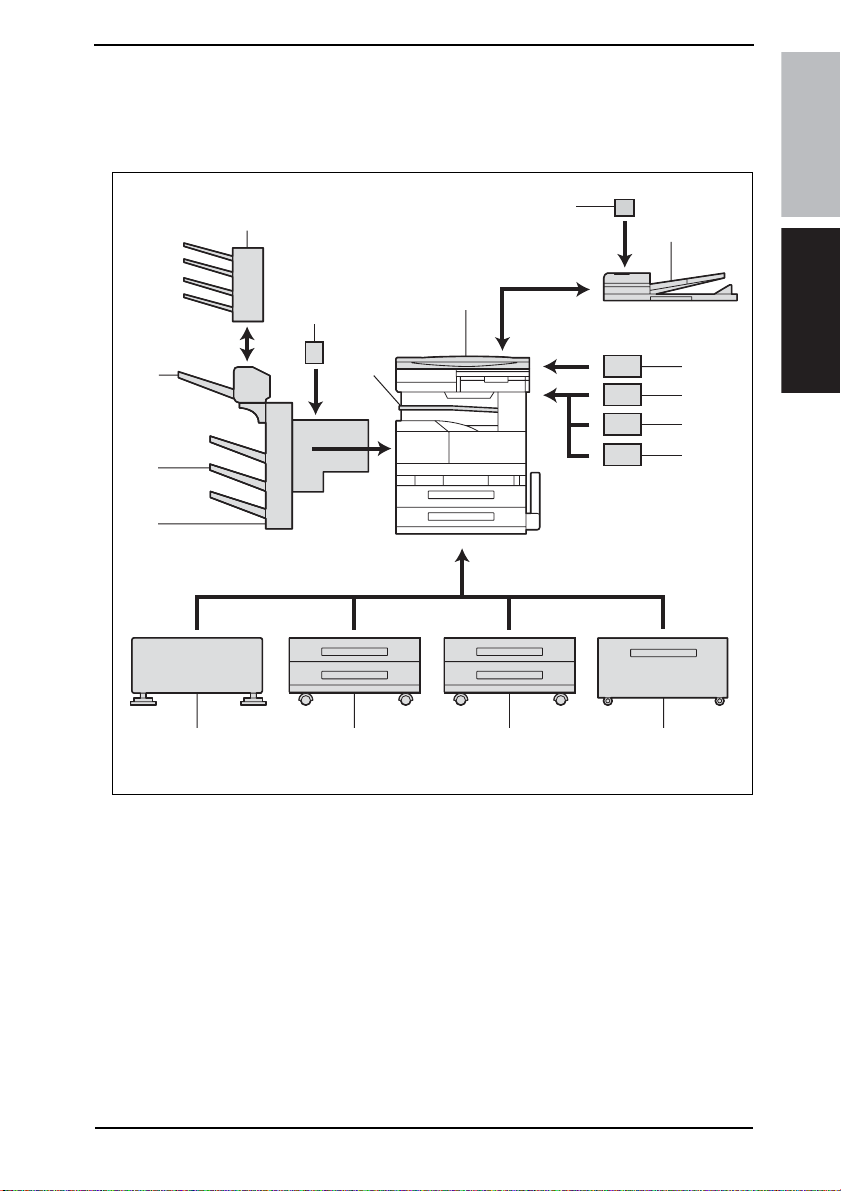
Field Service Ver. 1.0 Aug. 2005 1. System configuration
General
1. System configuration
1/2 System Front View
[14]
[13]
[12]
[11]
[17]
[16]
[10]
[15]
[1]
[9]
[2]
bizhub 200/250/350General
[3]
[4]
[5]
[6]
[7]
[8]
4040T1E501AA
[1] Original Cover (OC-502) [10] Paper Feed Cabinet (PC-101)
[2] Stamp Unit (SP-501) [11] Desk (DK-501)
Reverse Automatic Document Feeder
[3]
(DF-605)
[4] Data Controller (D-103) [13] Output T ray (OT-601)
[5] Key Counter Kit 4 [14] Saddle Sticher (SD-502)
[6] Key Counter *1 [15] Job Separator (JS-502)
[7] Key Counter Mount Kit *2 [16] Punch Unit (PU-501)
[8] Paper Feed Cabinet (PC-402) [17] Mailbin Kit (MT-501)
[9] Paper Feed Cabinet (PC-202)
[12] Finisher (FS-508)
*1:Key Counter Only
*2:Mount Pleate Only
1
Page 41
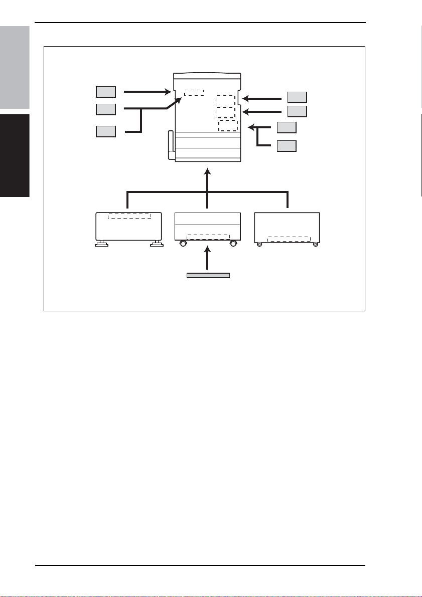
1. System configuration Field Service Ver. 1.0 Aug. 2005
2/2 System Rear View
bizhub 200/250/350
General
[9]
[8]
[7]
[1]
DK-501 PC-202 PC-402
[6]
[1] Machine [5] Dehumidifier Heater 1C
[2] Fax Kit (FK-503) [6] Scanner Unit (SU-501)*2
[3] Fax Multi Line (ML-502) [7]
[4] Local Interface kit (EK-502) [8] Hard Disk (HD-504)
Expanded Memory Unit
(EM-303/EM-304/EM-305)*2
*1:The Expanded Memory Unit and Scanner Unit cannot be mounted at the same time.
[2]
[3]
[4]
[5]
4040T1J504AA
2
Page 42

Field Service Ver. 1.0 Aug. 2005 2. Product specifications
2. Product specifications
A. Type
Type Desktop/Console (dedicated cabinet or dedicated table)
Copying System Electrostatic dry powdered image transfer to plain paper
PC Drum Type OPC (organic photo conductor)
Scanning Density Equivalent to 600 dpi
Exposure Lamp cold-cathode tube
Print Density Main scan: 600 dpi; sub-scan: 600 dpi
Platen Stationary (mirror scan)
Original Scanning Scanning in main scanning direction with a CCD
Registration Rear left edge
Paper Feeding System
(Standard)
Three-way system
Exposure System Electrostatic dry powdered image transfer to plain paper with a laser
Developing System HMT developing system
Charging System Comb electrode with scorotron system
Image Transfer System Image transfer roller system
Paper Separating System Separator fingers
Fusing System Heat roller
B. Functions
Types of Original Sheets, books, and three-dimensional objects
Max. Original Size A3 or 11 × 17
Multiple Copies 1 to 999
Warming-up Time
Image Loss
First Copy Time
(Tray1, A4, full size)
System Speed
Copying Speed for
Multi-copy Cycle
(A4, 8-1/2 × 11)
Fixed Zoom Ratios
Variable Zoom Ratios ×0.250 to ×4.000 in 0.001 increments
Multiple Bypass: 150 sheets
Tray1: 500 sheets
Tray2: 500 sheets
14 sec. or less
(when the Auxiliary Po wer Switch is turned ON from a stab iliz ed state , in whi ch
the Main Pow er Switch is ON an d A uxil iary P ow er Switch is OFF, with the rated
power source voltage and at a room temperature of 23°C)
Leading edge: 4 mm (1/4 inch), Trailing edge: 4 mm (1/4 inch),
Rear edge: 4 mm (1/4 inch), Front edge: 4 mm (1/4 inch)
4.8 sec. or less (bizhub 350)
5.3 sec. or less (bizhub 250)
5.3 sec. or less (bizhub 200)
160 m/s (bizhub 350)
140 m/s (bizhub 250, bizhub 200)
35 copies/min (bizhub 350)
25 copies/min (bizhub 250)
20 copies/min (bizhub 200)
Full size x1.000
Reduction
Enlargement
Metric Area: x0.500, x0.707, x0.816, x0.930
Inch Area: x0.500, x0.647, x0.733, x0.785, x0.930
Metric Area: x1.154, x1.414, x2.000
Inch Area: x1.214, x1.294, x1.545, x2.000
bizhub 200/250/350General
3
Page 43

2. Product specifications Field Service Ver. 1.0 Aug. 2005
C. Types of Paper
Paper Source
297 to 432 mm
11 × 17 inches
90 to 140 mm
3.5 x 5.5 inches
bizhub 200/250/350
Copy
paper type
General
Copy
paper
dimensions
Paper Source
Plain paper
(56 to 90 g/m
/ 15 to 24 lb)
Translucent paper - - OHP transparencies - - ❍
Thick paper (91 to 210 g/m
/ 24-1/4 to 55-3/4 lb)
Postcards - - ❍
Envelopes - - ❍
Labels - - ❍
Thin Paper (50 to 55 g/m
/ 13-1/4 to 14-3/4 lb)
Max. (width × length)
Min. (width × length)
2
2
2
Tray1 Tray2 Multiple Bypass
❍❍❍
--❍
--❍
297 to 420 mm
11.5 x 16.5 inches
148 to 210 mm
5.75 x 8.25 inches
❍: Reliably fed - : Feeding prohibited
D. Maintenance
Machine Durability
1200,000 prints or 5 years, whichever is earlier (bizhub 350)
800,000 prints or 5 years, whichever is earlier (bizhub 250)
500,000 prints or 5 years, whichever is earlier (bizhub 200)
E. Machine Specifications
Power Requirements
Max Power Consumption
Dimensions 677 (W) x 710 (D) x 718 (H) mm
Space Requirements 687 (W) x 710 (D) mm *1
Mass 74 kg (including the Duplex Unit, Switchback Unit, and Imaging Unit)
Voltage AC 120 V, 220 - 240 V
Frequency 50/60 Hz
120 V: 1380 W ± 10 %
200 V: 1300 - 1470 W ± 10 %
*1: Space requirements represent the dimensions of the machine when the Multi Bypass
Tray is lowered.
F. Operating Environmen
Temperature 10 to 32 °C / 50 to 89.6° F (with a fluctuation of 10° C / 18° F or less per hour)
Humidity 15 to 85 % (with a fluctuation of 20 %/h)
4
Page 44

Field Service Ver. 1.0 Aug. 2005 3. Built-in Controllers
3. Built-in Controllers
Type Built-in type controller
CPU RM5231
Printer Driver
Scan Driver TWAIN driver
OS Compatibility
Interface
NOTE
• These specifications are subject to change without notice.
PCL5e Emulation
PCL6 (XL Ver. 2.1)Emulation
PostScript3 Emulation (3011.xx.xx)
Server Windows NT4.0 sp6 / 2000 / 2003
Windows 98SE / Me
Client
Ethernet (10 Base-T/100 Base-TX)
USB 2.0/1.1
Windows 2000 / XP
Windows NT4.0 sp6
Linux (2nd-compliant)
Macintosh OS 9.2 or later / OS X 10.2 or later
bizhub 200/250/350General
5
Page 45

3. Built-in Controllers Field Service Ver. 1.0 Aug. 2005
bizhub 200/250/350
General
Blank Page
6
Page 46

Field Service Ver. 1.0 Aug. 2005 4. Periodical check
Maintenance
4. Periodical check
4.1 Service schedule
4.1.1 bizhub 350
Guarantee period (5-year or 1,200,000 prints)
Per cycle × print
number
100,000 ●●●●●● ● ●●9
150,000 ●●●●●● ● ● 8
300,000 ●●● ●4
Main
body
400,000 ●● ●3
450,000 ●● 2
900,000 ● 1
10 15 20 30 40 45 50 60 70 75 80 90 100 105 110 120
4.1.2 bizhub 250
Guarantee period (5-year or 800,000 prints)
Per cycle × print
number
80,000 ●●●●●●●●●●10
150,000 ●●●●●5
Main
300,000 ●●2
body
320,000 ●●2
450,000 ● 1
8 1516243032404548566064727580
×10,000-print
×10,000-print
Number
of times
Number
of times
bizhub 200/250/350Maintenance
4.1.3 bizhub 200
Guarantee period (5-year or 500,000 prints)
Per cycle × print
number
65,000 ●● ●● ●● ● 7
150,000 ●●●3
Main
260,000 ● 1
body
300,000 ● 1
450,000 ● 1
6.5 13 1519.526 3032.539 4545.5
×10,000-print
Number
of times
7
Page 47

4. Periodical check Field Service Ver. 1.0 Aug. 2005
4.1.4 Option
Guarantee period (5-year or 1,200,000 prints)
×10,000-print
bizhub 200/250/350
PC-102
PC-202
PC-402
DF-605
FS-508
MT-501
SD-502
Per cycle
× print
number
300,000 ●●●3
50,000 ●●●●●●●●●●●●●●●●●●● ● 20
200,000 ●●●● ●5
300,000 ●●●3
5101520253035404550556065707580859095100
4.2 Maintenance items
4.2.1 bizhub 350 A. Periodical parts replacement 1 (per 50,000-print)
Maintenance
No Class Parts to be replaced
Number of
personnel
1
Overall
2 Appearance ●●
3
4 Feed Roller 1 ●
5 Separation Roller 1 ●
DF-605
6 Rollers and rolls ●
7 Scanning Guide 1 ●
8 Reflective Sensor section 1 ●
Paper take-up and
image conditions
Pick-up Roller 2 ●
Check Clean Replace
●
Lubrication
Num
ber
of
times
Descrip-
tions
B. Periodical parts replacement 2 (per 100,000-print)
No Class Parts to be replaced
1
Overall
2 Appearance ●●
3
Processing
section
4 Toner Filter (Developing Unit) 1 ●
Paper take-up and
image conditions
Photo Conductor Unit 1 ●
Number of
personnel
Check Clean Replace
●
8
Lubri-
cation
Descrip-
tions
Page 48

Field Service Ver. 1.0 Aug. 2005 4. Periodical check
C. Periodical parts replacement 3 (per 150,000-print)
Lubri-
No Class Parts to be replaced
1
Overall
2 Appearance ●●
Transport
3
section
Image
4
Transfer
Section
Paper take-up and image
conditions
Paper Dust Remover 1 ●
Transfer Roller Unit 1 ●
Number of
personnel
Check Clean Replace
●
cation
Descrip-
tions
D. Periodical parts replacement 4 (per 200,000-print)
Lubri-
No Class Parts to be replaced
1
Overall
2 Appearance ●●
3
DF-605
4 Feed Roller 1 ●
5 Separation Roller 1 ●
Paper take-up and image
conditions
Pick-up Roller 2 ●
Number of
personnel
Check Clean Replace
●
cation
Descrip
tions
E. Periodical parts replacement 5 (per 300,000-print)
No Class Pa rts to be replaced
1
Overall
2 Appearance ●●
3
Bypass
4 Separation Roller Assy 1 ●
5
Tray 1
6 Pick-up Roller 1 ●
7 Separation Roller Assy 1 ●
8
Tray 2
9 Pick-up Roller 1 ●
10 Separation Roller Assy 1 ●
11
PC-102
PC-202
12 Feed Roller 1 ●
PC-402
13 Separation Roller Assy 1 ●
14 FS-508 Rollers and rolls ●
15 MT-501 Rollers and rolls ●
16 SD-502 Rollers and rolls ●
Paper take-up and
image conditions
Feed Roller 1 ●
Feed Roller 1 ●
Feed Roller 1 ●
Pick-up Roller 1 ●
Number of
personnel
Check Clean Replace
●
Lubrication
Descrip-
tions
bizhub 200/250/350Maintenance
9
Page 49

4. Periodical check Field Service Ver. 1.0 Aug. 2005
F. Periodical parts replacement 6 (per 400,000-print)
No Class Parts to be replaced
1
Overall
bizhub 200/250/350
2 Appearance ●●
3
Processing
section
4 Toner Filter (Main Unit) 1 ●
Number of
personnel
Paper take-up and
image conditions
Developing Unit 1 ●
Check Clean Replace
●
Lubrication
G. Periodical parts replacement 7 (per 450,000-print)
No Class Parts to be replaced
1
Overall
2 Appearance ●●
Fusing
3
section
Paper take-up and
image conditions
Fusing Unit 1 ●
Number of
personnel
Check Clean Replace
●
Lubrication
H. Periodical parts replacement 8 (per 900,000-print)
Maintenance
No Class Parts to be replaced
Number of
personnel
1
Overall
2 Appearance ●●
3
Transpor t
section
4 Registration Roller Gear ●
Paper take-up and
image conditions
Registration Roller Bearing ●
Check Clean Replace
●
Lubrication
Descrip-
tions
Descrip-
tions
Descrip-
tions
4.2.2 bizhub 250 A. Periodical parts replacement 1 (per 50,000-print)
No Class Parts to be replaced
1
Overall
2 Appearance ●●
3
4 Feed Roller 1 ●
5 Separation Roller 1 ●
DF-605
6 Rollers and rolls ●
7 Scanning Guide 1 ●
8 Reflective Sensor section 1 ●
Paper take-up and
image conditions
Pick-up Roller 2 ●
Number of
personnel
Check Clean Replace
●
10
Lubrication
Descrip-
tions
Page 50

Field Service Ver. 1.0 Aug. 2005 4. Periodical check
B. Periodical parts replacement 2 (per 80,000-print)
Lubri-
No Class Parts to be replaced
1
Overall
2 Appearance ●●
3
Processing
section
4 Toner Filter (Developing Unit) 1 ●
Paper take-up and
image conditions
Photo Conductor Unit 1 ●
Number of
personnel
Check Clean Replace
●
cation
Descrip-
tions
C. Periodical parts replacement 3 (per 150,000-print)
Lubri-
No Class Parts to be replaced
1
Overall
2 Appearance ●●
Transport
3
section
Image
4
Transfer
Section
Paper take-up and image
conditions
Paper Dust Remover 1 ●
Transfer Roller Unit 1 ●
Number of
personnel
Check Clean Replace
●
cation
Descrip-
tions
D. Periodical parts replacement 4 (per 200,000-print)
Lubri-
No Class Parts to be replaced
1
Overall
2 Appearance ●●
3
DF-605
4 Feed Roller 1 ●
5 Separation Roller 1 ●
Paper take-up and image
conditions
Pick-up Roller 2 ●
Number of
personnel
Check Clean Replace
●
cation
Descrip
tions
bizhub 200/250/350Maintenance
11
Page 51

4. Periodical check Field Service Ver. 1.0 Aug. 2005
E. Periodical parts replacement 5 (per 300,000-print)
No Class Parts to be replaced
1
Overall
bizhub 200/250/350
Maintenance
2 Appearance ●●
3
Bypass
4 Separation Roller Assy 1 ●
5
Tray 1
6 Pick-up Roller 1 ●
7 Separation Roller Assy 1 ●
8
Tray 2
9 Pick-up Roller 1 ●
10 Separation Roller Assy 1 ●
11
PC-102
PC-202
12 Feed Roller 1 ●
PC-402
13 Separation Roller Assy 1 ●
14 FS-508 Rollers and rolls ●
15 MT-501 Rollers and rolls ●
16 SD-502 Rollers and rolls ●
Number of
personnel
Paper take-up and
image conditions
Feed Roller 1 ●
Feed Roller 1 ●
Feed Roller 1 ●
Pick-up Roller 1 ●
Check Clean Replace
●
Lubri-
cation
F. Periodical parts replacement 6 (per 320,000-print)
No Class Parts to be replaced
1
Overall
2 Appearance ●●
3
Processing
section
4 Toner Filter (Main Unit) 1 ●
Paper take-up and
image conditions
Developing Unit 1 ●
Number of
personnel
Check Clean Replace
●
Lubrication
Descrip-
tions
Descrip-
tions
G. Periodical parts replacement 7 (per 450,000-print)
No Class Parts to be replaced
1
Overall
2 Appearance ●●
Fusing
3
section
Paper take-up and
image conditions
Fusing Unit 1 ●
Number of
personnel
Check Clean Replace
●
12
Lubrication
Descrip-
tions
Page 52

Field Service Ver. 1.0 Aug. 2005 4. Periodical check
4.2.3 bizhub 200 A. Periodical parts replacement 1 (per 50,000-print)
Lubri-
No Class Parts to be replaced
1
Overall
2 Appearance ●●
3
4 Feed Roller 1 ●
5 Separation Roller 1 ●
DF-605
6 Rollers and rolls ●
7 Scanning Guide 1 ●
8 Reflective Sensor section 1 ●
Paper take-up and
image conditions
Pick-up Roller 2 ●
Number of
personnel
Check Clean Replace
●
cation
Descrip-
tions
B. Periodical parts replacement 2 (per 65,000-print)
No Class Parts to be replaced
1
Overall
2 Appearance ●●
3
Processing
section
4 Toner Filter (Developing Unit) 1 ●
Paper take-up and
image conditions
Photo Conductor Unit 1 ●
Number of
personnel
Check Clean Replace
●
Lubri-
cation
Descrip-
tions
C. Periodical parts replacement 3 (per 150,000-print)
No Class Parts to be replaced
1
Overall
2 Appearance ●●
Transport
3
section
Image
4
Transfer
Section
Paper take-up and image
conditions
Paper Dust Remover 1 ●
Transfer Roller Unit 1 ●
Number of
personnel
Check Clean Replace
●
Lubri-
cation
Descrip-
tions
bizhub 200/250/350Maintenance
D. Periodical parts replacement 4 (per 200,000-print)
No Class Parts to be replaced
1
Overall
2 Appearance ●●
3
DF-605
4 Feed Roller 1 ●
5 Separation Roller 1 ●
Paper take-up and image
conditions
Pick-up Roller 2 ●
Number of
personnel
Check Clean Replace
●
Lubri-
cation
Descrip
tions
13
Page 53

4. Periodical check Field Service Ver. 1.0 Aug. 2005
E. Periodical parts replacement 5 (per 260,000-print)
No Class Parts to be replaced
1
Overall
bizhub 200/250/350
2 Appearance ●●
3
Processing
section
4 Toner Filter (Main Unit) 1 ●
Number of
personnel
Paper take-up and
image conditions
Developing Unit 1 ●
Check Clean Replace
●
Lubrication
F. Periodical parts replacement 6 (per 300,000-print)
No Class Parts to be replaced
Maintenance
10 Separation Roller Assy 1 ●
11
12 Feed Roller 1 ●
13 Separation Roller Assy 1 ●
14 FS-508 Rollers and rolls ●
15 MT-501 Rollers and rolls ●
16 SD-502 Rollers and rolls ●
Number of
personnel
1
Overall
2 Appearance ●●
3
Bypass
4 Separation Roller Assy 1 ●
5
Tray 1
6 Pick-up Roller 1 ●
7 Separation Roller Assy 1 ●
8
Tray 2
9 Pick-up Roller 1 ●
PC-102
PC-202
PC-402
Paper take-up and
image conditions
Feed Roller 1 ●
Feed Roller 1 ●
Feed Roller 1 ●
Pick-up Roller 1 ●
Check Clean Replace
●
Lubri-
cation
Descrip-
tions
Descrip-
tions
G. Periodical parts replacement 7 (per 450,000-print)
No Class Parts to be replaced
1
Overall
2 Appearance ●●
Fusing
3
section
Paper take-up and
image conditions
Fusing Unit 1 ●
Number of
personnel
Check Clean Replace
●
14
Lubrication
Descrip-
tions
Page 54

Field Service Ver. 1.0 Aug. 2005 4. Periodical check
4.3 Maintenance parts
• To ensure that the machine produces good copies and to extend its service life, it is recommended that the maintenance jobs described in this schedule be carried out as
instructed.
• Replace with reference to the numeric values displayed on the Life counter.
• The conditions are: A4 or 8-1/ 2x11, standard mode, and no Sleep.
4.3.1 Replacement parts
A. Main unit
Actual
Qua
No Classification Parts name
1
Bypass
2 Separation Roller Assy 1 300 K 4034-0151-XX
3
4 Pick-up Roller 1 300 K 4030-3005-XX
Tray 1
5 Separation Roller Assy 1 300 K 4030-0151-XX
6
7 Pick-up Roller 1 300 K 4030-3005-XX
Tray 2
8 Separation Roller Assy 1 300 K 4030-0151-XX
9
10 Registration Roller Gear 1 1 900 K 1164-3508-XX
Transport
section
11 Paper Dust Remover 1 150 K 4040-0778-XX
Fusing
12
section
Transfer
13
section
14
15 bizhub 250 1 80 K
16 bizhub 200 1 65 K
17
18 bizhub 250 1 80 K
19 bizhub 200 1 65 K
Processing
section
20
21 bizhub 250 1 320 K 4040-0752-XX
22 bizhub 200 1 260 K 4040-0752-XX
23
24 bizhub 250 1 80 K 4040-5217-XX
25 bizhub 200 1 65 K 4040-5217-XX
Feed Roller 1 300 K 4131-3001-XX
Feed Roller 1 300 K 4030-3005-XX Replace
Feed Roller 1 300 K 4030-3005-XX Replace
Registration Roller Bearing 4 900 K 1164-3549-XX
Registration Roller Gear 2 1 900 K 1164-3515-XX
Fusing Unit 1 450 K
Transfer Roller Unit 1 150 K 4040-0760-XX
Photo
Conductor
Unit
Developer
Developing
Unit
Toner Filter
(Developing
Unit)
bizhub 350 1 100 K
bizhub 350 1 100 K
bizhub 350 1 400 K 4040-0752-XX
bizhub 350 1 100 K 4040-5217-XX
ntity
durable
cycle *1
Parts No. Descriptions
4040-0765-XX
4040-0766-XX
4040-0767-XX
-*2
-
those three
parts at the
same time.
those three
parts at the
same time.
120 V/127 V
areas only.
220 - 240 V
areas only.
110 V areas
only.
*3
*2
Ref.Page
in this
manual
☞ 18
☞ 19
☞ 20
☞ 21
☞ 23
☞ 25
☞ 26
☞ 28
☞ 30
☞ 30
☞ 30
☞ 31
☞ 37
☞ 38
☞ 39
☞ 34
☞ 40
☞ 32
bizhub 200/250/350Maintenance
15
Page 55

4. Periodical check Field Service Ver. 1.0 Aug. 2005
No Classification Parts name
26
Processing
27 bizhub 250 1 320 K 4040-2093-XX
section
bizhub 200/250/350
28 bizhub 200 1 260 K 4040-2093-XX
29 Ozone Filter 1 300 K 4011-2031-XX
Toner Filter
(Main Unit)
durable
ntity
cycle *1
bizhub 350 1 400 K 4040-2093-XX
Parts No. Descriptions
*3
Actual
Qua
*1: Actual durable cycle is the Special Parts Counter value.
*2: The Photo Conductor Unit and Toner Filter (Developing Unit) should be replaced with
new ones at the same time.
*3: The Developing Unit and Toner Filter (Main Unit) should be replaced with new ones at
the same time.
B. Option
No Classification Parts name
Maintenance
durable
ntity
cycle *1
1
PC-102
PC-202
2 Feed Roller 1 300 K 4030-3005-XX
PC-402
3 Separation Roller Assy 1 300 K 4030-0151-XX
4
DF-605
5 Feed Roller 1 200 K 4582-3014-XX
6 Separation Roller 1 200 K 4582-3047-XX
7 SP-501
Pick-up Roller 1 300 K 4030-3005-XX
Pick-up Roller 1 200 K 4344-5003-XX
Spare TX Marker
Stamp 2
1
As
required
Parts No. Descriptions
Replace those
three parts at the
same time.
Replace those
three parts at the
same time.
- Ink running out
Actual
Qua
*1: Actual durable cycle is the Special Parts Counter value.
*2: See each Option Service Manual.
Ref.Page
in this
manual
☞ 33
☞ 33
Ref.Page
in this
manual
*2
4.3.2 Cleaning parts
No Classification Parts name Actual durable cycle *1 Descriptions
1
2 Feed Roller 50 K
3 Separation Roller 50 K
DF-605
4 Misc. rollers and rolls 50 K
5 Scanning Guide 50 K
6 Reflective Sensor section 50 K
7 FS-508 Rollers and rolls 300 K *3
8 MT-501 Rollers and rolls 300 K *4
9 SD-502 Rollers and rolls 300 K *5
Pick-up Roller 50 K
*1: Actual durable cycle is the Special Parts Counter value.
*2: See DF-605 Service manual.
*3: See FS-508 Service manual.
*4: See MT-501 Service manual.
*5: See SD-502 Service manual.
16
Ref.Page
in this
manual
*2
Page 56

Field Service Ver. 1.0 Aug. 2005 4. Periodical check
4.4 Concept of parts life
Description
Photo Conductor Unit
Developer
Developing Unit Photo Conductor Unit × 4 times
Fusing Unit Count the number of times paper is fed out.
The distance through which the Photo Conductor has been rotated is converted to a corresponding number of printed pages produced
on A4 paper at 4P/J and the life condition is
detected when a predetermined value is
reached.
Life value
(Specification
value)
*1
100
*1
100
*1
400
*1
450
Lift stop
Not stopped
*2
Not stopped
*2
Not stopped
*1: On the bizhub 350
*2: The setting can be changed to “stopped” by using the soft switch of the Tech. Rep.
mode.
A. Conditions for Life Specifications Values
• The life specification values represent the number of copies made or figures equivalent to it when
given conditions (see the Table given below) are met. They can be more or less depending on the
machine operating conditions of each individual user.
Item Description
bizhub 350 bizhub 250 bizhub 200
Job Type 4 page/Job 3 page/Job 2 page/Job
Paper Size A4
Original Density B/W ratio: 6 %
Average Copy Volume
(copies/month)
7,000 4,000 2,500
bizhub 200/250/350Maintenance
17
Page 57
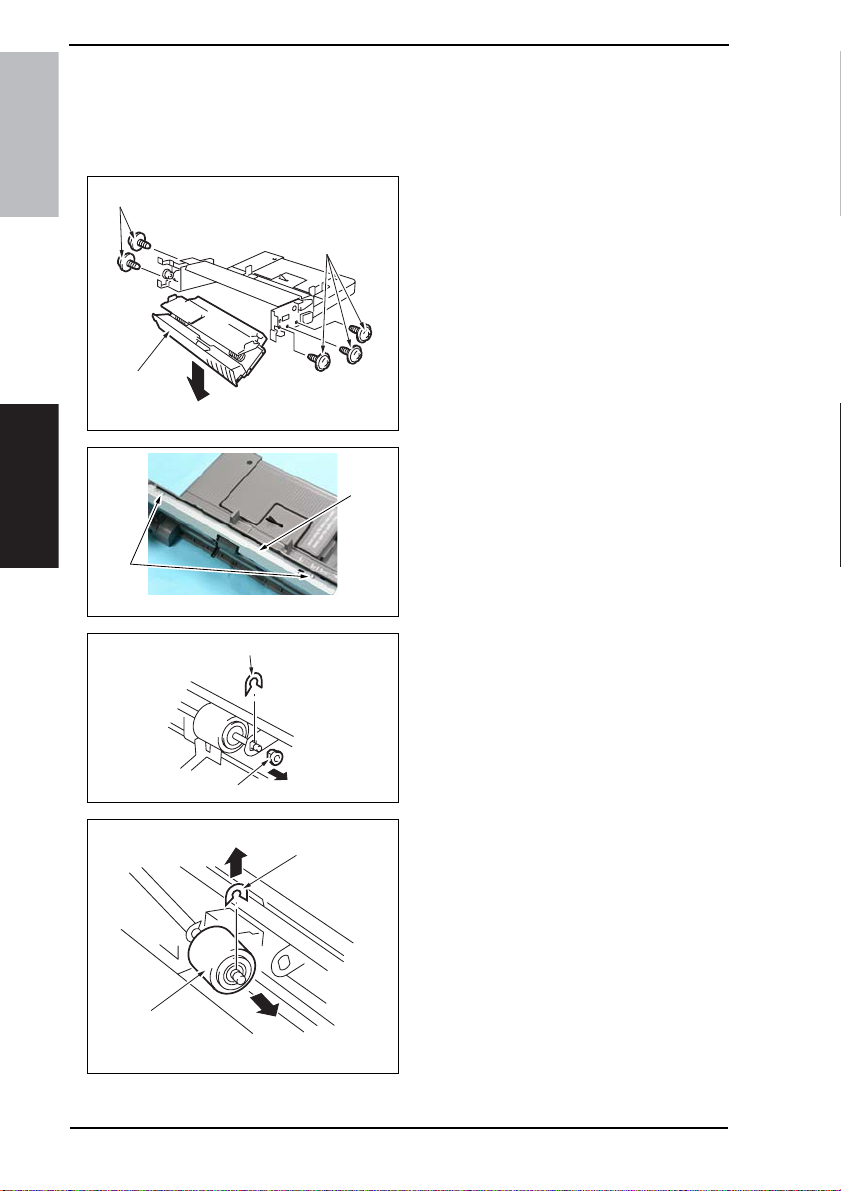
4. Periodical check Field Service Ver. 1.0 Aug. 2005
4.5 Maintenance procedure (Periodical check parts)
4.5.1 Replacing the Bypass Tray Feed Roller
1. Remove the Multi Bypass Unit.
☞ 71
bizhub 200/250/350
Maintenance
[1]
[2]
[3]
[1]
4037F2C518DA
[4]
4040F2C708DA
2. Remove five screws [1] and the Manual Bypass Unit Lower Frame [2].
3. Remove two screws [3] and the Feed
Roller Cover [4].
18
[8]
[6]
[5]
4040F2C506DA
[7]
4037F2C520DA
4. Snap off the C-clip [5] for the Feed
Roller, and remove the bearing. [6].
5. Snap off the C-clip [7], and remove
the Bypass Feed Roller [8].
6. To reinstall, reverse the order of
removal.
7. Select [Tech. Rep. Mode] →
[Counter] → [Special Parts Counter]
→ [Bypass] and clear the counter.
NOTE
• Replace the Bypass Feed Roller
and the Bypass Separation Roller
Assy at the same time.
Page 58

Field Service Ver. 1.0 Aug. 2005 4. Periodical check
4.5.2 Replacing the Bypass Tray Separation Roller Assy
1. Remove the Multi Bypass Unit.
☞ 71
[1]
[2]
2. Remove two screws [1], and remove
Bypass Paper Separation Roller fixing bracket Assy [2].
4037F2C515DA
bizhub 200/250/350Maintenance
[3]
[5]
[6]
[4]
4037F2C522DA
3. Snap off the C-clip [3], and remove
the spring [4] and the guide plate [5].
Remove the Bypass Paper Separation Roller Assy [6].
4. To reinstall, reverse the order of
removal.
5. Select [Tech. Rep. Mode] →
[Counter] → [Special Parts Counter]
→ [Bypass] and clear the counter.
NOTE
• Replace the Bypass Feed Roller
and the Bypass Separation Roller
Assy at the same time.
19
Page 59

4. Periodical check Field Service Ver. 1.0 Aug. 2005
4.5.3 Replacing the Tray 1 Feed Roller
[2]
bizhub 200/250/350
1. Remove the screw [1] and, holding
the stopper [2], remove Tray 1 [3].
Maintenance
[5]
[3]
[11]
[7]
[4]
[6]
[1]
4040F2C508DA
4040F2C509DA
[8]
4040F2C510DA
[10]
2. Remove two screws [4] and the Connector Cover [5].
3. Remove the Connector [6].
4. Remove two screws [7] and the Tray
1 Feed Roller Assy [8].
5. Remove four screws [9] and the Tray
1 Feed Roller Assy Cover [10] and
the Tray 1 Separator Roll Assy [11].
20
[9]
[9]
4040F2C512DA
Page 60

Field Service Ver. 1.0 Aug. 2005 4. Periodical check
[12]
[13]
[14]
[17]
[18]
[20]
4040F2C513DA
[15]
[16]
4040F2C514DA
[19]
4040F2C515DA
4.5.4 Replacing the Tray 1 Pick-up Roller
[2]
6. Remove the C-clip [12] and the bearing [13].
bizhub 200/250/350Maintenance
7. Remove the C-clip [14], E-ring [15],
bearing [16] and spring [17] to
remove the Tray 1 Feed Roller Assy
[18].
8. Remove the C-clip [19] and the Tray
1 Feed Roller [20].
9. To reinstall, reverse the order of
removal.
10. Select [Tech. Rep. Mode] →
[Counter] → [Special Parts Counter]
→ [Tray 1] and clear the counter.
1. Remove the screw [1] and, holding
the stopper [2], remove Tray 1 [3].
[5]
[3]
[4]
[1]
4040F2C508DA
2. Remove two screws [4] and the Connector Cover [5].
4040F2C509DA
21
Page 61

4. Periodical check Field Service Ver. 1.0 Aug. 2005
3. Remove the Connector [6].
[6]
bizhub 200/250/350
[8]
[7]
4040F2C510DA
4. Remove two screws [7] and the Tray
1 Feed Roller Assy [8].
Maintenance
[13]
[9]
[11]
[16]
[14]
[10]
[9]
4040F2C512DA
[12]
[13]
4040F2C517DA
[15]
4040F2C518DA
5. Remove four screws [9] and the Tray
1 Feed Roller Assy Cover [10] and
the Tray 1 Separator Roll Assy [11].
6. Remove two C-clips [12] and two
bearings [13]. Then, remove the
Pick-up Roller Assy [14].
7. Remove one C-clip [15] and the Tray
1 Pick-up Roller [16].
8. To reinstall, reverse the order of
removal.
9. Select [Tech. Rep. Mode] →
[Counter] → [Special Parts Counter]
→ [Tray 1] and clear the counter.
22
Page 62

Field Service Ver. 1.0 Aug. 2005 4. Periodical check
4.5.5 Replacing the Tray 1 Separation Roller Assy
[2]
1. Remove the screw [1] and, holding
the stopper [2], remove Tray 1 [3].
bizhub 200/250/350Maintenance
[5]
[3]
[11]
[7]
[4]
[6]
[1]
4040F2C508DA
4040F2C509DA
[8]
4040F2C510DA
[10]
2. Remove two screws [4] and the Connector Cover [5].
3. Remove the Connector [6].
4. Remove two screws [7] and the Tray
1 Feed Roller Assy [8].
5. Remove four screws [9] and the Tray
1 Feed Roller Assy Cover [10] and
the Tray 1 Separator Roll Assy [11].
[9]
[9]
4040F2C512DA
23
Page 63

4. Periodical check Field Service Ver. 1.0 Aug. 2005
6. Remove two Screws [12] and the
Tray 1 Separation Roller installation
plate Assy [13].
bizhub 200/250/350
Maintenance
[12]
[14]
[17]
[18]
[13]
4040F2C520DA
[15]
[14]
4040F2C521DA
[16]
4040F2C522DA
4040F2C523DA
7. Remove two C-clips [14] and the
Tray 1 Separation Roller installation
plate [15].
8. Remove the C-clip [16] and the Tray
1 Separation Roller Assy [17].
9. To reinstall, reverse the order of
removal.
10. Select [Tech. Rep. Mode] →
[Counter] → [Special Parts Counter]
→ [Tray 1] and clear the counter.
NOTE
• Install the Tray 1 Separation Roller
Mounting Bracket Assy [18] while
pressing the holder up so that it
coheres to the metal bracket of the
copier.
24
Page 64
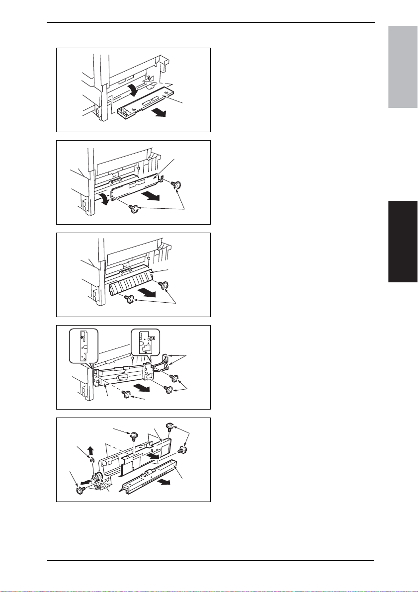
Field Service Ver. 1.0 Aug. 2005 4. Periodical check
4.5.6 Replacing the Tray 2 Feed Roller
1. Slide out the Tray 2.
2. Remove the Multi Bypass Unit.
☞ 71
3. Remove the Lower Right Cover [1].
[1]
4040F2C524DA
bizhub 200/250/350Maintenance
[10]
[9]
[8]
[9]
[13]
[7]
[11]
[3]
[2]
4040F2C526DA
[5]
[4]
4040F2C527DA
[6]
[7]
4040F2C591DA
[9]
[12]
4040F2C528DA
4. Remove two screws [2] and the
Transport Roller Cover [3].
5. Remove two screws [2] and the Misfeed Clearing Cover [5].
6. Unplug two connectors [6].
7. Remove three screws [7] and the
Tray 2 Feed Roller Assy [8].
8. Remove four screws [9] and the Cclip [10]. Then, remove the Tray 2
Feed Roller Cover [11], the Tray 2
Separation Roller Assy [12], and the
Tray 2 Feed Roller Clutch [13].
25
Page 65
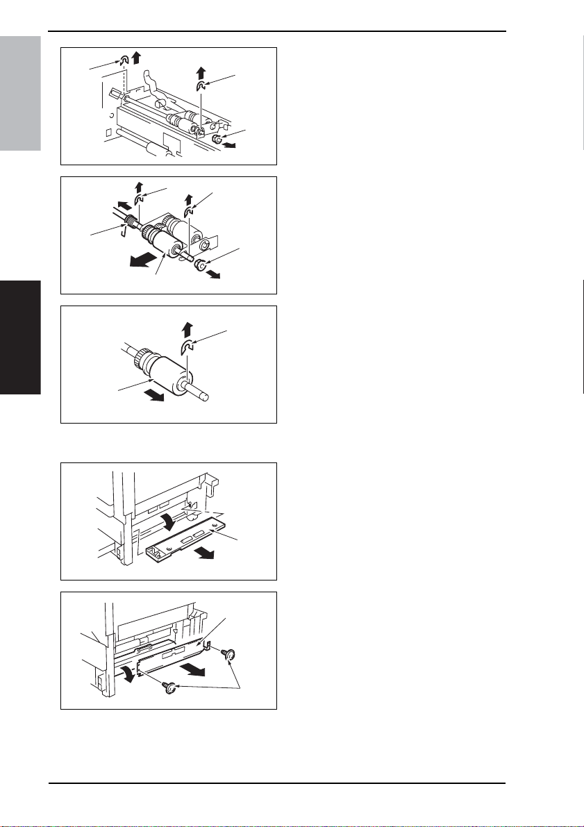
4. Periodical check Field Service Ver. 1.0 Aug. 2005
9. Remove two C-clips [14] and the
[14]
[14]
bearing [15].
bizhub 200/250/350
[16]
[19]
[20]
Maintenance
[22]
4.5.7 Replacing the Tray 2 Pick-up Roller
[15]
4040F2C529DA
[17]
[18]
4040F2C530DA
[21]
4040F2C531DA
10. Remove the C-clip [16], E-ring [17],
bearing [18] and spring [19] to
remove the Tray 2 Feed Roller Assy
[20].
11. Remove the C-clip [21] and the Tray
2 Feed Roller [22].
12. To reinstall, reverse the order of
removal.
13. Select [Tech. Rep. Mode] →
[Counter] → [Special Parts Counter]
→ [Tray 2] and clear the counter.
1. Slide out the Tray 2.
2. Remove the Multi Bypass Unit.
☞ 71
3. Remove the Lower Right Cover [1].
26
[1]
4040F2C524DA
[3]
[2]
4040F2C526DA
4. Remove two screws [2] and the
Transport Roller Cover [3].
Page 66
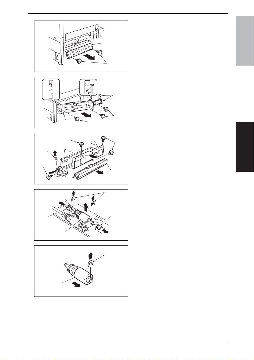
Field Service Ver. 1.0 Aug. 2005 4. Periodical check
5. Remove two screws [2] and the Misfeed Clearing Cover [5].
[5]
[10]
[9]
[15]
[16]
[8]
[9]
[13]
[7]
[11]
[4]
4040F2C527DA
[6]
[7]
4040F2C591DA
[9]
[12]
4040F2C528DA
[14]
[15]
4040F2C533DA
bizhub 200/250/350Maintenance
6. Unplug two connectors [6].
7. Remove three screws [7] and the
Tray 2 Feed Roller Assy [8].
8. Remove four screws [9] and the Cclip [10]. Then, remove the Tray 2
Feed Roller Cover [11], the Tray 2
Separation Roller Assy [12], and the
Tray 2 Feed Roller Clutch [13].
9. Remove two C-clips [14] and two
bearings [15]. Then, remove the Tray
2 Pick-up Roller Assy [16].
[18]
[17]
4040F2C534DA
10. Remove the C-clip [17] and the Tray
2 Pick-up Roller [18].
11. To reinstall, reverse the order of
removal.
12. Select [Tech. Rep. Mode] →
[Counter] → [Special Parts Counter]
→ [Tray 2] and clear the counter.
27
Page 67
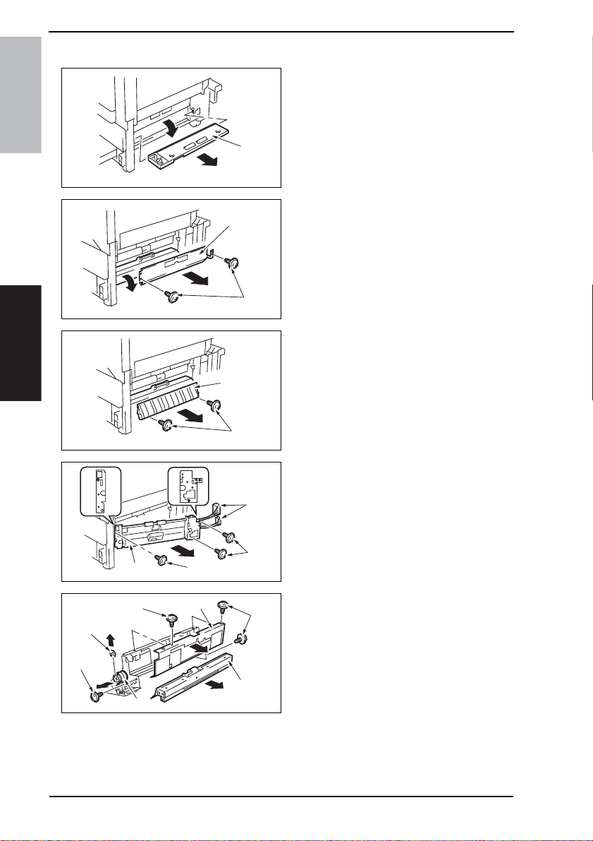
4. Periodical check Field Service Ver. 1.0 Aug. 2005
4.5.8 Replacing the Tray 2 Separation Roller
1. Slide out the Tray 2.
2. Remove the Multi Bypass Unit.
☞ 71
3. Remove the Lower Right Cover [1].
bizhub 200/250/350
[1]
4040F2C524DA
Maintenance
[10]
[9]
[8]
[9]
[13]
[7]
[11]
[3]
[2]
4040F2C526DA
[5]
[4]
4040F2C527DA
[6]
[7]
4040F2C591DA
[9]
[12]
4040F2C528DA
4. Remove two screws [2] and the
Transport Roller Cover [3].
5. Remove two screws [2] and the Misfeed Clearing Cover [5].
6. Unplug two connectors [6].
7. Remove three screws [7] and the
Tray 2 Feed Roller Assy [8].
8. Remove four screws [9] and the Cclip [10]. Then, remove the Tray 2
Feed Roller Cover [11], the Tray 2
Separation Roller Assy [12], and the
Tray 2 Feed Roller Clutch [13].
28
Page 68
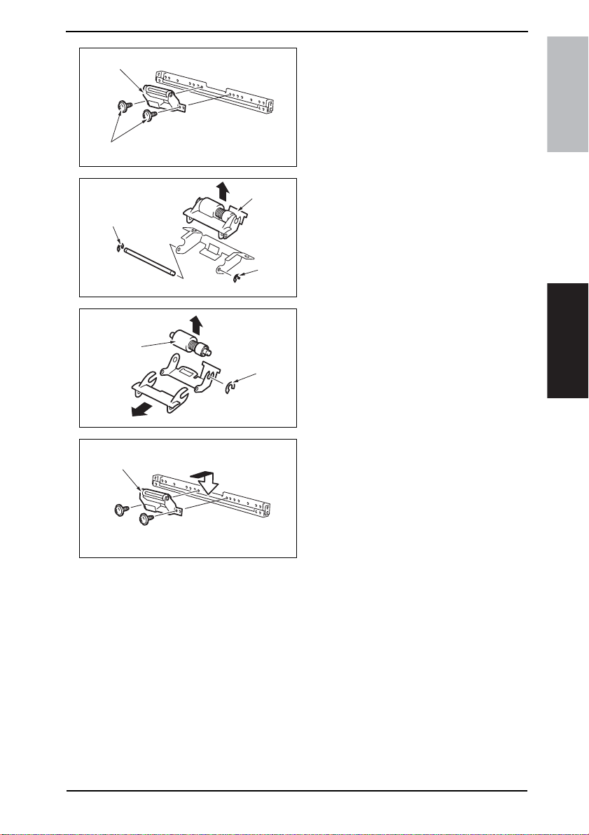
Field Service Ver. 1.0 Aug. 2005 4. Periodical check
[15]
[14]
[16]
[20]
[19]
4040F2C536DA
[17]
[16]
4040F2C537DA
[18]
4040F2C538DA
9. Remove two Screws [14] and the
Tray 2 Separation Roller installation
plate Assy [15].
bizhub 200/250/350Maintenance
10. Remove two C-clips [16] and the
Tray 2 Separation Roller installation
plate [17].
11. Remove the C-clip [18] and the Tray
2 Separation Roller Assy [19].
12. To reinstall, reverse the order of
removal.
13. Select [Tech. Rep. Mode] →
[Counter] → [Special Parts Counter]
→ [Tray 2] and clear the counter.
NOTE
• Install the Tray 2 Separation Roller
Mounting Bracket Assy [20] while
pressing the holder up so that it
coheres to the metal bracket of the
copier.
4040F2C539DA
29
Page 69
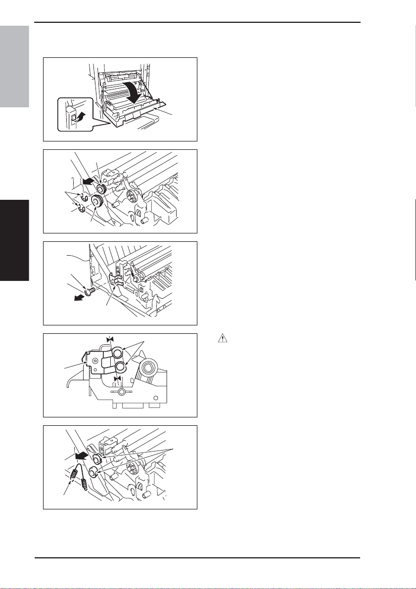
4. Periodical check Field Service Ver. 1.0 Aug. 2005
4.5.9 Replacing of the Registration Roller Bearings and Registration Roller Gears 1, 2
1. Open the Right Door [1].
bizhub 200/250/350
[1]
4040F2C540DA
[4]
2. Remove two E-rings [2], Registration
Roller Gears 1 [3] and Registration
Roller Gears 2 [4].
[2]
[3]
4040F2C544DA
3. Remove the screw [5] and the
Maintenance
[5]
[6]
4040F2C545DA
ground plate [6].
30
[7]
[9]
[8]
4040F2C546DA
4040F2C547DA
[10]
CAUTION
• When reinstalling the ground plate,
make sure that the ground plate [7]
is in contact with the side faces of
the bushings [8].
4. Remove the spring [9] and two Registration Roller Bearings [10].
NOTE
• When reinstalling the bearings,
make sure that the flanges of the
bearings are on the outside.
Page 70
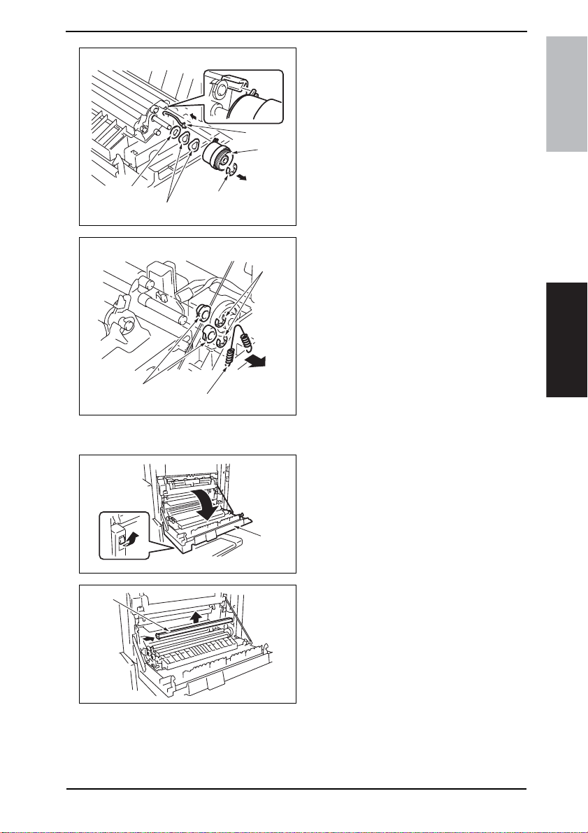
Field Service Ver. 1.0 Aug. 2005 4. Periodical check
5. Remove the E-ring [11] and unplug
the connector [12]. Then, remove the
Registration Roller Clutch [13].
6. Remove the washer [14] and two
wave washers [15].
[12]
[13]
bizhub 200/250/350Maintenance
[14]
[15]
[18]
[16]
[11]
4040F2C548DA
[17]
4040F2C549DA
4.5.10 Cleaning of the Paper Dust Remover
[1]
4040F2C540DA
[2]
7. Remove the spring [16], two E-rings
[17], and two Registration Roller
Bearings [18].
NOTE
• When reinstalling the bearings,
make sure that the flanges of the
bearings are on the outside.
1. Open the Right Door [1].
2. Remove the Paper Dust Removal [2].
4040F2C541DA
31
Page 71
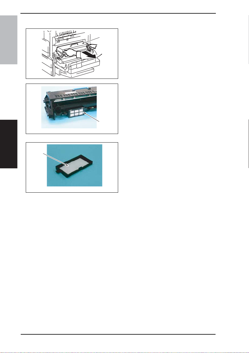
4. Periodical check Field Service Ver. 1.0 Aug. 2005
4.5.11 Replacing of the Toner Filter (Developing Unit)
1. Open the Right Door.
[1]
bizhub 200/250/350
4040F2C555DA
2. Remove the IU [1].
3. Remove the Toner Filter Cover [2].
[2]
4040F2C655DA
4. Remove the Toner Filter (Develop-
Maintenance
[3]
ing Unit) [3].
NOTE
• Replace the Photo Conductor Unit
with a new one at the same time.
32
4040F2C654DA
Page 72
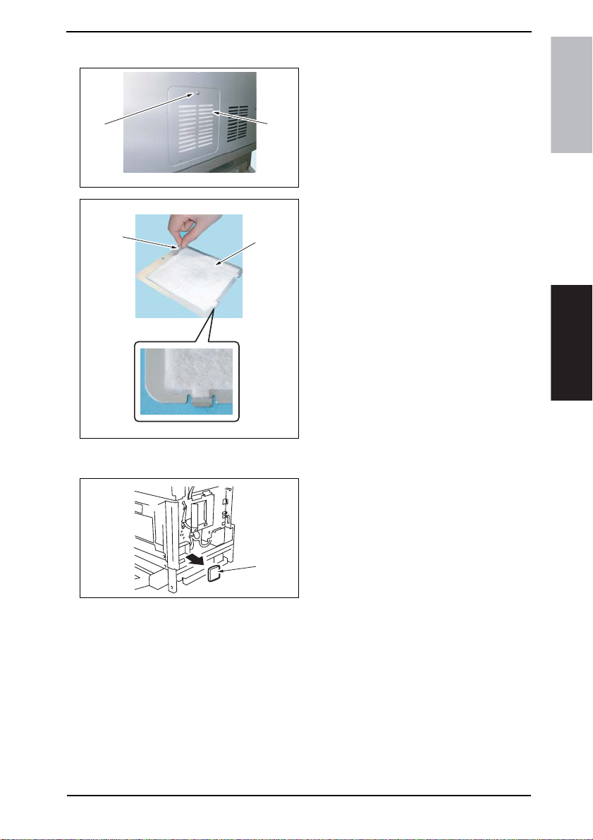
Field Service Ver. 1.0 Aug. 2005 4. Periodical check
4.5.12 Replacing of the Toner Filter (Main Unit)
1. Remove the screw [1] and the Toner
Filter Rear Cover [2].
[1]
[3]
[2]
4040F2C558DA
[4]
4040F2C557DA
4.5.13 Replacement of the Ozone Filter
[1]
bizhub 200/250/350Maintenance
2. Pull on the tape portion [3] and peel
off the Toner Filter (Main Unit) [4].
NOTE
• When mounting the filter, not the
correct mounting position that is
shown on the left.
• Replace the Developing Unit with a
new one at the same time.
1. Remove the Upper Rear Cover.
☞ 50
2. Remove the Rear Cover.
☞ 51
3. Remove the Ozone Filter [1].
4040F2C559DA
33
Page 73
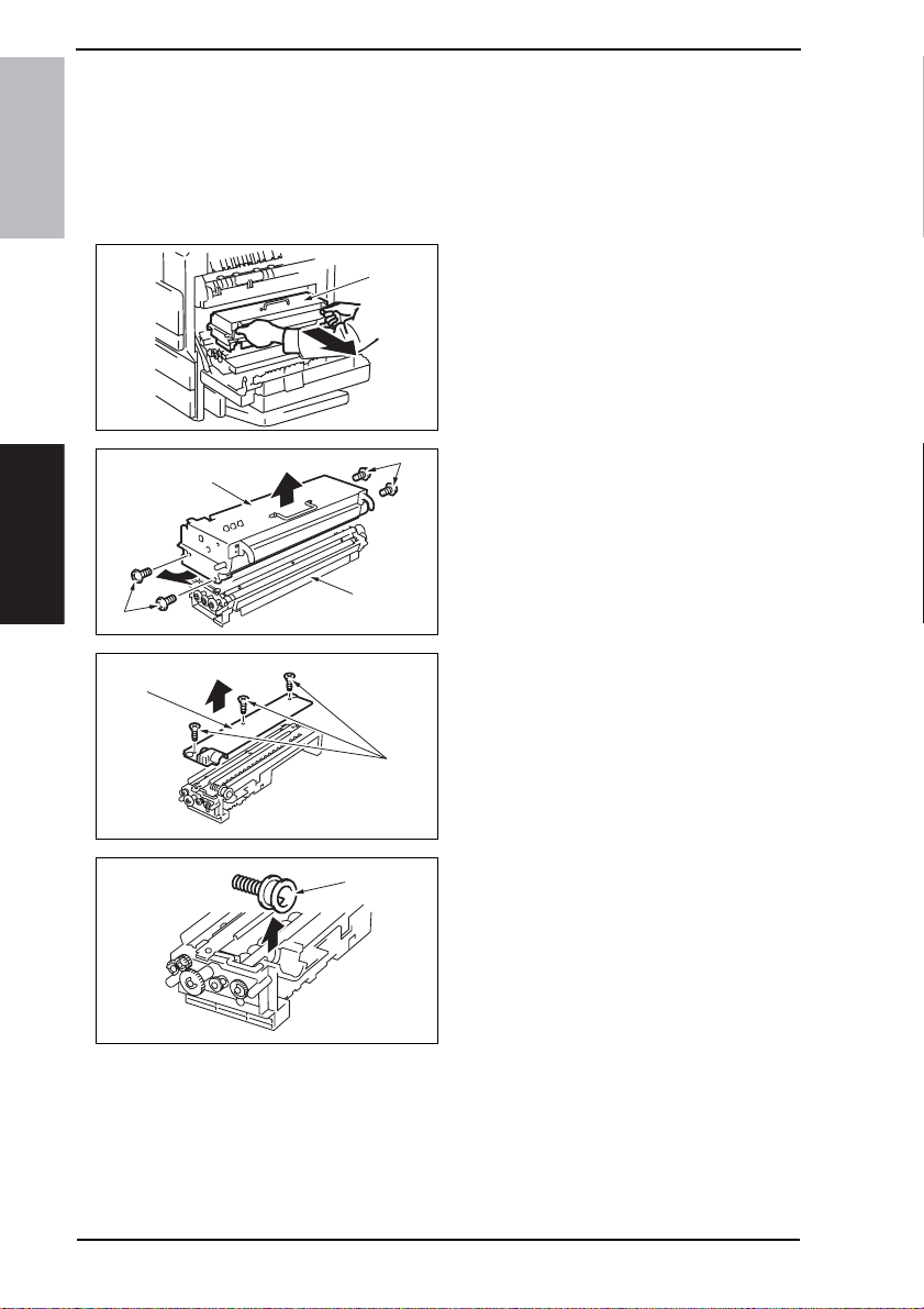
4. Periodical check Field Service Ver. 1.0 Aug. 2005
4.5.14 Replacement of the Developer
1. Select Tech. Rep. Mode → [Counter] → [Special Parts Counter] → [PC Life].
2. Press the Clear key to clear the counter value.
3. Turn OFF the main power switch.
NOTE
• Clear the PC Life counter before removing the IU.
bizhub 200/250/350
• After clearing the PC Life counter, be sure to turn OFF the main power switch.
4. Open the Right Door.
[1]
4040F2C555DA
5. Remove the IU [1].
Maintenance
[2]
[6]
[3]
[4]
4040F2C556DA
[5]
4040F2C579DA
[7]
4040F2C580DA
[2]
6. Remove four screws (silver) [2] and
disassemble the Photo Conductor
Unit [3] and the Developing Unit [4].
7. Remove three screws [5] and the
Developer Scattering Prevention
Plate [6].
8. Remove the Toner Supply Port [7].
34
Page 74

Field Service Ver. 1.0 Aug. 2005 4. Periodical check
9. Remove the developer [8].
[8]
[9]
[10]
4040F2C581DA
4040F2C582DA
4040F2C583DA
bizhub 200/250/350Maintenance
Removal of the Developer
• Dump the developer on the Sleeve
Roller by rotating the gear in the
direction of the arrow.
• If you rotate the gear in reverse,
mylar for cleaning the ATDC Sensor.
• Dump developer until almost no
developer sticks to the Sleeve
Roller.
10. Set the developer [9] while rotating
the gear in the direction of the arrow.
11. Reinstall the Toner Supply Port [10].
[12]
4040F2C584DA
[11]
4040F2C585DA
12. Using three screws [11], secure the
Developer Scattering Prevention
Plate [12].
35
Page 75

4. Periodical check Field Service Ver. 1.0 Aug. 2005
13. Install the four screws [13] to secure
[14]
[13]
[13]
bizhub 200/250/350
[15]
4040F2C586DA
the Photo Conductor Unit [14] and
Developing Unit [15].
14. Install the IU in the copier.
15. Turn ON the main power switch.
16. Select Tech. Rep. Mode → [Function] → [F8] and press the Start key.
NOTE
• After replacing the developer, be sure to execute F8 under Function of Tech. Rep.
Mode.
• When the main power switch is turned ON, execute F8 quickly.
Maintenance
36
Page 76

Field Service Ver. 1.0 Aug. 2005 4. Periodical check
4.6 Replacing the unit
4.6.1 Replacement of the Fusing Unit CAUTION
• From the safety viewpoint, the Fusing Unit is replaced as a unit. No parts intended
for other models should be used for the Fusing Unit of this machine. Note, however, that the thermistor and several other parts mentioned in this machine may be
replaced as an individual part with a new one.
1. Open the Right Door.
[2]
2. Remove the Rear Right Cover.
☞ 50
3. Remove the screw [1] and the Front
Right Cover [2].
bizhub 200/250/350Maintenance
[4]
[5]
[1]
4040F2C560DA
[3]
4040F2C563DA
[6]
[7]
4040F2C564DA
[8]
4040F2C565DA
4. Unplug two connectors [3] of the
Switch Back Unit.
5. Loosen the screw [4] in front.
6. Remove the screw [5] in front.
7. Loosen the screw [6] in the back.
8. Remove the screw [7] in the back.
9. Remove the Switch Back Unit [8].
37
Page 77

4. Periodical check Field Service Ver. 1.0 Aug. 2005
10. Remove the screw [9] and the Con-
[9]
[10]
bizhub 200/250/350
4040F2C658DA
nector Cover [10].
11. Remove two screws [11] and unplug
three connectors [12]. Then, remove
the Fusing Unit [13].
Maintenance
[13]
[12]
[11]
[12]
[12]
4040F2C566DA
4.6.2 Replacement of the Transfer Roller Unit
[1]
[1]
1. Open the Right Door.
2. Pull down the knobs [1] forward and
remove the Transfer Roller [2].
38
[2]
4040F2C554DA
Page 78

Field Service Ver. 1.0 Aug. 2005 4. Periodical check
4.6.3 Replacement of the Photo Conductor Unit
1. Select Tech. Rep. Mode → [Counter] → [Special Parts Counter] → [PC Life].
2. Press the Clear key to clear the counter value.
3. Turn OFF the main power switch.
NOTE
• Clear the PC Life counter before removing the IU.
• After clearing the PC Life counter, be sure to turn OFF the main power switch.
4. Open the Right Door.
[1]
4040F2C555DA
5. Remove the IU [1].
bizhub 200/250/350Maintenance
[2]
[3]
[4]
4040F2C556DA
[2]
6. Remove four screws (silver) [2] and
disassemble the Photo Conductor
Unit [3] and the Developing Unit [4].
7. Replace the Photo Conductor Unit
[3].
8. To reinstall, reverse the order of
removal.
NOTE
• Replace the Toner Filter (Develop-
ing Unit) with a new one at the same
time.
39
Page 79

4. Periodical check Field Service Ver. 1.0 Aug. 2005
4.6.4 Replacement of the Developing Unit
1. Select Tech. Rep. Mode → [Counter] → [Special Parts Counter] → [Developer].
2. Press the Clear key to clear the counter value.
3. Turn OFF the main power switch.
NOTE
• Clear the Developer counter before removing the IU.
bizhub 200/250/350
• After clearing the Developer counter, be sure to turn OFF the main power switch.
4. Open the Right Door.
[1]
4040F2C555DA
5. Remove the IU [1].
[3]
[2]
6. Remove four screws (silver) [2] and
disassemble the Photo Conductor
Unit [3] and the Developing Unit [4].
7. Replace the Developing Unit [4].
8. Supply new developer to the new
Maintenance
[2]
[4]
4040F2C556DA
Developing Unit.
☞ 34
9. Install the four screws [5] to secure
[6]
[5]
[5]
[7]
4040F2C587DA
the Photo Conductor Unit [6] and
Developing Unit [7].
10. Install the IU in the copier.
11. Turn ON the main power switch.
12. Select Tech. Rep. Mode → [Function] → [F8] and press the Start key.
NOTE
• After replacing the developer, be sure to execute F8 under Function of Tech. Rep.
Mode.
• When the main power switch is turned ON, execute F8 quickly.
40
Page 80

Field Service Ver. 1.0 Aug. 2005 5. Service tool
5. Service tool
5.1 CE Tool list
Tool name Shape Personnel Parts No. Remarks
bizhub 200/250/350Maintenance
Thermistor Holding/Check
Jig
4040F2C728DA
1 4040-7901-01
5.2 Copy materials
5.2.1 Developer
Parts name Replacing period
bizhub 350 100,000 copies
bizhub 250 80,000 copies
bizhub 200 65,000 copies
5.2.2 Photo Conductor Unit
Parts name Repl acing period
bizhub 350 100,000 copies
bizhub 250 80,000 copies
bizhub 200 65,000 copies
5.2.3 Toner Bottle
Parts name Replacing period
bizhub 350
bizhub 250
bizhub 200
5,000-copy Copy Kit 5,000 copies
15,000-copy Toner Kit 15,000 copies
5,000-copy Copy Kit 5,000 copies
10,000-copy Toner Kit 10,000 copies
41
Page 81

6. Firmware upgrade Field Service Ver. 1.0 Aug. 2005
6. Firmware upgrade
6.1 Preparations for Firmware rewriting
6.1.1 Service environment
• Drive which enables writing/reading of Compact flash
• Compact flash (with 32 MB or more)
bizhub 200/250/350
6.1.2 Writing into the Compact flash
• Copy the firmware files using the computer.
NOTE
• The copying operation should be performed on the files contained in the folder,
instead of the folder.
• Copy only those files to be upgraded to the compact flash.
• If wrong firmware is copied, no control panel display is given and thus no firmware
can be downloaded.
6.1.3 Checking ROM version
• Before attempting to upgrade the firmware, check the current ROM version.
☞ 196
Maintenance
6.2 Firmware rewriting
NOTE
• NEVER attempt to remove or insert the compact flash with the machine power
turned ON.
6.2.1 MSC
[1]
[2]
42
4040F2C596DA
4040F2C597DA
1. Turn OFF the main power switch.
2. Remove the Compact flash Cover
[1].
3. Insert the compact flash card [2], in
which only the MSC upgrading files
have been written, into the slot.
NOTE
• Make sure that this compact flash
card contains only the upgrading
firmware of the MSC, and not that of
the engine or Finisher.
Page 82
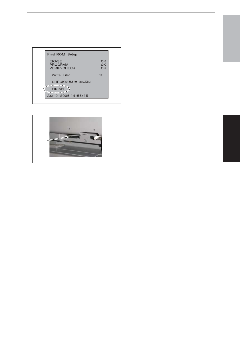
Field Service Ver. 1.0 Aug. 2005 6. Firmware upgrade
NOTE
• Be sure to turn ON the sub power switch first before turning ON the main power
switch.
4. Turn ON the main power switch.
5. The firmware upgrading sequence
will start.
6. When the upgrading sequence is
completed, which is notified by the
message “FINISH” appearing on the
screen, turn OFF the main power
switch.
NOTE
• NEVER turn OFF the main power
4040F2C749DA
switch until the message “FINISH”
appears on the screen.
7. Remove the Compact Flash [2] card
from the slot.
[2]
4040F2C597DA
8. Turn ON the main power switch.
9. Call the Tech. Rep. Mode to the screen.
☞ 148
10. Select [ROM Version].
11. Make sure if the version of Firmware is updated.
bizhub 200/250/350Maintenance
43
Page 83
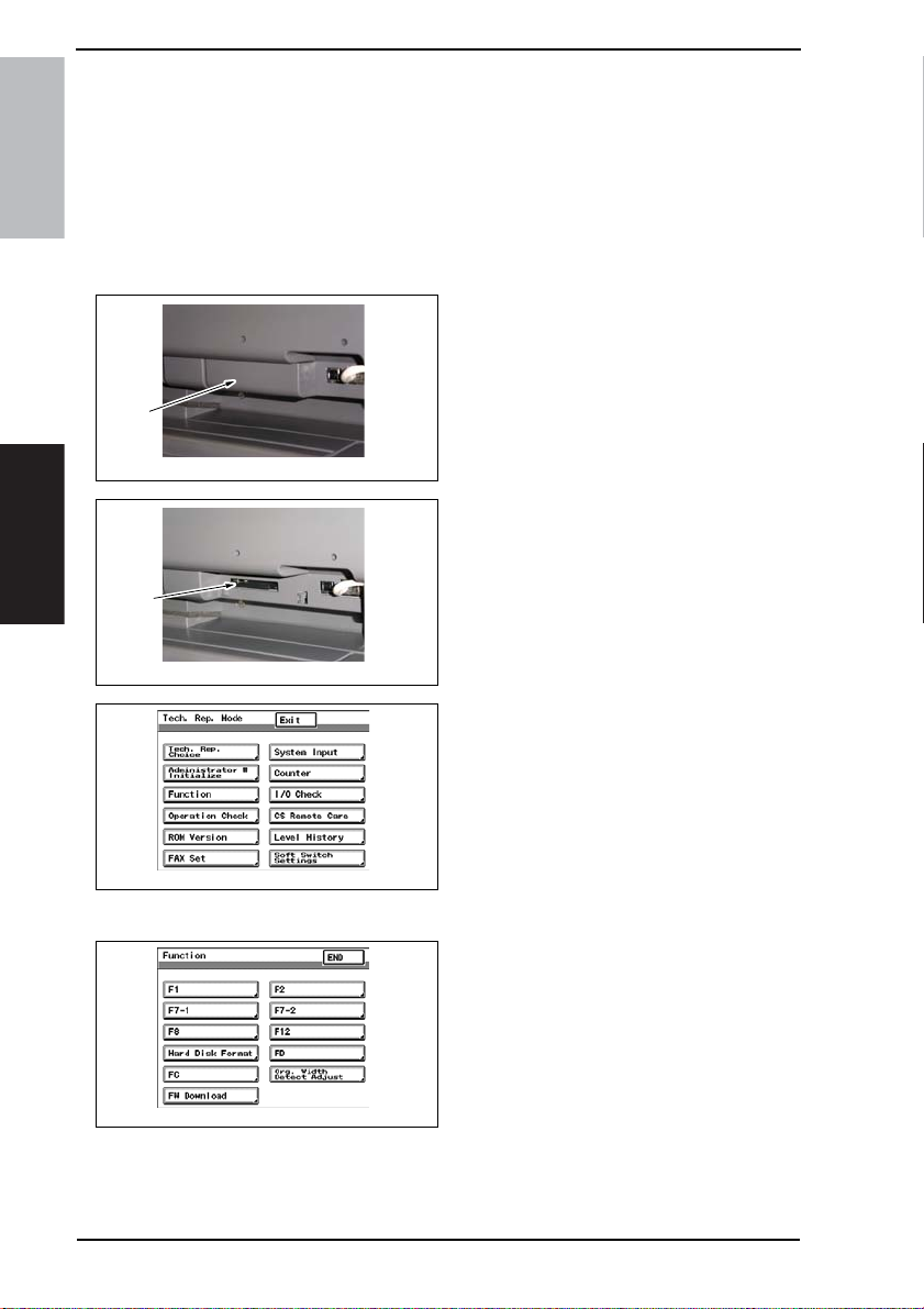
6. Firmware upgrade Field Service Ver. 1.0 Aug. 2005
6.2.2 Engine NOTE
• Make sure that the MSC firmware has not been copied to the compact flash card.
• To upgrade both the engine firmware and Finisher firmware at the same time, they
must first be copied onto a single compact flash.
☞ For the Finisher firmware upgrading procedures, see FS-508 Service Manual.
bizhub 200/250/350
• If the files copied to the compact flash card are those of either the engine or Finisher, or wrong, no screen display is given and thus no firmware can be downloaded.
1. Turn OFF the main power switch.
2. Remove the Compact flash Cover
[1].
[1]
4040F2C596DA
3. Insert the compact flash card [2], to
which the engine upgrading files
have been copied, into the slot.
Maintenance
[2]
4040F2C597DA
44
4040F2E767DA
4040F2E766DA
4. Open the Right Door.
NOTE
• Be sure to open the Right Door
before turning ON the main power
switch.
5. Turn ON the main power switch.
6. Call the Tech. Rep. Mode to the
screen.
☞ 148
7. Touch [Function].
8. Touch [FW Download].
Page 84
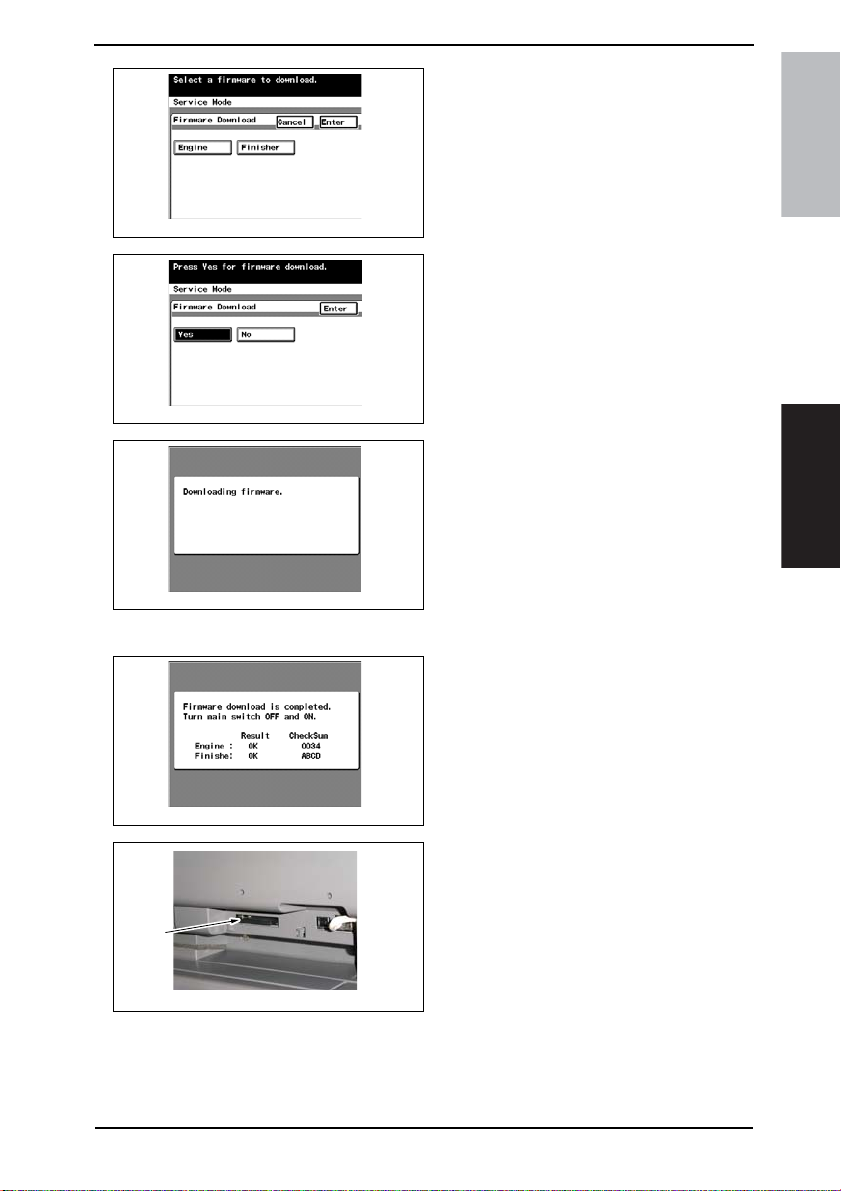
Field Service Ver. 1.0 Aug. 2005 6. Firmware upgrade
9. Select [Engine] and touch [Enter].
NOTE
• Touch [Finisher] also if the Finisher
firmware is to be upgraded at the
same time.
4040F2E768DA
10. Select [Yes] and touch [Enter].
4040F2E769DA
11. The firmware upgrading sequence
will start.
NOTE
• The firmware upgrading sequence
will last for 5 to 6 min. During this
period, NEVER turn off the machine
power.
4040F2E770DA
• If the Finisher firmware is also
upgraded, the entire sequence will
take about 10 to 11 min.
bizhub 200/250/350Maintenance
12. When the upgrading sequence is
4040F2E771DA
13. Remove the compact flash card [2]
[2]
4040F2C597DA
14. Call the Tech. Rep. Mode to the screen.
☞ 148
15. Select [ROM Version].
16. Make sure if the version of Firmware is updated.
completed, turn OFF the main power
switch.
from the slot. After some while thereafter, turn ON the main power switch.
45
Page 85

7. Other Field Service Ver. 1.0 Aug. 2005
7. Other
7.1 Disassembly/Adjustment prohibited items
A. Screws to which blue paint or green paint is applied
• Blue paint or green paint is applied to some screws to prevent them from coming
bizhub 200/250/350
loose.
• As a general rule, screws to which blue paint or green paint is applied should not
be removed or loosened.
B. Red-painted screws
• Do not remove or loosen any of the red-painted screws in the field. It should also
be noted that, when two or more screws are used for a single part, only one representative screw may be marked with the red paint.
C. Variable Resistors on Board
NOTE
• Do not turn the variable resistors on boards for which no adjusting instructions
are given in Adjustment/Setting.
D. Removal of PWBs
Maintenance
CAUTION
• When removing a circuit board or other electrical component, refer to “SAFETY
AND IMPORTANT WARNING ITEMS” and follow the corresponding removal procedures.
• The removal pr ocedures given in the following omit the remov al of connectors and
screws securing the circuit board support or circuit board.
• Where it is absolutely necessary to touch the ICs and other electrical components
on the board, be sure to ground your body.
46
Page 86

Field Service Ver. 1.0 Aug. 2005 7. Other
7.2 Disassembly/Assembly/Cleaning list (Other parts)
7.2.1 Disassembly/Assembly parts list
No Section Part name Ref .Page
1
2 Original Glass
3 Front Holding Bracket
4 Control Panel
5 Upper Front Cover
6Front Cover
7 Front Door
8 Lower Front Cover
9 Paper Output Cover
10 Left Cover
11 Rear Left Cover
12 Front Right Cover
13 Rear Right Cover
Exterior parts
14 Lower Right Rear Cover
15 Lower Right Cover
16 Rear Cover
17 Upper Rear Cover
18 Lower Rear Cover
19 Tray 1
20 Tray 2
21 Tray Rear Cover
22 Front Manual Bypass Cover
23 Rear Manual Bypass Cover
24 IR Right Cover
25 IR Left Cover
26 IR Upper Left Cover
27
28 MFBS Board
29 Inverter Board
30 BCRS Board
31 CCD Unit
Board and etc.
32 FD Paper Size Board 1
33 FD Paper Size Board 2
34 High Voltage Unit
35 Power Supply Unit
36 Operation Board
Original Scanning Glass
Mechanical Control Board Cover
☞ 49
☞ 49
☞ 49
☞ 56
☞ 53
☞ 53
☞ 51
☞ 52
☞ 52
☞ 54
☞ 54
☞ 50
☞ 50
☞ 49
☞ 55
☞ 51
☞ 50
☞ 49
☞ 56
☞ 57
☞ 49
☞ 55
☞ 55
☞ 51
☞ 54
☞ 49
☞ 57
☞ 62
☞ 63
☞ 64
☞ 65
☞ 58
☞ 59
☞ 61
☞ 60
☞ 69
bizhub 200/250/350Maintenance
47
Page 87

7. Other Field Service Ver. 1.0 Aug. 2005
No Section Part name Ref.Page
37
38 PH Unit
39 Toner Hopper Unit
Unit
40 Toner Replenishing Drive Unit
bizhub 200/250/350
Maintenance
41 D uplex Unit
42 Switc h Back Unit
43
44 Exposure Lamp
IR
45 Exposure Unit
46 Scanner Dr ive Cables
47
48 IU Motor
49 Fusing Unit Cooling Fan Motor
Others
50 Toner Suction Fan Motor
51 Temperature/humidity Sensor
52 ATDC Sensor
53
54 Paper Exit Roll 1
Fusing Unit
55 Paper Exit Roll 2
56 Separation Claw
Manual Bypass Unit ☞ 71
Scanner Motor
Main Motor
Thermistor
7.2.2 Cleaning parts list
☞ 71
☞ 74
☞ 74
☞ 76
☞ 76
☞ 77
☞ 79
☞ 78
☞ 80
☞ 85
☞ 85
☞ 86
☞ 86
☞ 87
☞ 87
☞ 89
☞ 91
☞ 91
☞ 92
No Section Part name Ref.Page
1
Bypass
2 Separation Roller
3
Tray1
4 Pick-up Roller
5 Separation Roller
6
Tray 2
7 Pick-up Roller
8 Separation Roller
9
Transpor t
10 Paper Dust Remover
11 Transport Roller
12
13 Bushings
14 Mirrors
IR
15 Lens
16 Original Scanning Glass
17 Original Glass
18
Others
19 Ds Collar
Feed Roller
Feed Roller
Feed Roller
Registration Roller
Scanner rails
Charge Neutralizing Plate
☞ 94
☞ 94
☞ 95
☞ 96
☞ 97
☞ 98
☞ 98
☞ 99
☞ 100
☞ 100
☞ 100
☞ 101
☞ 101
☞ 101
☞ 102
☞ 102
☞ 102
☞ 103
☞ 103
48
Page 88
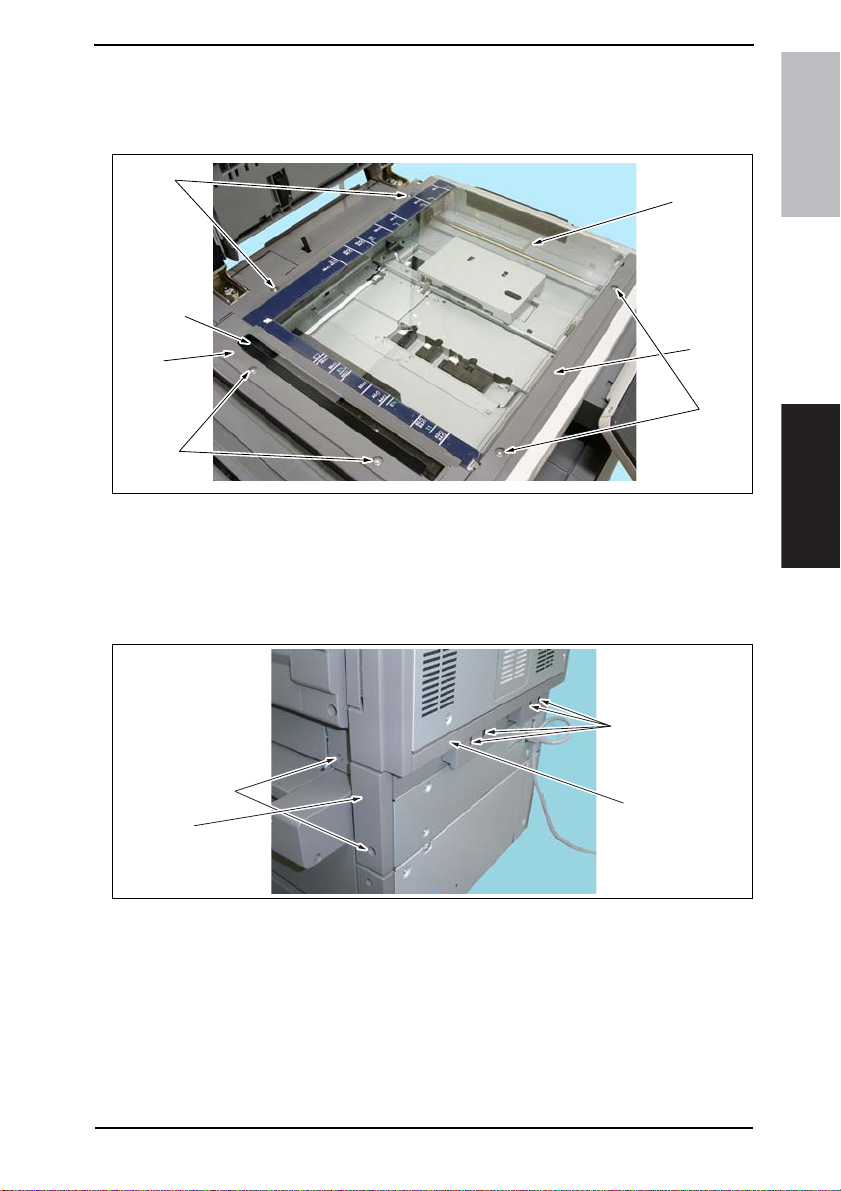
Field Service Ver. 1.0 Aug. 2005 7. Other
7.3 Disassembly/Assembly procedure
7.3.1 IR Upper Left Cover/Original Scanning Glass/Front Holding Bracket/Original Glass
[6]
[3]
[2]
[1]
1. Remove two Screws [1], and remove the IR Upper Left Cover [2].
2. Remove the Original Scanning Glass [3].
3. Remove two Screws [4], and remove the Front Holding Bracket [5].
4. Remove two Screws [6], and remove the Original Glass [7].
7.3.2 Lower Rear Cover/Lower Right Rear Cover/Tray Rear Cover
[1]
[7]
[5]
[4]
4040F2C677DA
bizhub 200/250/350Maintenance
[3]
[4]
1. Remove four Screws [1], and remove the Lower Rear Cover [2].
2. Remove two Screws [3], and remove the Lower Right Rear Cover [4].
[2]
4040F2C661DA
49
Page 89
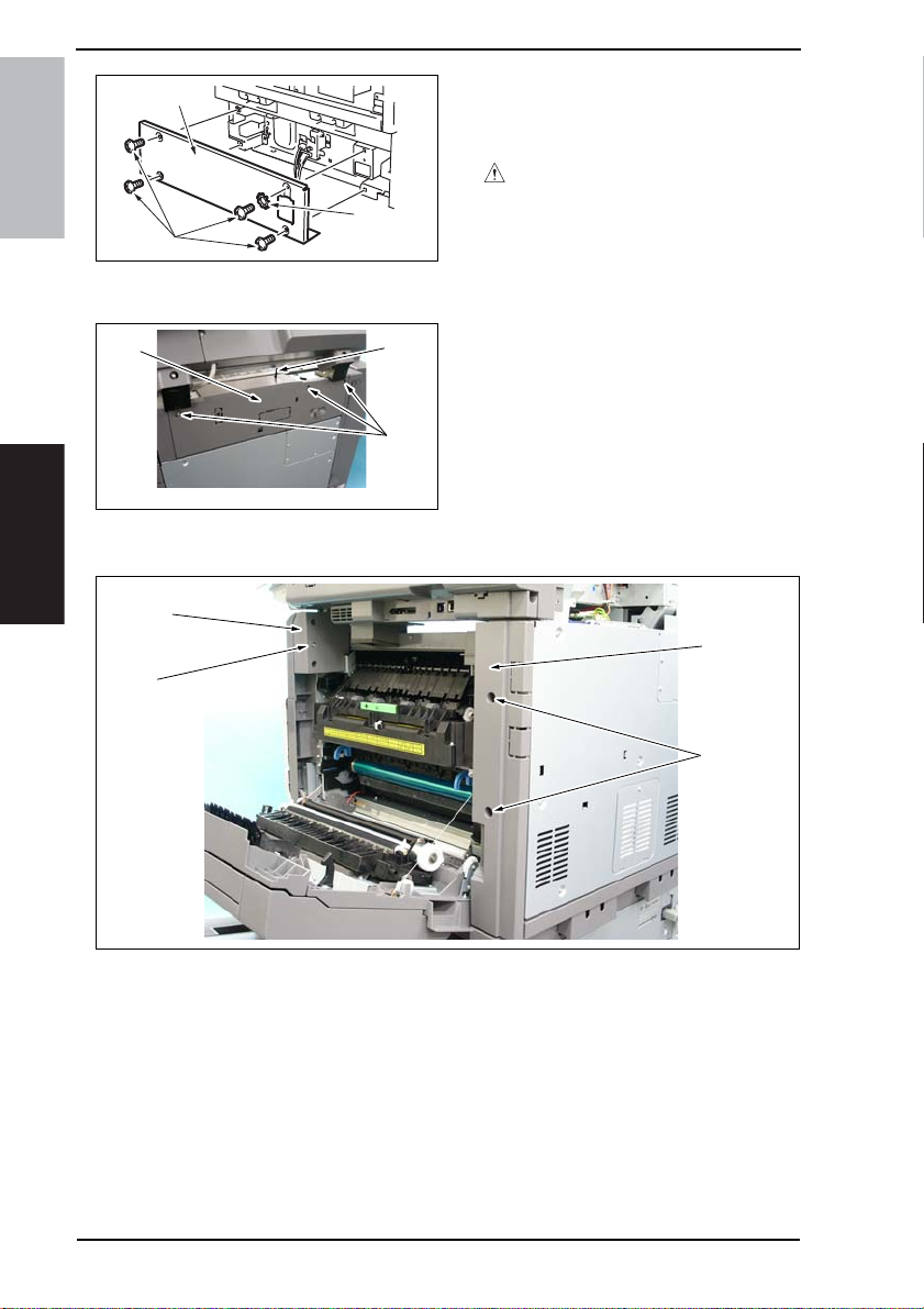
7. Other Field Service Ver. 1.0 Aug. 2005
[7]
bizhub 200/250/350
[5]
7.3.3 Upper Rear Cover
[3]
7.3.4 Rear Right Cover/Front Right Cover
Maintenance
[4]
[3]
[6]
4040F2C660DA
[2]
[1]
4040F2C662DA
3. Remove the four screws [5], one
wave washer [6], and the Tray Rear
Cover [7].
CAUTION
• Make sure that the wave washer is
installed at the correct position.
1. Remove three screws [1] and, pushing down the actuator [2], remove the
Upper Rear Cover [3].
[2]
1. Open the Right Door.
2. Remove two Screws [1], and remove the Rear Right Cover [2].
3. Remove the Screws [3], and remove the Front Right Cover [4].
50
[1]
4040F2C663DA
Page 90

Field Service Ver. 1.0 Aug. 2005 7. Other
7.3.5 IR Right Cover/Rear Cover
[1]
[2]
[2]
1. Open the Right Door.
2. Remove the Upper Rear Cover.
☞ 50
3. Remove the IR Right Cover [1].
4. Remove thirteen Screws [2], and remove the Rear Cover [3].
7.3.6 Front Door
1. Open the Front Door [1].
2. Remove the screw [2], C-clip [3], and
[3]
[2]
the Front Door [1].
[2]
[2]
[3]
4040F2C664DA
bizhub 200/250/350Maintenance
[1]
4040F2C665DA
51
Page 91
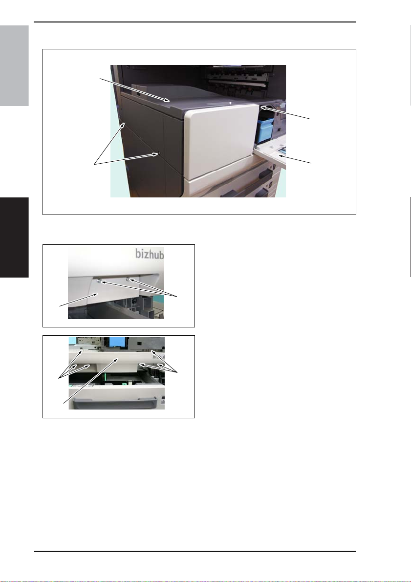
7. Other Field Service Ver. 1.0 Aug. 2005
7.3.7 Paper Output Cover/Lower Front Cover
[3]
bizhub 200/250/350
[2]
[2]
1. Open the Front Door [1].
2. Remove three screws [2] and the Paper Output Cover [3].
Maintenance
[4]
[5]
4040F2C666DA
[6]
[7]
[6]
4040F2C668DA
[1]
4040F2C575DA
3. Slide out the Tray 1.
4. Remove two screws [4] and the Con-
nector Cover [5].
5. Remove the Front Door.
☞ 51
6. Remove six screws [6] and the
Lower Front Cover [7].
52
Page 92

Field Service Ver. 1.0 Aug. 2005 7. Other
7.3.8 Upper Front Cover/Front Cover
1. Open the Right Door.
2. Remove the Front Right Cover.
☞ 50
3. Remove the screw [1] and the Upper
[1]
[2]
4040F2C667DA
Front Cover [2].
4. Remove the Toner Hopper Unit.
☞ 74
5. Remove the Paper Output Cover.
☞ 52
6. Remove the Front Door.
☞ 51
7. Remove the Lower Front Cover.
☞ 52
[4]
[3]
8. Remove five screws [3] and the Front
Cover [4].
bizhub 200/250/350Maintenance
[3]
4040F2C669DA
53
Page 93

7. Other Field Service Ver. 1.0 Aug. 2005
7.3.9 IR Left Cover/Rear Left Cover/Left Cover
[1]
bizhub 200/250/350
[2]
[4]
1. Remove the Upper Rear Cover.
☞ 50
2. Remove the IR Left Cover [1].
3. Remove two screws [2] and the Rear Left Cover [3].
Maintenance
4. Remove the Rear Cover.
☞ 51
5. Remove the Paper Output Cover.
☞ 52
6. Remove three screws [4] and the Left Cover [5].
[3]
[5]
4040F2C670DA
54
Page 94

Field Service Ver. 1.0 Aug. 2005 7. Other
7.3.10 Rear Manual Bypass Cover/Front Manual Bypass Cover/Lower Right Cover
[4]
[3]
[6]
1. Remove two screws [1] and the Rear Manual Bypass Cover [2].
2. Remove the screw [3] and the Front Manual Bypass Cover [4].
3. Remove the Manual Bypass Unit.
☞ 71
4. Remove two tabs [5] and the Lower Right Door Cover [6].
[5]
bizhub 200/250/350Maintenance
[2]
[1]
4040F2C671DA
55
Page 95

7. Other Field Service Ver. 1.0 Aug. 2005
7.3.11 Control Panel
1. Remove two screw covers [1].
bizhub 200/250/350
Maintenance
7.3.12 Tray 1
[2]
[1]
[2]
[2]
4040F2C592DA
4040F2C593DA
[4]
[3]
4040F2C594DA
2. Remove the four screws [2] on the
sides of the Control Panel.
3. Disconnect the connector [3] and
remove the Control Panel [4].
1. Slide out the Tray 1 [3].
2. Remove the screw [1] and, holding
the stopper [2], remove the Tray 1
[3].
56
[3]
[1]
4040F2C508DA
Page 96
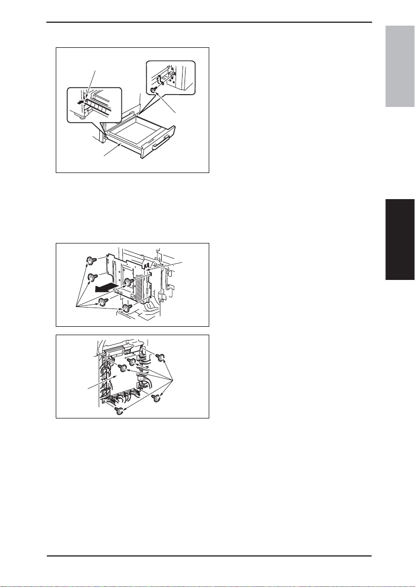
Field Service Ver. 1.0 Aug. 2005 7. Other
7.3.13 Tray 2
1. Slide out the Tray 2 [1].
[3]
2. Remove the screw [2] and, holding
the stopper [3], remove the Tray 2
[1].
[2]
bizhub 200/250/350Maintenance
[1]
4040F2C589DA
7.3.14 Mechanical Control Board Cover
1. Remove the Upper Rear Cover.
☞ 50
2. Remove the Rear Cover.
☞ 51
[2]
[1]
4040F2C561DA
[3]
[4]
4040F2C562DA
3. Remove five screws [1] and the
Mechanical Control Board Cover [2].
4. Unplug the all connectors.
5. Remove five screws [3] and the
Mechanical Control Board [4].
NOTE
• When replacing the Mechanical
Control Board, be sure to replace
the EEPROM.
☞ 110
• When the Mechanical Control Board
has been replaced with a new one,
check the ROM version and
upgrade the firmware to the latest
version.
☞ 42
57
Page 97
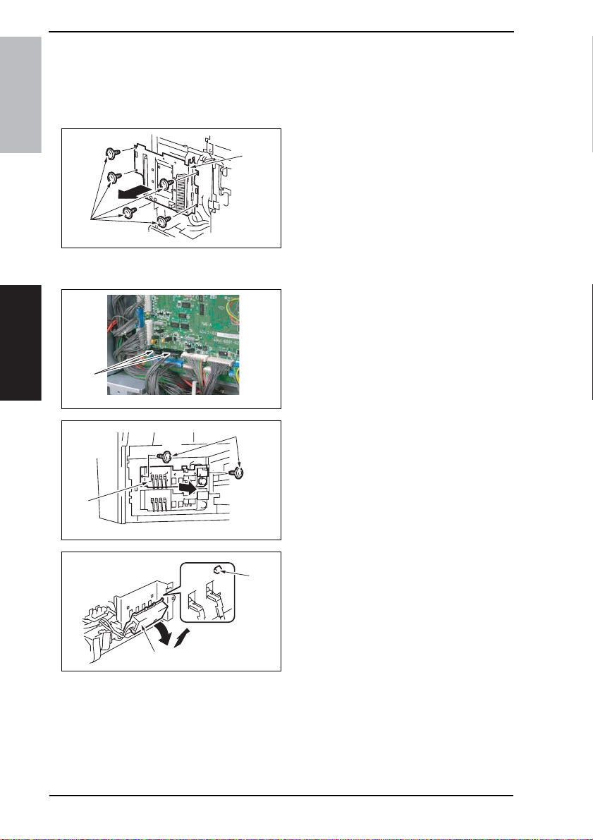
7. Other Field Service Ver. 1.0 Aug. 2005
7.3.15 FD Paper Size Board 1
1. Remove the Upper Rear Cover.
☞ 50
2. Remove the Rear Cover.
☞ 51
bizhub 200/250/350
[2]
[1]
4040F2C561DA
3. Remove five screws [1] and the
Mechanical Control Board Cover [2].
4. Remove the Tray 1.
☞ 56
5. Disconnect two connectors (PJ23,
PJ24) [3] from the Mechanical Control Board.
Maintenance
[5]
[3]
[7]
4040F2C656DA
[4]
4040F2C573DA
[6]
4040F2C572DA
6. Remove two screws [4] and the LiftUp Assy [5].
7. Remove four tabs [6] and the FD
Paper Size Board Assy [7].
58
Page 98
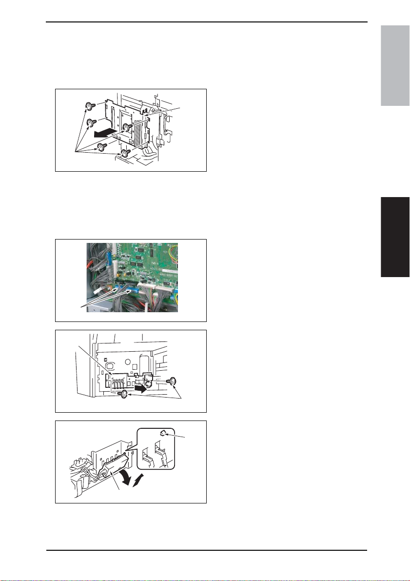
Field Service Ver. 1.0 Aug. 2005 7. Other
7.3.16 FD Paper Size Board 2
1. Remove the Upper Rear Cover.
☞ 50
2. Remove the Rear Cover.
☞ 51
3. Remove five screws [1] and the
[2]
[1]
4040F2C561DA
Mechanical Control Board Cover [2].
4. Remove the Tray Rear Cover.
☞ 49
5. Remove the Lower Rear Cover.
☞ 49
6. Remove the Tray 2.
☞ 57
7. Disconnect two connectors (PJ25,
PJ26) [3] from the Mechanical Control Board.
bizhub 200/250/350Maintenance
[5]
[3]
[7]
4040F2C657DA
[4]
4040F2C571DA
[6]
4040F2C572DA
8. Remove two screws [4] and the LiftUp Assy [5].
9. Remove four tabs [6] and the FD
Paper Size Board Assy [7].
59
Page 99
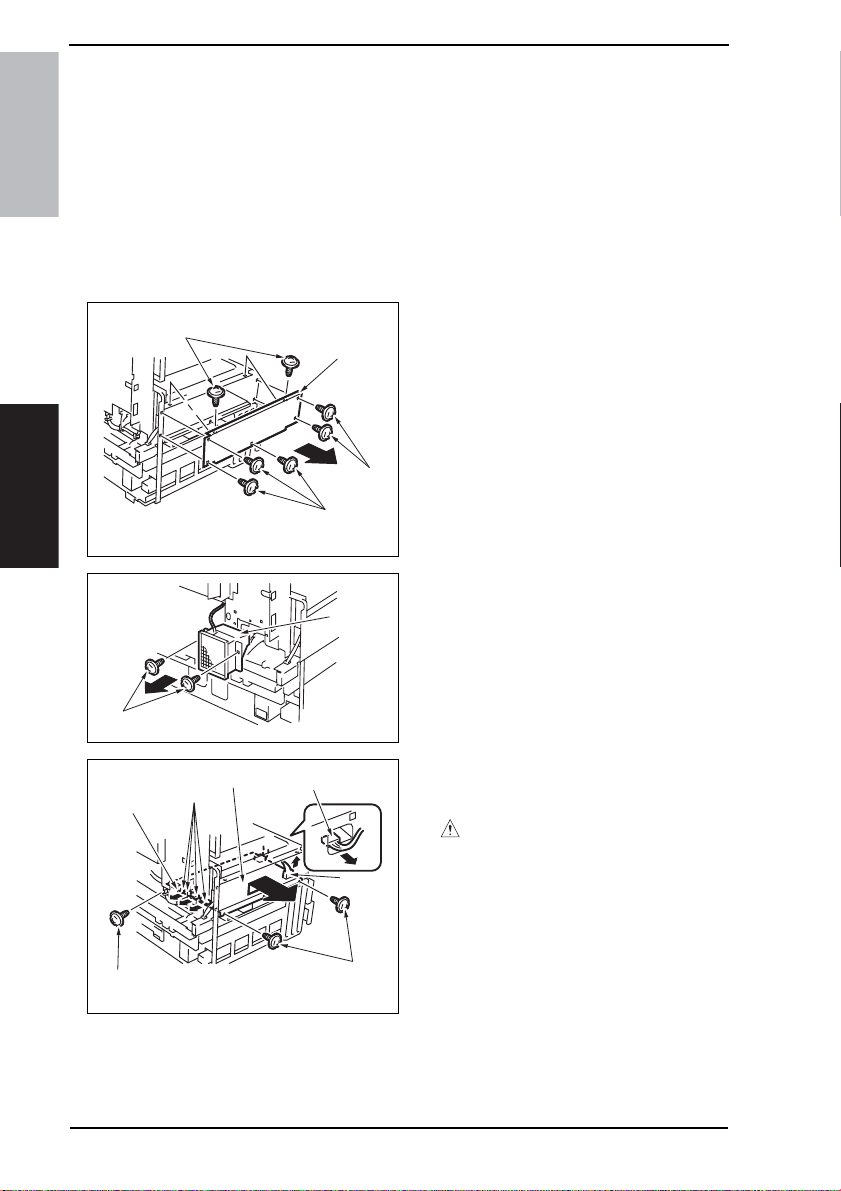
7. Other Field Service Ver. 1.0 Aug. 2005
7.3.17 Power Supply Unit
1. Remove the Paper Output Cover.
☞ 52
2. Remove the Upper Rear Cover.
☞ 50
3. Remove the Rear Cover.
bizhub 200/250/350
☞ 51
4. Remove the Rear Left Cover.
☞ 54
5. Remove the Left Cover.
☞ 54
6. Remove seven screws [1] and the
[1]
[2]
[1]
Power Supply Unit Cover [2].
Maintenance
[5]
[3]
[6]
[6]
[7]
[1]
4040F2C599DA
[4]
4040F2C601DA
[6]
[6]
[5]
4040F2C602DA
7. Remove two screws [2] and the
Power Supply Cooling Fan Motor [4].
8. Unplug seven connectors [5] and
remove three screws [6] and the
Power Supply Unit Assy [7].
CAUTION
• At reinstallation, make sure that the
harness is not slack.
60
Page 100
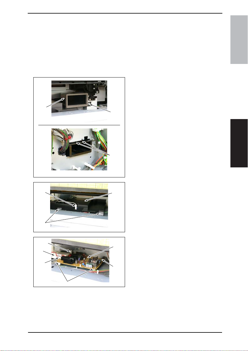
Field Service Ver. 1.0 Aug. 2005 7. Other
7.3.18 High Voltage Unit
1. Open the Right Door.
2. Remove the Imaging Unit.
3. Remove the Upper Rear Cover.
☞ 50
4. Remove the Rear Cover.
☞ 51
5. Remove the Toner Suction Fan Motor.
☞ 86
6. Remove the screw [1] and unhook
two tabs [2] on the rear side surface.
Then, remove the Toner Suction
Duct [3].
[3]
[1]
[2]
4040F2C672DA
bizhub 200/250/350Maintenance
[7]
[4]
[5]
[7]
[7]
[8]
[6]
4040F2C609DA
[9]
[7]
4040F2C610DA
7. Unplug the connector [4] and remove
two screws [5] and the High Voltage
Unit Cover [6].
8. Unplug four connectors [7] and
remove two screws [8] and the High
Voltage Unit [9].
61
 Loading...