

Page 1

Service Manual
Digital Copier
DEVELOP
D 2500iD
Page 2

Safety Precautions for Inspection and Service
When performing inspection and service procedures, observe the following precautions to
prevent accidents and ensure utmost safety.
✽
Depending on the model, some of the precautions given in the following do not apply.
Different markings are used to denote specific meanings as detailed below.
Indicates a potentially hazardous situation which, if not avoided,
WARNING
CAUTION
The following graphic symbols are used to giv e instructions that need to be observed.
Used to call the service technician’s attention to what is graphically represented
inside the marking (including a warning).
Used to prohibit the service technician’s from doing what is graphically represented inside the marking.
could result in death or serious injury.
Indicates a potentially hazardous situation which, if not avoided,
may result in minor or moderate injury. It may also be used to
alert against unsafe practices.
Used to instruct the service technician’s to do what is graphically represented
inside the marking.
WARNING
1. Always observe precautions.
•
Parts requiring special attention in this product will include a label containing the
mark shown on the left plus precautionary notes. Be sure to observe the precautions.
•
Be sure to observe the “Safety Information” given in the Operator’s Manual.
2. Before starting the procedures, be sure to unplug the power cord.
•
This product contains a high-voltage unit and a circuit with a large current
capacity that may cause an electric shock or burn.
•
The product also contains parts that can jerk suddenly and cause injury.
•
If this product uses a laser, laser beam leakage may cause eye damage or
blindness.
3. Use the specified parts.
•
For replacement parts, always use the genuine parts specified in the manufacturer’s parts manual. Installing a wrong or unauthorized part could cause
dielectric breakdown, overload, or undermine safety devices resulting in possible electric shock or fire.
•
Replace a blown electrical fuse or thermal fuse with its corresponding genuine
part specified in the manufacturer’s parts manual. Installing a fuse of a diff erent
make or rating could lead to a possible fire. If a thermal fuse blows frequently,
the temperature control system may have a problem and action must be taken
to eliminate the cause of the problem.
P-1
Page 3
4. Handle the power cord with care and never use a multiple outlet.
•
Do not break, crush or otherwise damage the power cord. Placing a heavy
object on the power cord, or pulling or bending it may damage it, resulting in a
possible fire or electric shock.
•
Do not use a multiple outlet to which any other appliance or machine is connected.
•
Be sure the power outlet meets or exceeds the specified capacity.
5. Be careful with the high-voltage parts.
•
A part mar ked with the symbol shown on the left carries a high voltage. Touching it could result in an electric shock or burn. Be sure to unplug the power cord
before servicing this part or the parts near it.
6. Do not work with wet hands.
•
Do not unplug or plug in the power cord, or perform any kind of service or
inspection with wet hands. Doing so could result in an electric shock.
7. Do not touch a high-temperature part.
•
A part mar ked with the symbol shown on the left and other parts such as the
exposure lamp and fusing roller can be very hot while the machine is energiz ed.
Touching them may result in a burn.
•
Wait until these parts have cooled down before replacing them or any surrounding parts.
8. Maintain a grounded connection at all times. (This item may not apply in the USA.)
•
Be sure to connect the ground wire to the ground terminal even when performing an inspection or repair. Without proper grounding, electrical leakage could
result in an electric shock or fire.
•
Nev er connect the ground wire to a gas pipe, water pipe, telephone ground wire,
or a lightning conductor.
9. Do not remodel the product.
•
Modifying this product in a manner not authorized by the manuf acturer may
result in a fire or electric shock. If this product uses a laser, laser beam leakage
may cause eye damage or blindness.
10. Restore all parts and harnesses to their original positions.
•
To promote safety and prevent product damage, make sure the harnesses are
returned to their original positions and properly secured in their clamps and saddles in order to avoid hot parts, high-voltage parts, sharp edges, or being
crushed.
•
To promote safety, make sure that all tubing and other insulating materials are
returned to their original positions. Make sure that fl oating components mounted
on the circuit boards are at their correct distance and position off the boards.
P-2
Page 4
CAUTION
1. Precautions for Service Jobs
•
A toothed washer and spring washer, if used originally, must be reinstalled.
Omitting them may result in contact failure which could cause an electric shock
or fire.
•
When reassembling parts, make sure that the correct screws (size, type) are
used in the correct places. Using the wrong screw could lead to stripped
threads, poorly secured parts, poor insulating or grounding, and result in a malfunction, electric shock or injury .
•
Take great care to avoid personal injury from possible burrs and sharp edges on
the parts, frames and chassis of the product.
•
When moving the product or removing an option, use care not to injure your
back or allow your hands to be caught in mechanisms.
2. Precautions for Servicing with Covers and Parts Removed
•
Wherever f easible, keep all parts and covers mounted when energizing the
product.
•
If energizing the product with a cover removed is absolutely unav oidable, do not
touch any exposed live parts and use care not to allow your clothing to be
caught in the moving parts. Never leave a product in this condition unattended.
•
Nev er place disassembled parts or a container of liquid on the product. Parts
falling into, or the liquid spilling inside, the mechanism could result in an electric
shock or fire.
•
Nev er use a flammable spray near the product. This could result in a fire.
•
Make sure the power cord is unplugged before removing or installing circuit
boards or plugging in or unplugging connectors.
•
Always use the int erlock switch actuating jig to actuate an interlock swit ch when
a cover is opened or removed. The use of folded paper or some other object
may damage the interlock switch mechanism, possibly resulting in an electric
shock, injury or blindness.
3. Precautions for the Working Environment
•
The product must be placed on a flat, level surface that is stable and secure.
•
Never place this product or its parts on an unsteady or tilting workbench when
servicing.
•
Provide good ventilation at regular intervals if a service job must be done in a
confined space for a long period of time.
•
Avoid dusty locations and places exposed to oil or steam.
•
Avoid working positions that may block the ventilation ports of the product.
4. Precautions for Handling Batteries
•
Replace a rundown battery with the same type as specified in the manufacturer’s parts manual.
•
Before installing a new battery, make sure of the correct polarity of the installation or the battery could burst.
•
Dispose of used batteries according to the local regulations. Never dispose of
them at the user’s premises or attempt to try to discharge one.
P-3
Page 5
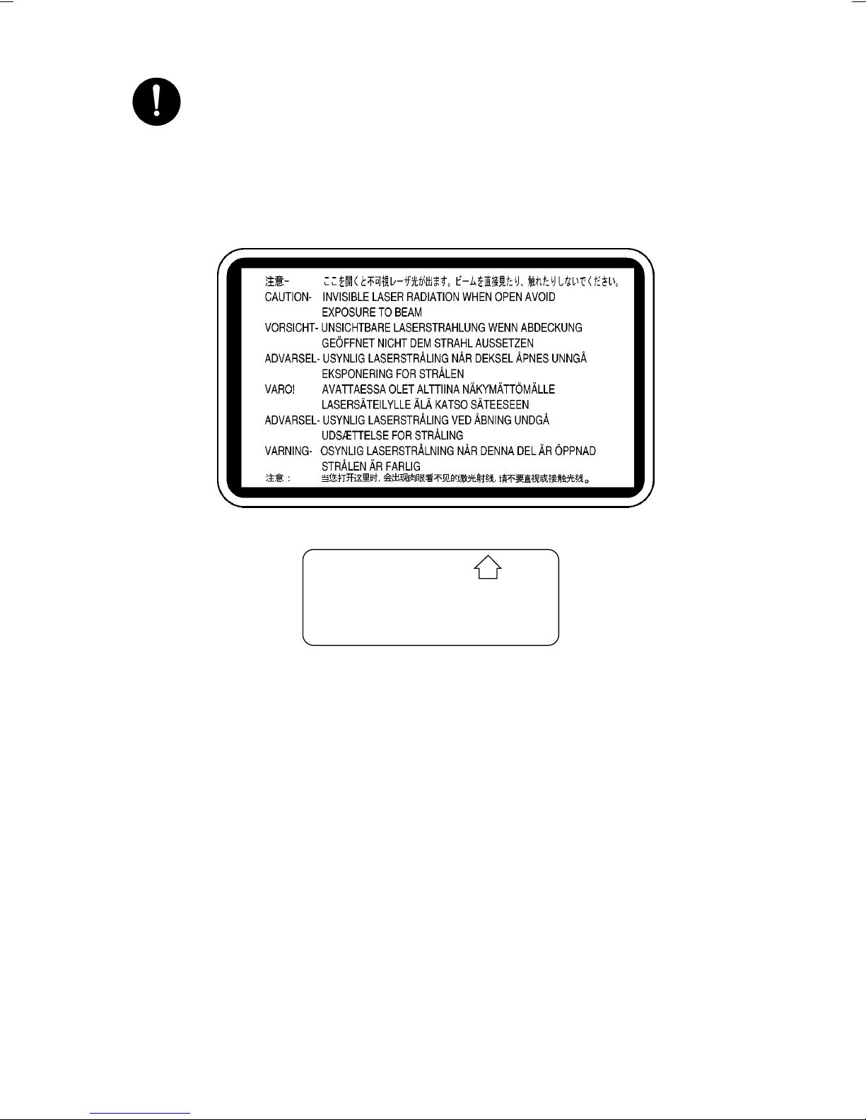
5. Precautions for the Laser Beam (Only for Products Employing a Laser)
•
Removing the cover marked with the following caution label could lead to possible exposure to the laser beam, resulting in eye damage or blindness. Be sure
to unplug the power cord before removing this cover.
•
If removing this cover while the pow er is ON is una v oidab le , be sure to wear protective laser goggles that meet specifications.
•
Make sure that no one enters the room when the machine is in this condition.
•
When handling the laser unit, observe the “Precautions for Handling Laser
Equipment.”
.
DANGER
Invisible laser radiation when open.
AVOID DIRECT EXPOSURE
TO BEAM
0947-7127-01
1144D270AA
1167P001AA
P-4
Page 6

Other Precautions
•
To reassemble the product, reverse the order of disassembly unless otherwise specified.
•
While the product is energized, do not unplug or plug connectors into the circuit boards
or harnesses.
•
The magnet roller generates a strong magnetic field. Do not bring it near a watch, floppy
disk, magnetic card, or CRT tube.
•
An air gun and vacuum cleaner generates a strong electrostatic charge that can destroy
the ATDC sensor and other sensors. Before cleaning a component with one of these
devices, be sure to remove all the sensors. Otherwise, use a blower brush and cloth
when cleaning parts.
•
When handling circuit boards with MOS ICs, observe the “INSTRUCTIONS FOR HANDLING THE PWBs WITH MOS ICs” (applicable only to the products using MOS ICs).
•
The PC Drum is a very delicate component. Observe the precautions given in “HANDLING OF THE PC DRUM” because mishandling may result in serious image problems.
•
Note that replacement of a circuit board may call for readjustments or resetting of particular items, or software installation.
•
After completing a service job, perform a safety check. Make sure that all parts, wiring
and screws are returned to their original positions.
•
Check the area surrounding the service site for any signs of damage, wear or need of
repair.
•
Do not pull out the toner hopper while the toner bottle is turning. This could result in a
damaged hopper motor or locking mechanism.
•
If the product is to be run with the front door open, make sure that the toner hopper is in
the locked position.
P-5
Page 7

Used Batteries Precautions
ALL Areas
CAUTION
Danger of explosion if battery is incorrectly replaced.
Replace only with the same or equivalent type recommended by the manufacturer.
Dispose of used batteries according to the manufacturer’s instructions.
Germany
VORSICHT!
Explosionsgefahr bei unsachgemäßem Austausch der Batterie.
Ersatz nur durch denselben oder einen vom Hersteller empfohlenen ähnlichen Typ.
Entsorgung gebrauchter Batterien nach Angaben des Herstellers.
France
ATTENTION
Ily a danger d’explosion s’ily a remplacement incorrec de la batterie.
Remplacer uniquement avec une batterie du meme type ou d’un type équivalent recommande par le constructueur.
Mettre au rebut les batteries usageés conformément aux instructions du fabricant.
Denmark
AD VARSEL!
Lithiumbatteri - Eksplosionsfare ved fejlagtig håndtering Udskiftning må kun ske med batteri af samme fabrikat og type.
Levér det brugte batteri tilbage til leverandøren.
Norway
ADVARSEL
Eksplosjonsfare ved feilaktig skifte av batteri.
Benytt samme batteritype eller en tilsvarende type anbefalt av apparatfabrikanten.
Brukte batterier kasseres i henhold til fabrikantens instruksjoner.
Sweden
VARNING
Explosionsfara vid felaktigt batteribyte.
Använd samma batterityp eller en ekvivalent typ som rekommenderas av apparattillverkaren.
Kassera använt batteri enligt fabrikantens instruktion.
Finland
VAROlTUS
Paristo voi räjähtää, los se on virheellisesti asennettu.
V aihda paristo ainoastaan laitevalmistajan suosittelemaan tyyppiin. Hävitä Käytetty paristo
valmistajan ohjeiden mukaisesti.
P-6
Page 8

D 2500iD
GENERAL
Page 9

CONTENTS
1. SAFETY INFORMATION .......................................... .................................. .....G-1
2. SPECIFICATIONS ........................................................................................... G-8
3. PRECAUTIONS FOR INSTALLATION ......... ....................... ............................G-10
4. PRECAUTIONS FOR USE .......... .................................. ................................. .G-11
5. HANDLING OF THE CONSUMABLES .................. ............. ............................G-12
6. OTHER PRECAUTIONS .................................. .................................. .............G-12
7. SYSTEM OPTIONS ......................................................................................... G-13
i
Page 10
1170SBG0100A
1 SAFETY INFORMATION
Laser Safety
This is a digital machine which prints by means of a laser. There is no possibility of danger
from the laser, provided the machine is operated according to the instructions in this
manual.
Since radiation emitted by the laser is completely confined within protective housing, the
laser beam cannot escape from the machine during any phase of user operation.
This machine is certified as a Class 1 product. This means the machine does not produce
hazardous laser radiation.
CAUTION: The use of controls, adjustments or performance of procedures
other than those specified in this manual may result in hazardous radiation
exposure. Because of this, Develop strongly recommends that you operate
your copy machine only as described in this documentation.
Internal Laser Radiation
Maximum Average Radiation Power: 36.7µW at laser aperture of the print head unit
Wavelength: 770-810nm
This product employs a Class
The Laser Diode and Scanning Polygon Mirror are incorporated in the print head unit.
The print head unit is NOT A FIELD SERVICE ITEM.
Therefore, the print head unit should not be opened under any circumstances.
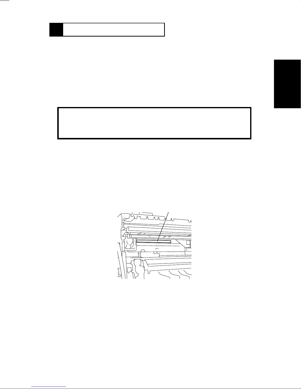
This figure shows the view inside the Right Si de Door with the
Imaging Unit removed.
III
b Laser Diode that emits an invisible laser beam.
Laser Aperture of the Print Head Unit
1166O263AA
For United States
CDRH regulation
This copier is certified as a Class 1 Laser product under the Radiation Performance
Standard according to the Food, Drug and Cosmetic Act of 1990. Compliance is mandatory
for Laser products marketed in the United States and is reported to the Center for Devices
and Radiological Health (CDRH) of the U.S. Food and Drug Administration of the U.S.
Department of Health and Human Services (DHHS). This means that the device does not
produce hazardous laser radiation.
G-1
Page 11

The label shown on page G-3 indicates compliance with the CDRH regulations and must
be attached to laser products marketed in the United States.
CAUTION:
specified in this manual may result in hazardous radiation exposure.
This is a semiconductor laser. The maximum power of the laser diode is 5mW and the
wav elength is 770-810nm.
For Europe
CAUTION:
specified in this manual may result in hazardous radiation exposure.
This is a semiconductor laser. The maximum power of the laser diode is 5mW and the
wav elength is 770-810nm.
For Denmark
ADVARSEL
Usynlig laserstråling ved åbning, når sikkerhedsafbrydere er ude af funktion.
Undgå udsættelse for stråling.
Klasse 1 laser produkt der opfylder IEC60825 sikkerheds kravene.
Use of controls, adjustments or perf ormance of procedures other than those
Use of controls, adjustments or perf ormance of procedures other than those
For Finland
LUOKAN 1 LASERLAITE
VAROITUS
Laitteen käyttäminen muulla kuin tässä käyttöohjeessa mainitulla ta v alla saattaa alt istaa
käyttäjän turvallisuusluokan 1 ylittävälle näkymättömälle lasersäteilylle .
VARO
Avattaessa ja suojalukitus ohitettaessa olet alttiina näkymättomälle lasersäteilylle. Älä
katso säteeseen.
For Sweden
KLASS 1 LASER APPARAT
VARNING
Om apparaten används på annat sätt än i denna bruksanvisning specificerats, kan
användaren utsättas för osynlig laserstrålning, som överskrider gränsen för laserklass 1.
VARNING
Osynlig laserstråining när denna del är öppnad och spärren är urkopplad. Betrakta ej
stråien.
G-2
Page 12
For Norway
CLASS 1 LASER PRODUCT
LASER KLASSE
1 PRODUKT
MINOLTA CO., LTD
2, Higashiakatsuchi, Yawata-cho, Toyokawa-shi
Aichi-ken 442-8585, Japan
MANUFACTURED:
THIS PRODUCT COMPLIES WITH 21 CFR
CHAPTER I, SUBCHAPTER J.
0946-7101-14
ADVERSEL
Dersom apparatet brukes på annen måte enn spesifisert i denne bruksanvisning, kan
brukeren utsettes för unsynlig laserstrålning, som overskrider grensen for laser klass 1.
Dette en halveder laser. Maksimal effekt till laserdiode er 5mW og bφlgelengde er 770810nm.
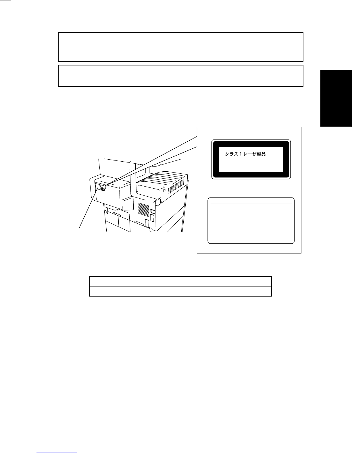
Laser Safety Label
A laser safety label is attached to the outside of the copy machine as shown below .
Laser safety label
For Europe
For United States
Manufacturer’s
Name Plate
1166O261DA
The Manufacturer’s Nam e Plate is affixed at the position illustrated above.
Please write down the Model Name and Serial No. of your copier here.
Model:
Serial No.:
1166O248AA
G-3
Page 13
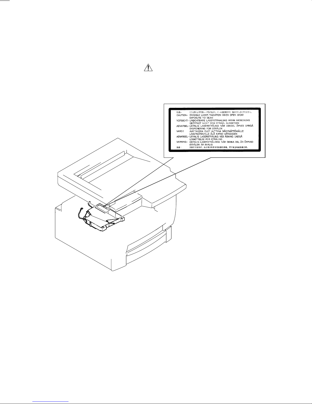
Label inside copy machine
The following laser safety label will be attached inside the copy machine as shown below.
Please read the following for your own protection.
Caution
Opening the cover indicated by the Caution label may e xpose y ou to harmful laser radiation
which could cause damage or loss of eyesight. Do not open the cover when the power is
on.
1166O234AA
G-4
Page 14

ALL Areas
Germany only
Denmark only
CAUTION
Danger of explosion if battery is incorrectly replaced.
Replace only with the same or equivalent type
recommended by the manufacturer.
Dispose of used batteries according
to the manufacturer’s instructions.
VORSICHT!
Explosinsgefahr bei unsachgemäßen austausch der
batterie. Ersatz nur durch denselben oder einen vom hersteller
empfohlenen ähnlichen typ. Entsorgung gebrauchter batterien
nach angaben des herstellers.
AD VARSEL!
Lithiumbatteri - Eksplosionsfare ved fejlagtig håndtering
Udskiftning må kun ske med batteri
af samme fabrikat og type.
Levér det brugte batteri tilbage til lever andøren.
Norway only
Sweden only
Finland only
ADVARSEL
Eksplosjonsfare ved feilaktig skifte av batteri.
Benytt samme batteritype eller en tilsvarende
type anbefalt av appar atfabrikanten.
Brukte batterier kasseres i henhold til fabrikantens
instruksjoner.
VARNING
Explosionsfara vid f elaktigt batteribyte.
Använd samma batterityp eller en ekvivalent
typ som rekommenderas av apparattillverkaren.
Kassera använt batteri enligt fabrikantens
instruktion.
VAROlTUS
Paristo voi räjähtää, los se on virheellisesti asennettu.
Vaihda paristo ainoastaan laitevalmistajan suosittelemaan
tyyppiin. Hävitä Käytetty paristo valmistajan ohjeiden
mukaisesti.
G-5
Page 15

ALL Areas
CAUTION
“Replace only with the same or equivalent type recommended by the manuf acturer.
Dispose of used IC Package according to the manufacturer’s instructions.”
Germany only
VORSICHT!
⇒
”Austausch nur durch denselben oder einen vom Hersteller empfohlenen,
gleichwertigen typ. Entsorgung gebrauchter Batterien nach Angaben des Herstellers.
G-6
Page 16

Service Precautions
(1) Precautions
Refer to DISASSEMBLY/CLEANING for the Disassembly procedure.
1. When unplugging connectors on the P.W.B.s themselves, always make sure the power
is OFF first. Be sure to unplug the copier before disassembling and cleaning.
2. Always unplug connectors by holding the connector housing. Pulling on the wires can
lead to problems with poor contact.
3. It is recommended that a body ground not be used when carrying out any troubleshooting procedure. Be sure to ground DC lines to a ground test point on the P.W.B.
(2) At Replacement/Adjustment/Cleaning
1. Be sure to handle the Fusing Unit carefully. It remains hot a while after the copier is
turned off.
2. Do not disassemble the Imaging Cartridge or Print Head Unit.
3. Do not expose the PC Drum of the Imaging Cartridge to direct sunlight or to room lighting for more than 5 minutes.
4. Turn off the power before removing the Print Head Unit to protect the e y es from possible
exposure to the laser beam.
5. Use only a Fuse of the indicated rating.
(3) During Operation
1. Keep your hands, clothing, etc. well away from operating or rotating parts.
2. Nev er touch the terminals of electrical parts or high voltage parts.
3. This copier uses an invisible laser beam. To prevent a laser beam leak, the copier performs a trial run to make sure the covers are in position.
Handling the P.W.B.
Observe the following precautions when handling a P.W. B. with ICs.
(1) During Transportation/Storage
1. During transport and storage, P.W.B.s should be kept in conductive bags or on mats
and not taken out unless absolutely necessary.
2. P.W.B.s should be stored in a place where direct sunlight does not strike them.
3. Do not touch IC terminals with your hands.
(2) At Replacement
1. Before removing connectors from a P.W.B., make sure the copier has been unplugged.
2. When P.W .B.s are tak en out of their conductiv e bags or off their mats, hold them by their
edges to avoid touching the terminals or the patterned surfaces.
3. Before installing connectors on a P.W.B., make sure the copier has been unplugged.
G-7
Page 17
1170SBG0200A
2 SPECIFICATIONS
TYPE : Console/Desktop Type
PHOTOCONDUCTOR : Organic Photoconductor
COPYING SYSTEM : Electrostatic Dry Powdered Image Transfer to Plain Paper
with a Laser
ORIGINAL SCANNING
RESOLUTION
PAPER FEEDING
SYSTEM
EXPOSURE SYSTEM : Mirror Scanning, Slit Exposure
DEVELOPING SYST EM : MT-HG System
CHARGING SYSTEM : Comb Electrode (1) DC Negative Corona with Scorotron
IMAGE TRANSFER : Roller Image Transfer
PAPER SEPARATING
SYSTEM
FUSING SYSTEM : Heat Roller
PAPER DISCHARGING
SYSTEM
MAXIMUM ORIGINAL
SIZE
: 600 dpi
: 3-way system Manual Feed Tray: Single sheet feeding
Multi-Purpose (MP) Cassette:
Plain paper: Approx. 250 sheets
Special paper: Approx. 20 sheets
500-Sheet Cassette: Approx. 500 sheets
System
: Paper Separator Fingers and Charge Neutralizing Plate
: Charge Neutralizing Brush
: A3L, 11” × 17”L
COPY MEDIUM
Paper Source MP Cassette Manual Feed Tray
2
Plain paper (60 to 90 g/m
Transparencies
Medium
Dimensions
❍
: Permissible−: Not permissible
MULTIPLE COPIES : 1 to 99
WARMING-UP TIME : 60 sec. or less with room temperature of 23°C and rated
FIRST COPY TIME : 5.8 sec. (A4C, MP Cassette, full size mode)
Thick paper (91 to 157 g/m
Postcards (190 g/m
Recycled paper
Maximum (Width × Length) 297 × 432 mm 297 × 432 mm
Minimum (Width × Length) 90 × 140 mm 90 × 140 mm
power voltage
5.9 sec. (8-1/2” × 11”C, MP Cassette, full size mode)
2
)
2
)
)
❍❍
❍❍
❍❍
❍❍
❍❍
G-8
Page 18

CONTINUOUS COPY SPEED (copies/min.)
- Metric - - Inch -
Size Speed Size Speed
A3L 14 11” × 17”L 14
B4L 16 8-1/2” × 14”L 17
A4L 19 8-1/2” × 11”L 20
A4C 25 8-1/2” × 11”C 25
B5L 22
B5C 29
ZOOM RATIOS
- Metric - - Inch -
Full Size
Enlargement
Fixed
Reduction
Variable 25% to 400% (in 0.1% increments)
×
1.000
×
2.000
×
1.414
×
1.224
×
1.154
×
0.866
×
0.816
×
0.707
×
0.500
×
1.000
×
2.000
×
1.545
×
1.294
×
1.214
×
0.785
×
0.733
×
0.647
×
0.500
LENS : Through Lens (F = 4.0, f = 62 mm)
EXPOSURE LAMP : Fluorescent Lamp
FUSING TEMPERATURE : 190°C
POWER/CURRENT CONSUMPTION (Copier Only)
Exposure Lamp
(Rating)
24V
20W
POWER
REQUIREMENTS
ENVIRONMENTAL CONDITIONS
Temperature 10 to 32°C with a fluctuation of 10°C or less per hour
Humidity 15 to 85% RH with a fluctuation of 10% RH or less per hour
Ambient Illumination 3,000 lux or less
Lev elness 1° (1.75 mm/100 mm)
Fusing Roller Heater
Lamp (Rating)
660W 850W
: 120V, 230V, 50/60Hz
Max. Power Consump-
tion (full system)
Max. Current Con-
sumption (full system)
120V, 8A
230V, 4A
DIMENSIONS : Width ... 566 mm, 22-1/4”
WEIGHT : 53.5 kg, 118 lbs.
Depth ... 707 mm, 27-3/4”
Height ... 635 mm, 25”
G-9
Page 19

1170SBG0300A
3 PRECAUTIONS FOR INSTALLATION
Installation Site
To ensure safety and utmost performance of the copier, the copier should NOT be used in a
place:
•
Where it will be subjected to extremely high or low temperature or humidity.
•
Which is exposed to direct sunlight.
•
Which is in the direct air stream of an air conditioner, heater or ventilator.
•
Which puts the operator in the direct stream of exhaust from the copier.
•
Which has poor ventilation.
•
Where ammonia gas might be generated.
•
Which does not have a stable, level floor.
•
Where it will be subjected to sudden fluctuations in either temperature or humidity. If a
cold room is quickly heated, condensation forms inside the copier, resulting in blank
spots in the copy.
•
Which is near any kind of heating device.
•
Where it may be splashed with water.
•
Which is dirty or where it will receive undue vibration.
•
Which is near volatile flammables or curtains.
Power Source
Use an outlet with a capacity of 120V/8A, or 220V to 240V/4A or more.
•
If any other electrical equipment is sourced from the same power outlet, make sure that
the capacity of the outlet is not exceeded.
•
Use a power source with little voltage fluctuation.
•
Never connect by means of a multiple socket any other appliances or machines to the
outlet being used for the copier.
•
Make the follo wing checks at frequent intervals:
✽
Is the power plug abnormally hot?
✽
Are there any cracks or scrapes in the cord?
✽
Has the power plug been inserted fully into the outlet?
✽
Does something, including the copier itself, ride on the power cord?
•
Ensure that the copier does not ride on the power cord or communications cable of other
electrical equipment, and that it does not become wedged into or underneath the mechanism.
Grounding
To prevent receiving electrical shocks in the case of electrical leakage, always ground the
copier.
•
Connect the ground wire to:
✽
The ground terminal of the outlet.
✽
A grounding contact which complies with the local electrical standards.
•
Nev er connect the ground wire to a gas pipe, the ground wire for a telephone, or a water
pipe.
G-10
Page 20

1170SBG0400A
4 PRECAUTIONS FOR USE
To ensure that the copier is used in an optimum condition, observe the following precautions.
•
Never place a heavy object on the copier or subject the copier to shocks.
•
Insert the power plug all the way into the outlet.
•
Do not attempt to remove any panel or cover which is secured while the copier is making
copies.
•
Do not turn OFF the Power Switch while the copier is making copies.
•
Provide good ventilation when making a large number of copies continuously.
•
Nev er use flammable sprays near the copier.
•
If the copier becomes inordinately hot or produces abnormal noise, turn it OFF and
unplug it.
•
Do not turn ON the Power Switch at the same time when you plug the po wer cord into the
outlet.
•
When unplugging the power cord, do not pull on the cord; hold the plug and pull it out.
•
Do not bring any magnetized object near the copier.
•
Do not place a vase or vessel containing water on the copier.
•
Be sure to turn OFF the P ower Switch at the end of the workday or upon power failure.
•
Use care not to drop paper clips, staples, or other small pieces of metal into the copier.
Operating Environment
The operating environmental requirements of the copier are as follows:
•
Temperature: 10°C to 32°C with a fluctuation of 10°C per hour
•
Humidity: 15% to 85% RH with a fluctuation of 10% RH per hour
Power Requirements
The power source voltage requirements are as follows:
•
Voltage Fluctuation: AC120/230V
±10% (Copying performance assured)
+10%
-15%
•
Frequency Fluctuation: 50/60 Hz ±0.3%
(Paper feeding performance assured)
G-11
Page 21

1170SBG0500A
5 HANDLING OF THE CONSUMABLES
Before using any consumable, always read the label on the container carefully.
•
Use the right toner. The applicable copier model name is indicated on the toner bottle.
•
Paper is easily damaged by dampness. To prevent absorption of moisture, store paper,
which has been removed from its wrapper but not loaded into the drawer, in a sealed
plastic bag in a cool, dark place.
•
Keep consumables out of the reach of children.
•
Do not touch the PC Drum with bare hands.
•
Store the paper, toner, and other consumables in a place free from direct sunlight and
away from any heating apparatus.
•
The same sized paper is of two kinds, short grain and long grain. Shor t grain paper
should only be fed through the copier crosswise, long grain paper should only be fed
lengthwise.
•
If your hands become soiled with toner, wash them with soap and water immediately.
•
Do not throw aw ay any used consumables (PC Drum, starter, t oner, etc.). They are to be
collected.
NOTE
Do not burn, bury in the ground, or throw into the water any consumables (PC Drum,
starter, toner, etc.).
1170SBG0600A
6 O T HE R PRECAUTIONS
The Print Head Unit of this copier uses a laser diode that emits a laser beam. Use the following precautions when performing service jobs at the users’ premises.
•
When a service job needs to be performed in the laser beam path, such as when working
around the Print Head Unit and PC Drum, be sure first to turn the copier OFF.
•
If the job requires that the power cord be left plugged in, observe the follo wing precautions
1. Take off your watch, ring, and any other reflective object and wear laser protective goggles.
2. At the job site, select a place that is as far as possible away from the users and that is
enclosed by walls.
3. Do not bring a highly reflective tool into the laser beam path during the service job.
G-12
Page 22
1170SBG0700A
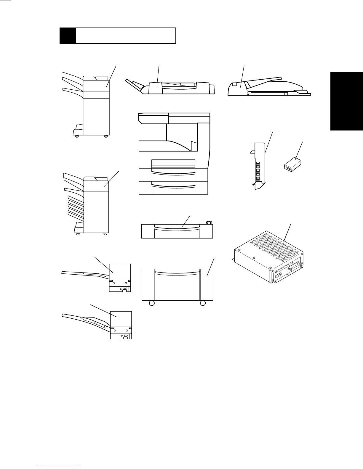
7 SYSTEM OPTIONS
1166O120AA
12
1
1166O014AA
2
1166O008AA
5
3
11
1166O015AA
1171G001AA
1145M035AA
7,8
4
1166O121AA
10
1166O012AA
9
1166O011AA
1. Duplexing Document F eeder (AFR-14)
2. Automatic Document Feeder (AF-6)
3. Plug-In Counter
4. Printer Controller (Pi3500)
5. Duplex Unit (AD-10)
6. Large Capacity Cabinet (PF-106)
1166O009AA
6
4608D018AA
1166O010AB
7. Paper Feed Unit (PF-108)
8. Paper Feed Unit (PF-110)
9. Shift Tray (OT-100)
10. Job Tray (JS-200)
11. Mailbin Finisher (FN-500)
12. Finisher (FN-100)
G-13
Page 23

D 2500iD
MECHANICAL/
ELECTRICAL
Page 24

CONTENTS
1. CROSS-SECTIONAL VIEW ............................................................................M-1
2. COPYING PROCESS ............................................. .................................. .......M-2
3. DRIVE SYSTEM ..............................................................................................M-4
4. OPERATING SEQUENCE ..............................................................................M-5
5. CPU OVERRUN MONITOR FUNCTION .........................................................M-8
6. IMAGE STABILIZATION SYSTEM ..................................................................M-9
7. IMAGING CARTRIDGE (I/C) ...........................................................................M-10
7-1. I/C Drive Mechanism .................................. ............. ............ ............. .......M-11
7-2. Identification and Life of I/C .....................................................................M-11
8. PC DRUM ........................................................................................................ M-12
9. DRUM CHARGING ..........................................................................................M-13
10. ERASE LAMP ..................................................................................................M-14
11. IR SECTION .................................................................................................... M-15
11-1. Exposure Section: Construction and Function .......................................M-16
11-2. Image Processing Flow ..........................................................................M-17
11-3. Original Size Detection ...........................................................................M-18
11-4. Original Size Detection Timing ............................................................... M-20
11-5. Scanner and 2nd/3rd Mirrors Carriage Moving Mechanism ...................M-21
12. PH SECTION ...................................................................................................M-22
12-1. PH Components .....................................................................................M-23
12-2. Laser Emission Timing (SOS Signal) .....................................................M-24
13. DEVELOPING UNIT .......... ............................................ ................................. .M-25
13-1. Sleeve/Magnet Roller .............................................................................M-26
13-2. Developing Bias ......................................................................................M-27
13-3. ATDC Sensor .........................................................................................M-28
13-4. Sub Hopper Toner Replenishing Mechanism .........................................M-29
13-5. Sub Hopper Toner Empty Detecting Mechanism ...................................M-30
13-6. Main Hopper Toner Replenishing Mechanism .......................................M-31
13-7. I/C Cooling Fan Motor ............................................................................M-32
13-8. Ozone Fan Motor ....................................................................................M-32
14. PAPER TAKE-UP/FEED SECTION ................................................................M-33
14-1. MP Cassette Paper Lifting Plate .............................................................M-33
14-2. MP Cassette-in-Position Detection .........................................................M-34
14-3. MP Cassette Paper Empty Detection .....................................................M-35
14-4. MP Cassette Paper Size Detection ........................................................M-36
14-5. Paper Take-Up Mechanism ....................................................................M-37
14-6. Manual Bypass Tray ...............................................................................M-37
14-7. Paper Take-Up Retry Mechanism ...................... .............. ......................M-38
15. SYNCHRONIZING ROLLERS .........................................................................M-39
15-1. Synchronizing Roller Drive Mechanism/Control .....................................M-39
15-2. Paper Dust Remover ..............................................................................M-40
16. IMAGE TRANSFER AND PAPER SEPARATION ...........................................M-41
17. PC DRUM PAPER SEPARATOR FINGERS ...................................................M-42
18. PC DRUM CLEANING ..................................................................................... M-43
i
Page 25

19. FUSING UNIT ..................................................................................................M-44
19-1. Drive Mechanism .................................................................................... M-45
19-2. Fusing Rollers Pressure Mechanism ......................................................M-45
19-3. Fusing Temperature Control ...................................................................M-46
19-4. CPM Control ...........................................................................................M-47
20. PAPER EXIT UNIT ..........................................................................................M-48
21. FUSING COOLING FAN MOTOR ...................................................................M-49
22. POWER UNIT COOLING FAN MOTOR ..........................................................M-50
ii
Page 26
1170SBM0100A
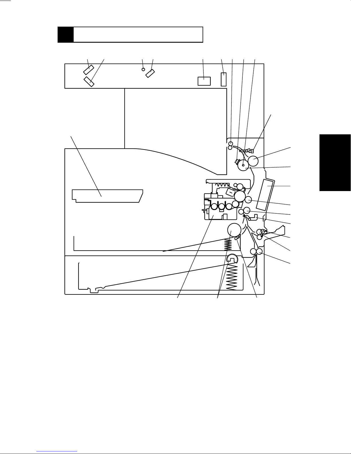
1 CROSS-SECTIONAL VIEW
23
12 5 6789
43
10
11
12
13
14
15
16
1. 2nd Mirror
2. 3rd Mirror
3. Exposure Lamp
4. 1st Mirror
5. Lens
6. CCD Unit
7. Paper Exit Roller
8. Fusing Roller Thermostat (TS1)
9. Fusing Roller Heater Lamp (H1)
10. Paper Exit Sensor (PC3)
11. Right Fusing Roller
12. Left Fusing Roller
2122
13. Fusing Cooling Fan Motor (M3)
14. Image Transfer Roller
15. Synchronizing Roller
16. Synchronizing Roller Sensor (PC2)
17. Manual Feed Paper Take-Up Sensor
(PC8)
18. Manual Feed Paper Take-Up Roll
19. Vertical Transpor t Roller
20. Paper Separator Pad
21. Paper Take-Up Roll
22. Imaging Cartridge (I/C)
23. PH Unit
20
1171M037AB
17
18
19
M-1
Page 27
1170SBM0200A
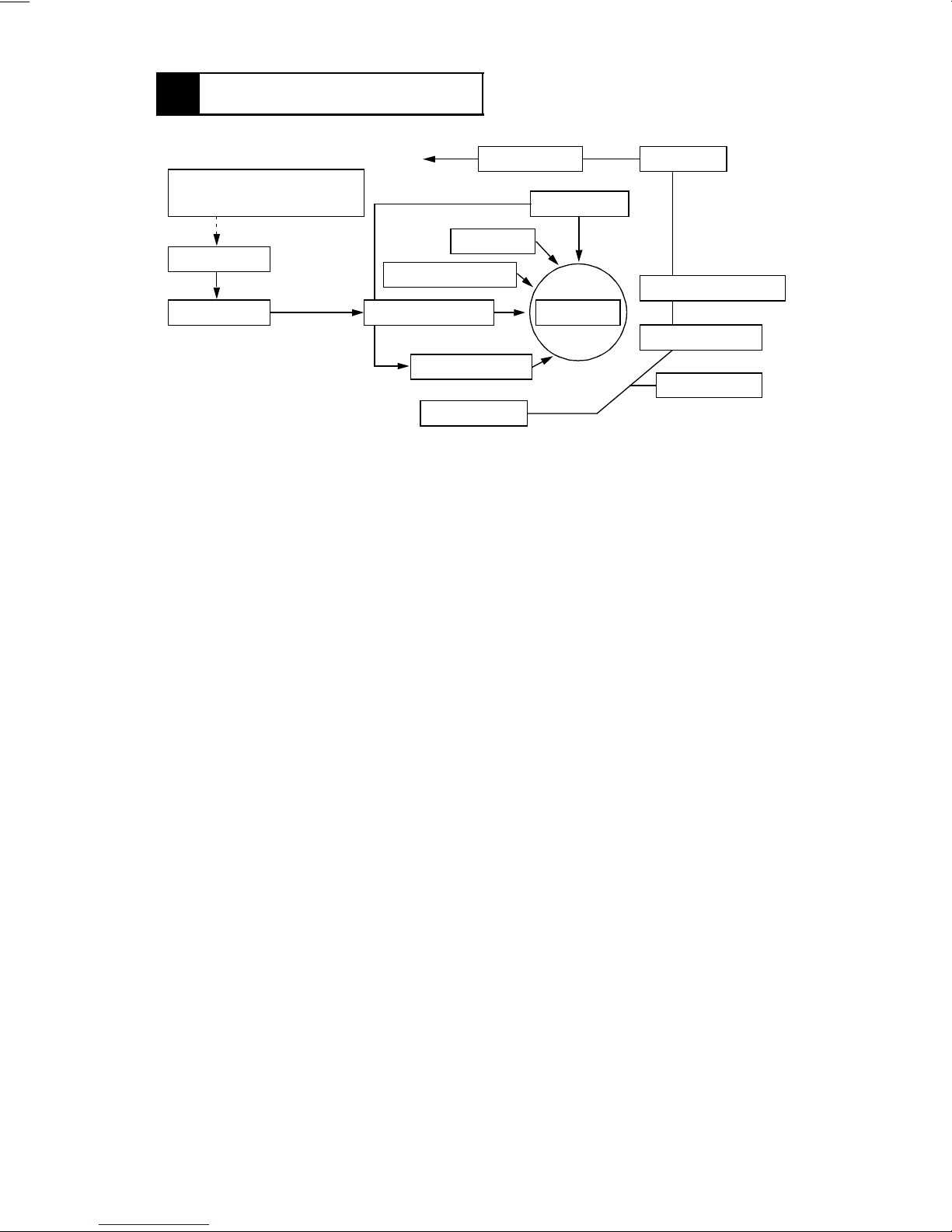
2 COPYING PROCESS
14. Paper Exit 13. Fusing
3. Photoelectric Conversion
Section
12. Erase
4. H GB Board
2. Drum Charging
5. MFB Board 1. PC Drum
6. Laser Exposure
7. Development
8. Paper Feed
1. PC Drum
•
The drum is an aluminum cylinder coated with photosensitive material on which an electrostatic latent image is produced.
11. Cleaning
10. Paper Separation
9. Image Transfer
8. Paper Feed
2. Drum Charging
•
A scorotron charger employing a comb electrode generates a negative DC charged
layer on the surface of the PC Drum.
3. Photoelectric Conversion Section
•
The Exposure Lamp directs light onto the original. The light reflected off the original is
directed and resized by the mirrors and lens so as to produce a reduced-size image on
the CCD Sensor.
4. HGB Board
•
Converts an electric signal into a corresponding 8-bit digital image signal (A/D conversion), makes various corrections, and outputs the results to the MFB Board.
5. MFB Board
•
Compresses the image data received from the HGB Board, stores it, and uncompresses it.
6. Laser Exposure
•
The laser beam emitted from the LD (laser diode) strikes the surface of the PC Drum,
creating an electrostatic latent image.
7. Development
•
Negatively charged toner adheres to the latent image on the PC Drum surface, creating
a visible image.
8. Paper Feed
•
Feeds sheets of paper from the appropriate paper source.
9. Image Transfer
•
An Image Transfer Roller is used. A positive charge applied to the roller causes the visible image on the surface of the PC Drum to transfer onto the front side of the paper.
M-2
Page 28

10. Paper Separation
•
The PC Drum Separator Fingers remove paper from the surface of the PC Drum.
11. Cleaning
•
The Cleaning Blade scrapes residual toner off the surface of the PC Drum and the toner
is recycled back to the Developing Unit.
12. Erase
•
The PC Drum is exposed to light, which effectively removes any residual charge from
the drum surface.
13. Fusing
•
Heat and pressure applied by the Right and Left Fusing Rollers fuse toner on the paper.
14. Paper Exit
•
Feeds paper out of the copier.
M-3
Page 29
1170SBM0300A
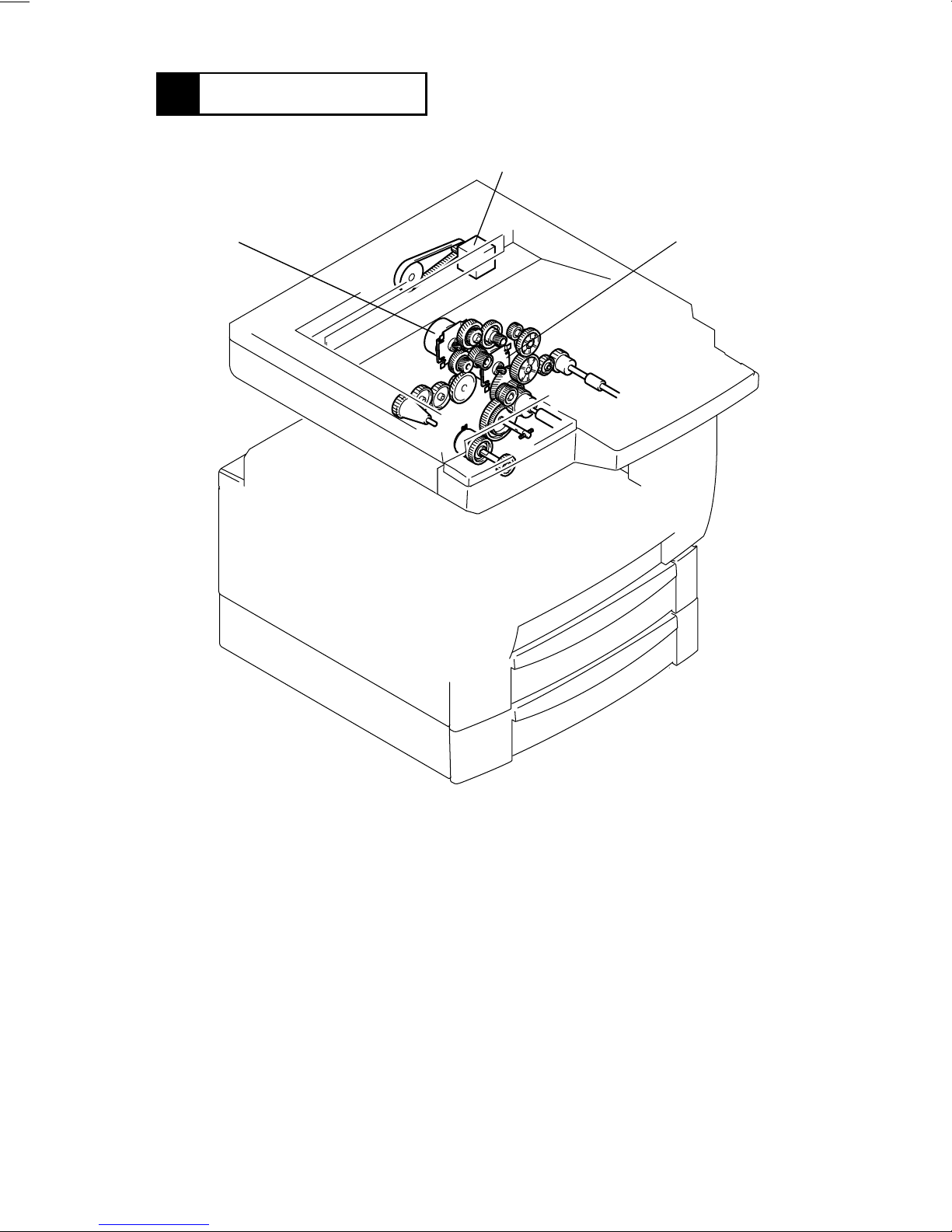
3 DRIVE SYSTEM
A
B
C
A. Scanner Motor (M5)
Drives the Scanner and 2nd/3rd Mirrors Carriage.
B. I/C Moto r (M1)
Drives the I/C Unit.
C. Main Motor (M2)
Drives the P aper Take-Up Roll, Manual Feed Paper Take-Up Roll, Synchronizing Roller,
Image Transfer Roller, and Fusing Unit.
1171M024AB
M-4
Page 30
1170SBM0400A
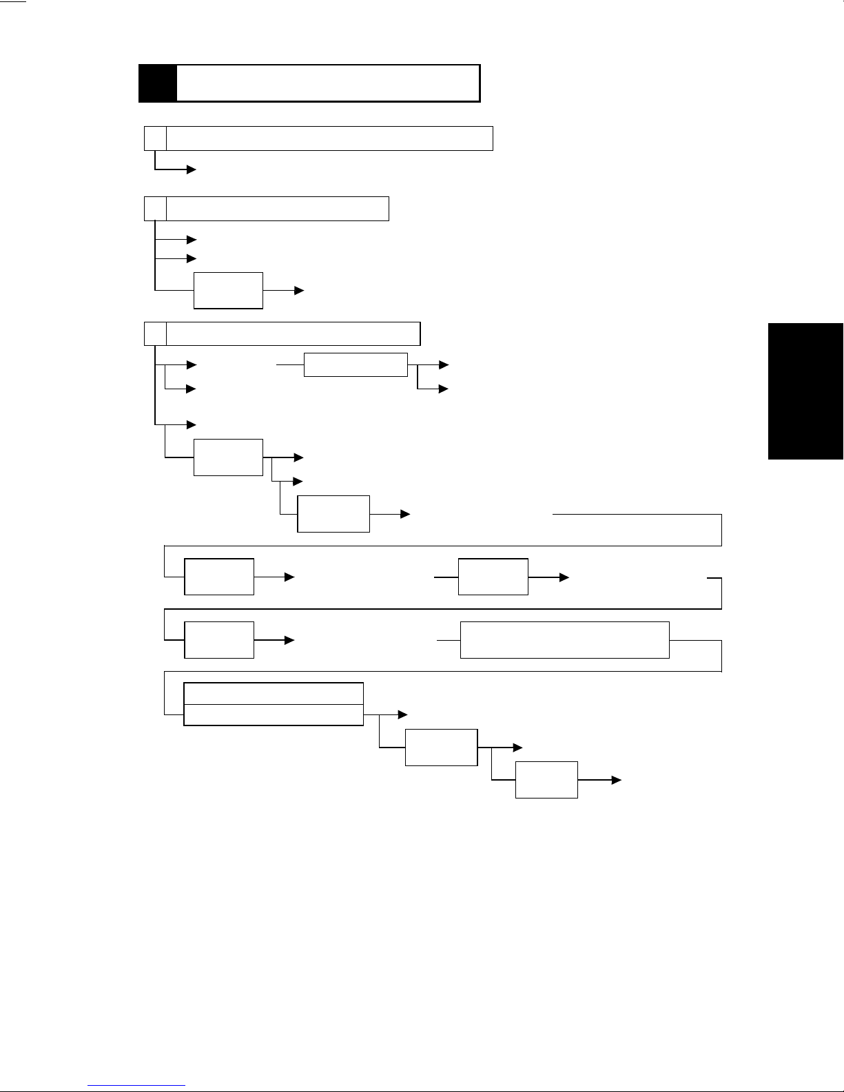
4 OPERATING SEQUENCE
A The power cord is plugged into the power outlet.
ON
B The Power Switch is turned ON.
ON
ON
The Power Supply Unit outputs DC24V for the Dehumidifying Heater (option).
DC voltage output
Control panel display
Approx.
560 msec.
ON
Fusing Roller Heater Lamp
C The warming-up cycle is completed.
ON
ON
Main Motor
Powe r Unit Co oling Fan Motor turns
at full speed.
Developing bias (DC)
Approx.
100 msec.
Approx.
400 msec.
Approx.
400 msec.
ON
ON
ON
Approx. 20 sec.
I/C Motor
ON
Image transfer output: - voltage
Approx.
700 msec.
Image transfer output:
- voltage
Image transfer output:
- voltage
ON
OFF
Predrive stops
Powe r Unit Cooling Fan Motor turns
at half speed.
Image transfer output:
+ voltage
Approx.
400 msec.
T/C ratio is checked for abnormality
for approx. 28 sec.
ON
Image transfer output:
+ voltage
Normal T/C
Abnormal T/C: approx. 31 sec.
OFF
I/C Motor
Approx.
400 msec.
M-5
OFF
Image transfer output
Approx.
15 min.
OFF
Developing bias
(DC)
Page 31

D The Start key is pressed.
ON
ON
Polygon Motor
Fusing Cooling Fan Motor
Approx. 6 sec.
ON
ON
Laser
Developing bias (DC)
Approx.
100 msec.
ON
Image transfer output: - voltage
ON
I/C Motor
Approx.
140 msec.
ON
Approx.
700 msec.
Main Motor
The Power Unit Cooling Fan Motor turns at full
speed.
The Ozone Fan Motor turns at full speed.
E The Synchronizing Roller Sensor is activated.
Approx.
110 msec.
VSYNC signal ON:
approx. 50 msec. later
OFF
Paper Take-Up Solenoid
ON
Paper Take-Up Solenoid
ON
Synchronizing Clutch
ON
Developing bias (AC)
Approx.
160 msec.
ON
Approx.
1.1 sec.
ON
Image transfer current value for printing
ON
Paper Take-Up Solenoid
Approx.
90 msec.
Image transfer current
value for non-printing
timing between sheets of
paper
OFF
Paper Take-Up
Solenoid
F The Synchronizing Roller Sensor is deactivated.
Approx.
130 msec.
Approx.
170 msec.
Approx.
320 msec.
OFF
OFF
ON
OFF
Synchronizing Clutch
Developing bias (AC)
Image transfer output: - voltage
Approx.
650 msec.
Laser
OFF
I/C Motor
Approx.
15 min.
M-6
OFF
Developing bias (DC)
Page 32

G T he Paper Exit Sensor is deactivated.
Approx.
680 msec.
OFF
OFF
Main Motor
The Power Unit Cooling Fan Motor turns at half speed.
Polygon Motor
Approx. 10 sec.
Approx. 20 sec.
OFF
OFF
Ozone Fan Motor
Fusing Cooling Fan Motor
M-7
Page 33

1170SBM0500A
5 CPU OVERRUN MONITOR FUNCTION
•
CPU Overrun Monitor Function (Watchdog Function)
The watchdog function is a self-monitoring function that determines whether any of the
CPUs mounted on the control board overrun.
•
If this function detects that a CPU overruns, the copier automatically resets the CPU,
thereby restarting the logic circuit and mechanism.
•
Even if a copier CPU operates erratically due to electrical noise, therefore, the copier is
able to recover from the f aulty condition so that the number of visits made by the Tech.
Rep. for CPU overrun can be minimized.
•
Processing performed during watchdog function:
If a faulty condition is detected, the copier resets the CPU and performs a restart
sequence. Since this sequence of operations is performed even during a copy cycle, the
copier detects a sheet or sheets of paper left inside it as a misfeed while it is being
restarted.
M-8
Page 34

1170SBM0600A
6 IMAGE STABILIZATION SYSTEM
•
The following image stabilization controls are provided to ensure stabilized copy image.
Item Purpose Control
PC Drum temperature
correction
PC Drum deterioration
correction
Grid Voltage: (Vg)
To compensate for any change
in ID due to changing PC Drum
temperatures.
To compensate for degraded
sensitivity caused by a deteriorating PC Drum.
PC Drum
Sleeve/
Magnet Roller
Developing Bias: (Vb)
The I/C Thermistor is used to
detect temperature and,
according to the detected temperature, Vg/Vb is corrected.
Corrects Vg according to the
period of time during which the
PC Drum has turned.
PC Drum Charge Corona
I/C Thermistor (TH2)
PC Drum Revolution
Counter
M-9
CPU
1171M028AA
Page 35

1170SBM0700A
7 IMAGING CARTRIDGE (I/C)
•
This copier employs an Imaging Cartridge (“I/C” in this manual) that contains a PC Drum,
PC Drum Charge Corona, Developing Unit, and Cleaning Unit as one unit.
Toner Supply Port
1171M002AA
ATDC Sensor (E1)
1171M001AA
1171M003AA
M-10
Page 36

1170SBM0701A
7-1. I/C Drive Mechanism
•
Drive from the I/C Motor is transmitted via a gear train to the PC Drum and Hopper.
PC Drum Drive Gear
I/C Motor (M1)
Hopper Drive Gear
1171M004AA
Electrical Component Control Signal ON O FF
M1 PJ16A-3 L H
1170SBM0702A
7-2. Identification and Life of I/C
•
When the Start key is pressed or the Side Cover is opened and closed, the copier determines whether the I/C is new or one which has been used previously.
•
The copier monitors the I/C life by storing in memory the period of time during which the
PC Drum has turned. The data is cleared when a new I/C is installed in the copier.
M-11
Page 37

1170SBM0800A
8 PC DRUM
•
The PC Drum used in this copier is the organic photoconductor (OPC) type.
The drum consists of an aluminum base coated with a charge generation layer and a
charge transport layer.
Handling Precautions
Prolonged exposure to light can cause the photoconductor surface of the drum to suffer
light fatigue, resulting in a loss of photosensitivity. If the I/C is removed from the copier, it
should be wrapped in a soft, clean, opaque cloth or other protective cover ing to prevent
exposure to light.
PC Drum Cross-Section
PC Drum
Charge Transport Layer
Charge Generation Layer
Aluminum Base
1139M007AA1167M007AA
Gear
•
Grounding of the PC Drum
The PC Drum ground point is located inside and at the front end of the I/C as viewed
from the front of the copier and in constant contact with the Drum Holding Shaft. When
the I/C is installed in the copier, the Drum Holding Shaft contacts the ground point. This
provides for assured grounding of the PC Drum through the ground plate in the rear to
the frame of the copier.
Ground Point
Ground Plate
PC Drum
Shaft
1171M005AA
M-12
Page 38

1170SBM0900A
9 DRUM CHARGING
•
A scorotron charger system generates a negative DC corona discharge onto the PC
Drum surface. The grid mesh ensures uniform charging.
•
The grid voltage (Vg) applied to the grid mesh is controlled by the constant voltage circuitry within the High Voltage Unit. It is varied through image stabilization control.
•
To restrict ozone production, the copier uses a PC Drum Charge Corona with a comb
electrode.
PC Drum Charge Corona
PC Drum
1171M006AB
1171M008AC
Comb Electrode
Grid Mesh
Electrical Component Control Signal ON O FF
Drum charging output PJ14A-3A L H
M-13
Page 39

1170SBM1000A
10 ERASE LAMP
•
Any potential remaining on the surface of the PC Drum is neutralized by both light from
the Erase Lamp and a DC negative voltage applied by the Charge Neutralizing Sheet.
•
The Charge Neutralizing Sheet applies a negative charge on the surface of t he PC Drum
which is positively charged by the Image Transfer Roller. A voltage of -820V is applied to
the Charge Neutralizing Sheet from the High V oltage Unit. The Erase Lamp then illuminates the surface of the PC Drum to further neutralize it.
•
The Erase Lamp consists of ten tungsten lamps.
Erase Lamp (LA1)
I/C
PC Drum
1171M009AD
Cleaning Blade
Charge Neutralizing Sheet
PC Drum
Erase Lamp (LA1)
PC Drum Charge Corona
1171M010AD
Sleeve/Magnet Roller
Electrical Component Control Signal All lamps ON Standby ON
LA1 PJ11A-6A H L
M-14
Page 40

1170SBM1100A
11 IR SECTION
•
Light reflected from the original passes through three mirrors and a lens to form a
reduced image on the CCD Sensor as the Scanner is moved by the Scanner Motor. The
CCD sensor converts the light pattern (image data) into an electrical image signal.
•
The electrical image signal is then output to the MFB Board.
8
7
6
5
4
3
2
9
10
11
1
20
19
18
1. BCR Board (BCR)
2. Original Size Detecting Sensor 5 (UN8)
3. Original Cover Detecting Sensor (PC14)
4. Original Size Detecting Sensor 4 (UN7)
5. Exposure Lamp (LA2)
6. Original Size Detecting Sensor 6 (UN9)
7. Scanner Motor (M5)
8. HGB Board (HGB)
9. Original Size Detecting Sensor 1 (UN4)
10. Original Size Detecting Sensor 2 (UN5)
11. Original Size Detecting Sensor 3 (UN6)
14
15
16
17
12. Scanner Home Position Sensor 1
(PC12)
13. Size Reset Switch (S5)
14. CCD Board (CCD)
15. Lens
16. Scanner
17. 1st Mirror
18. Scanner Home Position Sensor 2
(PC13)
19. 2nd/3rd Mirrors Carriage
20. Inv erter Board (INV)
1167M110AD
12
13
M-15
Page 41

1170SBM1101A
11-1. Exposure Section: Construction and Function
1. Auxiliary Reflector
2. Exposure Lamp
3. 1st Mirror
1. Auxiliary Reflector
When a book or other bound original is copied, the paper in the area near the binding
generally fails to come flush against the glass, so that the copy of these areas is generally too dark. The Auxiliary Reflector reduces this problem by reflecting light from the
Exposure Lamp onto these areas of the original.
2. Exposure Lamp
A fluorescent lamp is used to illuminate the original.
3. 1st Mirror
Directs the reflected light from the original to the 2nd Mirror.
Electrical Component Control Signal ON O FF
LA2 CN13BCR-1 L H
1167M089AA
M-16
Page 42

1170SBM1102A
11-2. Image Processing Flow
•
Image processing is made up of the following blocks.
1. Photoelectric Conversion (CCD Sensor)
2. HGB Board
Transmitted over an optical cable.
3. MFB Board
4. PH (Laser Emission)
1. Photoelectric Conversion (CCD Sensor)
•
Light reflected off the original is received through mirrors and lens by the CCD Sensor
which, in turn, outputs the corresponding data to the HGB Board.
2. HGB Board
•
After converting the data received from the CCD to an analog signal, the board converts
it to 8-bit image data (A/D conversion). It further makes various corrections and outputs
the resultant image data to the MFB Board over an optical cable.
3. MFB Board
•
This board compresses the image data received from the HGB Board, stores it, and
uncompresses it.
•
The image memory has a standard capacity of 16MB and can be expanded up to 64MB
(optional).
4. PH
•
Emits a laser beam according to the image data provided by the MFB Board to expose
the surface of the PC Drum.
M-17
Page 43

1170SBM1103A
11-3. Original Size Detection
•
When the copier is in Auto Pape r or Auto Size, the sensors mounted in the IR receive
light reflected off the original to allow the copier to determine the original size.
Original Size Detecting Sensor 6 (UN9)
Original Size Detecting Sensor 4
(UN7)
Original Size
Detecting Sensor
5 (UN8)
Original Size Detecting Sensor 1 (UN4)
Original Size Detecting Sensor 2
(UN5)
Original Size
Detecting Sensor
3 (UN6)
1171M025AD
Electrical Component Control Signal Blocked Unblock ed
UN4 CN4BCR-4 L H
UN5 CN5BCR-7 L H
UN6 CN11HGB-4 L H
UN7 CN6BCR-4 L H
UN8 CN9HGB-1 L H
UN9 CN8BCR-4 L H
M-18
Page 44

<Original Size Identification: Metric Areas>
Original Size
11” × 17”
A3L
A4L
A4C
A5L
B4L
FLS
Letter L
Letter C
Legal
❍
: Detected by sensor; L: Lengthwise; C: Crosswise
UN4 UN5 UN6 UN7 UN8 UN9
S1 S2 S3 S4 S5 S6 S7 S8 S9
❍❍❍❍ ❍❍❍❍
❍❍❍❍❍❍❍❍❍
❍❍ ❍ ❍
❍❍❍❍❍ ❍
❍❍❍ ❍❍❍❍
❍❍ ❍❍ ❍
❍❍ ❍
❍❍❍❍ ❍
❍❍ ❍❍❍❍
NOTE
UN4, UN6 and UN8 are options.
<Original Size Identification: Inch Areas>
❍
Original Size
11” × 17”
A3L
A4L
A4C
B4L
5-1/2” × 8-1/2”L
FLS
B5C
Letter L
Letter C
Legal
❍
: Detected by sensor; L: Lengthwise; C: Crosswise
S2 S3 S4 S5 S6 S7 S8 S9
❍❍❍ ❍❍❍❍
❍❍❍❍❍❍❍❍
❍❍❍
❍❍❍❍ ❍
❍❍ ❍❍❍❍
❍❍❍❍
❍❍ ❍
❍❍
❍❍❍ ❍
❍ ❍❍❍❍
UN5 UN6 UN7 UN8 UN9
NOTE
UN6, UN8 and UN9 are options.
❍
M-19
Page 45

1170SBM1104A
11-4. Original Size Detection Timing
The copier CPU affirms and resets the readings of the original size at the following timings.
•
Takes size readings:
When the Original Cover Detecting Sensor is deactivated.
•
Affirms size readings:
When the Start key is pressed with the Original Cover Detecting Sensor activated or the
Size Reset Switch deactuated.
•
Resets size readings:
When the Size Reset Switch is deactuated.
Magnet
Original Cover
Detecting Sensor
(PC14)
Size Reset Switch (S5)
Electrical Component Control Signal ON O FF
S5 CN9BCR-2 L H
Electrical Component Control Signal Unblocked Blocked
PC14 CN10BCR-2 L H
1167M113AB
M-20
Page 46

1170SBM1105A
11-5. Scanner and 2nd/3rd Mirrors Carriage Moving Mechanism
<Scanner>
•
During a scan, the Scanner projects an even amount of light from the Exposure Lamp
onto the entire surface of the original. The light is reflected from the original to the 1st
Mirror of the scanner and then to the 2nd and 3rd Mirrors.
•
The Scanner is driven by the Scanner Motor and front and rear Scanner Drive Cables.
•
Scanner speed is determined by the set zoom ratio in reference to the full size mode.
•
The Scanner is at home position when Scanner Home Position Sensor 1 is block ed. This
position serves as the reference for the scan motion.
•
Scanner Home Position Sensor 2 determines the home position of the Scanner when
AF-7 is used.
<2nd/3rd Mirrors Carriage>
•
The 2nd and 3rd Mirrors are mounted to their holder at right angles to each other. They
direct the light reflected off the 1st Mirror through the lens to the CCD.
•
The 2nd/3rd Mirrors Carriage is also moved by the Scanner Drive Cables and pulleys
driven by the Scanner Motor . It trav els at a speed half that of the Scanner, thereby keeping constant the optical path length between the Original Glass and lens.
Scanner Motor (M5)
Scanner Home
P osi tion Sensor 1
(PC12)
Scanner
2nd/3rd Mirrors Carriage
Electrical Component Control Signal
M5 CN3BCR-1~3 Pulse output
Electrical Component Control Signal Blocked Unblock ed
PC12 CN11BCR-1 L H
PC13 CN12BCR-1 L H
Scanner Home Position
Sensor 2 (PC13)
Forward
Rotation
1167M112AA
Backward
Rotation
M-21
Page 47

1170SBM1200A
12 PH SECTION
•
Based on the image data output from the MFB Board, the LD (laser diode) is activated
and the corresponding light strikes the surface of the PC Drum.
PH Unit
1171M035AB
M-22
Page 48

1170SBM1201A
12-1. PH Components
4
3
2
1
5
6
7
1. Polygon Motor (M10)
2. Cylindrical Lens
3. SOS Mirror
4. Collimator Lens
Electrical Component Control Signal ON O FF
M10 PJ8A-3 L H
5. Laser Diode Board (PWB-B)
6. SOS Sensor
7. f-θ Lens
1167M023AB
M-23
Page 49

1170SBM1202A
12-2. Laser Emission Timing (SOS Signal)
•
The signal output from the Master Board triggers the firing of the laser. The laser beam
travels to the Polygon Mirror, lens, and SOS Mirror to eventually hit the SOS Sensor,
which generates an SOS signal.
•
The SOS signal determines the laser emission timing for each line in the main scanning
direction.
P olygon Motor
(M10)
Polygon Mirror
f-θ Lens
Cylindrical Lens
SOS Mirror
Collimator Lens
Laser Diode Board
(PWB-B)
SOS Sensor
PC Drum
PC Drum
SOS Mirror
A to B: LD activation
B to C: LD OFF
C to D: Laser beam exposure area according to the image data
1167M024AC
SOS
Sensor
SOS Signal
ABCD
1171M038AA
M-24
Page 50

1170SBM1300A
13 DEVELOPING UNIT
•
The Toner Conveying Rollers mix the toner and carrier particles together and carry the
toner/carrier mixture up to the Sleeve/Magnet Roller . The magnetic brush formed on the
surface of the roller allows the toner to come into contact with the charges on the surface
of the PC Drum, thus forming an electrostatic latent image.
14
12345
6
7
8
9
1171M011AB
10111213
1. Spent Toner Recycling Coil
2. PC Drum Charge Corona
3. Spent Toner Feed Roller 2
4. Cleaning Blade
5. Spent Toner Feed Roller 1
6. PC Drum Paper Separator Finger
7. PC Drum Protective Shutter
8. PC Drum
9. Sleeve/Magnet Roller
10. 1st Toner Conveying Roller
11. ATDC Sensor (E1)
12. 2nd Toner Conveying Roller
13. 3rd Toner Conveying Roller
14. Spent Toner Recycling Duct
M-25
Page 51

1170SBM1301A
13-1. Sleeve/Magnet Roller
•
This copier employs the MT-HG system with a Sleeve/Magnet Roller ha ving the f ollo wi ng
magnetic characteristics.
•
Turning of the sleeve surrounding the Magnet Roller ensures that fresh developer from
the Developer Mixing Chamber is always being conveyed to the point of development
with respect to the PC Drum.
N1 : The point of development with the maximum magnetic flux density which
ensures that the carrier is firmly held onto the Sleeve Roller when toner is
attracted to the latent image.
S1, N2 : The magnetic flux density between these two poles is made low to ensure that
the developer remaining on the surface of the Sleeve Roller is smoothly recycled. They also prevent developer from scattering.
N3 : The developer brush is formed by this pole and its height is moderated before
the brush is regulated by the Doctor Blade.
S2a : This pole ensures that the developer is conveyed to the point of development
over the wide interval between N3 and N1.
S2b : If developer is compacted and clogs at the Doctor Blade and, as a result, part
of the surface of the Sleeve/Magnet Roller is not covered with developer, the
nearby developer around this pole with a weak magnetic force goes to those
uncovered areas. This helps prevent white lines from occurring on the copy.
S2a
S2b
N3
N1
N2
1171M027AA
PC Drum
S1
Sleeve/
Magnet Roller
1st Toner Conveying Roller
1167M076AB
M-26
Page 52

1170SBM1302A
13-2. Developing Bias
•
The amount of toner attracted onto the surface of the PC Drum is controlled by varying
the developing bias voltage.
•
As the PC Drum deteriorates and its photoconductive layer begins to wear, it becomes
more sensitive to the increase in the amount of toner. As a countermeasure against this
problem, the dev eloping bias v oltage is automatically swi tched according to the PC Drum
temperature, thereby stabilizing the image quality level.
PC Drum
Sleev e/Magnet Roller
1171M012AB
Developing Bias Contact Terminal
Electrical Component Control Signal ON O FF
Vb PJ14A-1A L H
M-27
Page 53

1170SBM1303A
13-3. ATDC Sensor
•
The ATDC Sensor automatic adjustment is made when a new I/C is installed in the
copier. Toner replenishing control is thereafter controlled as detailed in the following.
1. ATDC Sensor Automatic Adjustment
•
The ATDC Sensor is automatically adjusted when a new I/C is loaded in the copier. During this sequence, the copier reads the sensor output value and sets it as the reference.
This reference value is stored in memory and used until the I/C reaches its service life.
2. Toner Replenishing Control
•
While the I/C Motor is turning, the ATDC Sensor samples T/C and, according to the readings, the copier provides the following controls.
T/C Ratio (%) Sampling Data (V) Control Details
More than 19 Less than 1.41 Defective ATDC Sensor
14 to 19 2.32 to 1.41 Toner replenished for 0 msec.
13 to 14 2.50 to 2.32
12 to 13 2.68 to 2.50
10 to 12 3.10 to 2.68
7 to 10 3.92 to 3.10 Passed onto the T/C recov ery mode.
Less than 7 More than 3.92 Defective ATDC Sensor
✽
Toner replenishment represents the operation of the Sub Hopper Toner Replenishing
Motor.
3. Toner Empty Control (T/C Recovery Mode)
•
When the control is passed onto the T/C recovery mode, the Sub Hopper Toner Replenishing Motor is energized to replenish the supply of toner into the Developing Unit and, if
T/C is recovered to a lev el of 14% or higher (2.32V or less) within 150 sec., it resets the
toner-empty condition.
Toner replenished for 54 msec. at intervals of
approx. 1 sec.
Toner replenished for 150 msec. at intervals of
approx. 1 sec.
Toner replenished for 378 msec. at intervals of
approx. 500 msec.
M-28
Page 54

1170SBM1304A
13-4. Sub Hopper Toner Replenishing Mechanism
•
Toner is replenished from the Sub Hopper to the Developing Unit by turning the Sub Hopper Toner Replenishing Motor for the period of time controlled by the ATDC output voltage (T/C).
Sub Hopper
1171M013AC
Sub Hopper Toner Replenishing Motor (M7)
Electrical Component Control Signal ON O FF
M7 PJ11A-8A DC24V L
M-29
Page 55

1170SBM1305A
13-5. Sub Hopper Toner Empty Detecting Mechanism
•
A toner-empty condition in the Sub Hopper is detected by the Magnet Lever that moves
up and down as the Sub Hopper Toner Agitating Lev er turns and actuates and deactuates the Sub Hopper Toner Empty Switch.
•
While the amount of toner in the Sub Hopper is more than the predetermined amount,
the Magnet Lever rests on the toner, keeping the Sub Hopper Toner Empty Switch deactuated even when the Sub Hopper Toner Agitating Lever turns. As toner is consumed,
the Magnet Lever lowers to eventually actuate the Sub Hopper Toner Empty Switch, at
which timing the copier detects a toner-empty condition in the Sub Hopper.
Magnet Lever
Magnet
Sub Hopper Toner Agitating Lever
1171M021AA
Sub Hopper Toner Empty Switch (S4)
Electrical Component Control Signal ON O FF
S4 PJ11A-7B L H
M-30
Page 56

1170SBM1306A
13-6. Main Hopper Toner Replenishing Mechanism
•
When a toner-empty condition in the Sub Hopper is detected, the Main Hopper Toner
Replenishing Motor is energized to turn the Toner Bottle, thereby supplying toner from
the Main Hopper to the Sub Hopper.
•
The Toner Bottle Home Position Sensor mounted on the coupling ensures that the Toner
Supply Port in the Toner Bottle is positioned at the top whenever the bottle is stopped.
•
The Toner Bottle Cover Sensor detects whether the Toner Bottle Cover is open. If the
cover is open, the copier does not authorize the initiation of a new copy cycle. If the
cover is opened during a copy cycle, the copier interrupts the cycle.
Toner Bottle
Main Hopper Toner
Replenishing Motor (M6)
Sub Hopper
Toner Bottle Home
Position Sensor (PC10)
1171M020AB
Electrical Component Control Signal ON O FF
M6 PJ11A-4A DC24V L
Electrical Component Control Signal Unblocked Blocked
PC10 PJ11A-2B L H
M-31
Page 57

1170SBM1307A
13-7. I/C Cooling Fan Motor
•
The I/C Cooling Fan Motor pre vents the temperature inside the copier (around the entire
I/C) from rising inordinately.
I/C
I/C Cooling Fan
Motor (M9)
1171M032AB
Electrical Component Control Signal ON O FF
M9 PJ18A-10 DC24V L
1170SBM1308A
13-8. Ozone Fan Motor
•
Ozone produced by the PC Drum Charge Corona is absorbed by the Ozone Filter from
the air being drawn out of the copier by the Ozone F an Motor.
Ozone Fan Motor (M8)
Ozone Filter
I/C
1171M023AC
Electrical Component Control Signal ON O FF
M8 PJ11A-1A DC24V L
M-32
Page 58

1170SBM1400A
14 PAPER TAKE-UP/FEED SECTION
NOTE
•
For the details of the 2nd Cassette (500-Sheet Cassette), see the relevant option service
manual.
•
This copier employs the Multi-Purpose (MP) Cassette whose capacity is about 250
sheets (about 20 sheets for special paper).
Paper Size Detecting Board (PWB-I)
Paper Take-Up Roll
Trailing Edge Stop
1170SBM1401A
1167M055AA
14-1. MP Cassette Paper Lifting Plate
•
The Paper Lifting Plate installed in the MP Cassette is spring-loaded to push the paper
stack upward. When the cassette is slid into the copier, the lever located on the bottom
of the cassette and used to lock down the Paper Lifting Plate is pushed and unlocked,
allowing the Paper Lifting Plate to push the paper stack upward.
Lever
Paper Lifting Plate
1167M080AA
M-33
Page 59

1170SBM1402A
14-2. MP Cassette-in-Position Detection
•
When the MP Cassette is slid into the copier , the light bloc king plate located in the rear of
the cassette blocks the Cassette Set Sensor and the copier determines that the MP Cassette has been slid into position.
Cassette Set Sensor (PC6)
Light Blocking Plate
1167M052AB
Electrical Component Control Signal Unblocked Blocked
PC6 PJ13A-5B H L
M-34
Page 60

1170SBM1403A
14-3. MP Cassette Paper Empty Detection
•
Two sensors are used in this copier: the Paper Empty Sensor detects a paper-empty
condition, while the Paper Near-Empty Sensor detects a paper near-empty condition.
Paper Near-Empty Detection:
•
A paper near-empty condition is detected as the paper is consumed and when the NearEmpty Lever lowers to eventually block the sensor (L).
•
At this time, the MP Cassette Paper Empty LED starts blinking.
•
A paper-empty condition results when about 50 more sheets of paper are used after the
near-empty condition has been detected.
Near-Empty Lever
Paper Lifting Lever
Paper Near-Empty
1167M071AC
Sensor (PC4)
Paper Empty Detection:
•
A paper-empty condition is detected as the paper is consumed and when the Empty
Lev er lowers to eventually b lock the sensor (L).
•
At this time, the MP Cassette Paper Empty LED lights up steadily.
Paper Empty Sensor
(PC5)
Empty Lever
1167M073AD
Electrical Component Control Signal Unblocked Blocked
PC4 PJ14A-13A H L
PC5 PJ13A-2B H L
M-35
Page 61

1170SBM1404A
14-4. MP Cassette Paper Size Detection
•
The Paper Size Detecting Board detects the length of the paper (FD).
•
A lever is connected to the Trailing Edge Stop of the cassette and, as the stop is slid to
the size of the paper loaded in the cassette, the leve r is moved to turn ON and OFF the
size detecting switches mounted on the copier side.
•
The control panel settings are necessary for any paper size other than the following.
Paper Size Detecting Switches (PWB-I)
1234
ON OFF OFF OFF A3L, 11”×17”L
OFF OFF OFF OFF B4L, 8-1/2”×14”L
OFF ON ON ON A4L
ON ON ON ON B5L, 8-1/2”×11”L
ON ON OFF OFF A4C/A5L
ON OFF OFF ON B5C
OFF ON OFF OFF A5C
ON ON ON OFF 8-1/2”×11”C
Paper Size Detecting Board (PWB-I)
12 34
Paper Size
Trailing Edge Stop
Electrical Component Control Signal ON O FF
PWB-I (1) PJ14A-1B L H
PWB-I (2) PJ14A-2B L H
PWB-I (3) PJ14A-3B L H
PWB-I (4) PJ14A-4B L H
1167M060AC
M-36
Page 62

1170SBM1405A
14-5. Paper Take-Up Mechanism
•
Drive from the Main Motor is transmitted to the Paper Take-Up Clutch (spring clutch) and,
by energizing the Paper Take-Up Solenoid, the Paper Take-Up Roll is turned.
•
The paper separating mechanism employs a Paper Separator Pad.
Main Motor (M2)
Paper Take-Up Clutch
Paper Take-Up Roll
Paper Separator
Pad
Paper Take-Up Solenoid
(SL1)
1167M054AB1167M038AB
1170SBM1406A
14-6. Manual Bypass Tray
1. Construction of the Manual Bypass Tray
•
Drive from the Main Motor is transmitted to the Manual Paper Feed Take-Up Clutch and,
by energizing this clutch, the Manual Feed Paper Take-Up Roll is turned.
Main Motor (M2)
Manual Paper Feed Ta ke-Up Clutch (CL3)
Manual Feed Paper Ta ke-Up Roll
Manual Feed Paper Take-Up Sensor (PC8)
Manual Bypass Tray
1167M067AC
Electrical Component Control Signal ON O FF
M2 PJ16A-1 L H
SL1 PJ13A-13B L H
CL3 PJ4A-9A L H
M-37
Page 63

2. Manual Feed Paper Take-Up Detection
•
The Manual Feed Paper Take-Up Sensor detects a sheet of paper that is fed via the Manual Bypass Tray.
•
The size and type of the paper for manual feed are set on the control panel.
<Paper Present: Unblocked (H)>
Manual Feed Paper Take-Up Sensor (PC8)
1167M086AA
<Paper Not Present: Blocked (L)>
1167M085AA
Electrical Component Control Signal Unblocked Blocked
PC8 PJ4A-7B H L
1170SBM1407A
14-7. Paper Take-Up Retry Mechanism
•
To minimize the occurrence of a paper misfeed due to a slippery Paper Take-Up Roll, the
Paper Take-Up Solenoid is energized a second time if a sheet of paper fails to reach the
Synchronizing Roller Sensor within a given period of time after the solenoid has been
energized first.
•
A paper take-up misfeed results if the sheet of paper does not reach the Synchronizing
Roller Sensor even after two paper take-up sequences.
M-38
Page 64

1170SBM1500A
15 SYNCHRONIZING ROLLERS
•
The Synchronizing Rollers of this copier are located inside the Right Door. The y are easily accessible for misfeed clearing by just opening the Right Door.
Synchronizing Roller
1171M029AA
1170SBM1501A
15-1. Synchronizing Roller Drive Mechanism/Control
•
The Synchronizing Rollers are turned by the drive from the Main Motor transmitted to the
Synchronizing Clutch.
•
The rollers are started when the Synchronizing Clutch is deenergized.
Main Motor (M2)
Synchronizing Clutch (CL1)
Left Synchronizing Roller
Right Synchronizing Roller
1167M064AA
Electrical Component Control Signal ON O FF
M2 PJ16A-1 L H
CL1 PJ13A-2A L H
M-39
Page 65

1170SBM1502A
15-2. Paper Dust Remover
•
The Paper Dust Remover is installed so that it mak es contact with the Lef t Synchronizing
Roller. It is intended for preventing paper dust from sticking to the surface of the PC
Drum.
•
As the roller turns in contact with the Paper Dust Remover, triboelectric charging occurs,
which attracts paper dust from the paper that passes between the two rollers and the
dust is, in turn, transferred onto the Paper Dust Remover.
Synchronizing Roller
Paper Dust Remover
Synchronizing Roller Sensor (PC2)
1171M026AB
M-40
Page 66

1170SBM1600A
16 IMAGE TRANSFER AND PAPER SEPARATION
Image Transfer
•
This copier employs an Image Transfer Roller to transfer the image to the paper. The
High Voltage Unit applies an image transfer current to this roller. To ensure that image
transfer effici ency is stabilized, the image transfer current is automatically varied according to the paper size, paper type, and the B/W ratio of the original.
•
To prevent toner from sticking to the Image Transfer Roller, an image transfer voltage of
-975V is applied to the roller for cleaning.
Paper Separation
•
To neutralize any charge left on the paper, to which the image has been transferred, the
High Voltage Unit applies a voltage of -1200V via a ground plate to the Charge Neutralizing Plate.
PC Drum
Ground Plate
Charge Neutralizing Plate
Image Transfer Roller
1167M082AA
Electrical Component Control Signal ON O FF
Image transfer output PJ14A-2A L H
M-41
Page 67

1170SBM1700A
17 PC DRUM PAPER SEPARATOR FINGERS
•
The three PC Drum Paper Separator Fingers fitted to the I/C mechanically separate
paper from the surface of the PC Drum to ensure good and positive paper separation.
PC Drum Paper Separator Fingers
PC Drum
1171M014AA
PC Drum Protective Shutter
Paper Path Center
8.5cm
8.5cm
1167M053AC
M-42
Page 68

1170SBM1800A
18 PC DRUM CLEANING
•
This copier employs a spent toner recycling mechanism. The Cleaning Blade which is
held pressed against the surface of the PC Drum scrapes residual toner off the surface.
The waste toner is conveyed by Spent Toner Feed Roller 1 and 2 to the Spent Toner
Recycling Duct and eventually back to the Developer Mixing Chamber.
Cleaning Blade
Spent Toner Feed Roller 1
Spent Toner Feed Roller 2
PC Drum
1171M015AA
Toner Conveying Rollers
Spent Toner Recycling Coil
1171M016AA
Recycling Duct
M-43
Page 69

1170SBM1900A
19 FUSING UNIT
•
The paper , to which the de v eloped image is yet to be fix ed, is f ed through heated Lef t and
Right Fusing Rollers. The heat and pressure applied at this time fixes the image permanently to the paper.
12
3
9
4
8
7
1. Paper Exit Roller
2. Fusing Misfeed Clearing Lever
3. Paper Exit Sensor (PC3)
4. Pressure Spring
5. Right Fusing Roller
6
5
1167M078AB
6. Fusing Roller Heater Lamp (H1)
7. Left Fusing Roller
8. Fusing Roller Thermostat (TS1)
9. Fusing Paper Separator Finger
M-44
Page 70

1170SBM1901A
19-1. Drive Mechanism
•
Drive from the Main Motor is transmitted via a gear train to the Right Fusing Roller.
Right Fusing Roller
Paper Exit Roller
Main Motor (M2)
1167M057AB
Electrical Component Control Signal ON O FF
M2 PJ16A-1 L H
1170SBM1902A
19-2. Fusing Rollers Pressure Mechanism
•
To ensure that there is a certain width of area of contact between the Left and Right Fusing Rollers, pressure springs are installed.
•
The rollers are held pressed against each other at all times and they are released only
when servicing the copier or replacing par ts.
•
The pressure between the two rollers is approx. 12 kg.
•
The rollers can be released by moving the Fusing Misfeed Clearing Lev er in the direction
of the arrow.
Fusing Misfeed Clearing Leve r
Pressure Spring
1167M077AF
M-45
Page 71

1170SBM1903A
19-3. Fusing Temperature Control
•
The Fusing Roller Heater Lamp inside the Left Fusing Roller provides the following temperature control.
- Temperature Control During Standby State -
200
185
Approx.
1 min.
Warm-Up
Approx.
5 min.
Mode 1 Mode 2 Mode 3
Completed
(200°C)
- Temperature Control During a Copy Cycle -
210
200
190
180
175
Approx.
5 min.
Approx.
1 min.
Mode 1 Mode 2 Mode 3
1171M031AB
Special paper
Plain paper (1-sided)
Plain paper (2-sided)
Transparencies
<Temperature Control>
•
The Fusing Roller Thermistor detects the surface temperature of the Left Fusing Roller.
It provides an analog voltage input to the Master Board allowing the copier to control the
fusing temperature.
Electrical Component Control Signal ON O FF
H1 PJ16A-8 L H
Electrical Component Control Signal Low Temp. ↔ High Temp.
TH1 PJ16A-5 Analog input
1171M030AB
M-46
Page 72

<Temperature Control by Mode>
•
The mode that is initiated following the completion of a warm-up cycle varies as detailed
below depending on the machine condition and the Fusing Roller temperature at the
restart of temperature control.
Machine Condition
Less than 100°C 100°C or higher
Power is turned ON.
Temperature control is interrupted during
warm-up.
Temperature control is interrupted during
mode 1.
Temperature control is interrupted during
mode 2.
Temperature control is interrupted during
mode 3.
1170SBM1904A
Fusing Roller Temperature
Mode 2
Mode 1
Mode 1
Mode 2
19-4. CPM Control
•
As a measure to prev ent t he temperature on the edges of the Fusing Rollers (over which
no part of paper passes) from rising in a multi-copy cycle using small siz e paper (width of
250 mm or less), the paper feed interval is made greater.
<Control>
•
If a sheet of small size paper is taken up and fed in during mode 1, control is switched to
mode 2.
•
The number of sheets of small size paper that are fed through is counted.
<Timing>
•
The counter reaches 30.
•
The plain/special paper counter reaches N specified below:
If the control is in mode 1 or mode 2 when the counter starts counting, N = 30.
If the control is in mode 3 when the counter starts counting, N = 100.
<Resetting>
•
If a period of 2 min. or more elapses, during which the counter does not count up after
the counter has started counting, the counter is cleared resetting the CPM control.
M-47
Page 73

1170SBM2000A
20 PAPER EXIT UNIT
•
The Paper Exit Roller feeds the paper, to which the devel oped image has been fixed, out
of the copier. The Charge Neutralizing Brush touches the surface of the sheet of paper
being fed out of the Fusing Unit to neutralize any static charge left on it. This effectively
prev ents two sheets of paper f ed out of the copier f rom sticking to each other due to static
charge.
Charge Neutralizing Brush
Paper Exit Roller
1167M061AC
M-48
Page 74

1170SBM2100A
21 FUSING COOLING FAN MOTOR
•
The Fusing Cooling Fan Motor located in the Right Door prevents the temperature of the
Fusing Unit Cover and the area above the I/C from rising inordinately. The motor also
draws the paper after it has been separated from the PC Drum onto the transport guide
to ensure that it is stably and smoothly fed into the Fusing Unit.
Fusing Unit
Fusing Cooling Fan
Motor (M3)
Electrical
Component
M3 PJ13A-3A Pulse output L
Control
Signal
I/C
During Copy Cycle In Standby During Warm-Up
Full speed Half speed Stop
1171M022AC
M-49
Page 75

1170SBM2200A
22 POWER UNIT COOLING FAN MO TOR
•
The Power Unit Cooling Fan Motor prevents the temperature at the Power Supply Unit
and the Polygon Motor in the PH from rising inordinately.
P ower Unit Cooling
Fan Motor (M4)
Electrical
Component
M4 PJ6A-2 DC24V DC10V
Control
Signal
P ower Supply Unit 1 (PU1)
1171M034AA
Master Board (PWB-A)
While Main Motor is Turning In Standby
Full speed Half speed
M-50
Page 76

D 2500iD
SWITCHES ON PWBs ,
TECH. REP. SETTINGS
17196
Page 77

CONTENTS
1. PRECAUTIONS FOR HANDLING THE PWBs ................ ................................S-1
1-1. Precautions for Transportation and Storage .................... ............... .........S-1
1-2. Precautions for Replacement and Inspection ..........................................S-1
2. CONTROL PANEL KEYS AND TOUCH PANEL .............................................S-2
2-1. Control Panel Keys ..................................................................................S-2
2-2. Explanation of the Touch Panel ...............................................................S-3
(1) Basic Screen ...................................................................................S-3
(2) Warning Screens ............................ .................................... ............ .S-4
3. FUNCTION OF SWITCHES AND OTHER PARTS ON PWBs ........................S-5
3-1. PWB Location ..........................................................................................S-5
3-2. PWB-A (Master Board) ............................................................................S-5
3-3. UN1 (Control Panel) ................ ................................................................S-6
3-4. PWB-L (PPM Switching Board) .......... .....................................................S-6
3-5. UN2 (MFB Board) .................................................................................... S-7
4. USER’S CHOICE MODE .................................................................................S-9
4-1. User’s Choice Selection Screen ..............................................................S-9
4-2. User’s Choice Function Setting Procedure ..............................................S-9
4-3. User’s Choice Function Tree ...................................................................S-10
4-4. Settings in the User’s Choice Mode .......... ...............................................S-11
5. TECH. REP. MODE .........................................................................................S-16
5-1. Tech. Rep. Mode Menu Screen ...............................................................S-16
5-2. Tech. Rep. Mode Function Setting Procedure ................. ........................S-16
5-3. Tech. Rep. Mode Setting Tree .................................................................S-17
5-4. Settings in the Tech. Rep. Mode .............................................................S-18
(1) Tech. Rep. Choice ...........................................................................S-18
(2) System Input ........................................... ............. ............................S-22
(3) Administrator # Input .............................. ............. ............. ............ ...S-23
(4) Counter ............................................................................................ S-23
(5) Function ........................................................................................... S-28
(6) I/O Check .........................................................................................S-29
(7) Movement Check .................................. ............. ............ ............. .....S-30
(8) RD Mode (SMART) .................. ............ ............. ..............................S-31
(9) ROM Version ................. ............. ................................... ............. .....S-33
(10) Level History ............................................. .................................. .....S-34
6. SECURITY MODE ...........................................................................................S-35
6-1. Security Mode Menu Screen ...................................................................S-35
6-2. Security Mode Function Setting Procedure .............................................S-35
6-3. Settings in the Security Mode ............. .....................................................S-36
7. ADJUST MODE ........ ............................................ .................................. .........S-39
7-1. Adjust Mode Menu Screen ............................................................... .... ...S-39
7-2. Adjust Mode Function Setting Procedure .................. ..............................S-39
7-3. Adjust Mode Function Tree ........................................ ..............................S-40
7-4. Settings in the Adjust Mode .....................................................................S-40
(1) Printer ..............................................................................................S-40
(2) IR ..................................................................................................... S-41
8. INITIAL MODE .................................................................................................S-42
i
Page 78

1 PRECAUTIONS FOR HANDLING THE PWBs
1-1. Precautions for Transportation and Storage
•
Before transporting or storing the PWBs, put them in protective conductive cases or bags
so that they are not subjected to high t emperature and are not exposed to direct sunlight.
•
Protect the PWBs from any external force so that they are not bent or damaged.
•
Once the PWB has been removed from its conductive case or bag, never place it directly
on an object that is easily charged with static electricity (such as a carpet or plastic bag).
•
Do not touch the parts and printed patterns on the PWBs with bare hands.
1-2.
•
Whenever replacing the PWB, make sure that the power cord of the copier has been
unplugged.
•
When the power is on, the connectors should never be plugged in or unplugged.
•
Use care not to strap the pins of an IC with a metal tool.
•
When touching the PWB, wear a wrist strap and connect its cord to a securely grounded
place whenever possible. If you cannot wear a wrist strap, touch the metal part to discharge static electricity before touching the PWB.
Precautions for Replacement and Inspection
S-1
Page 79

2 CONTROL PANEL KEYS AND TOUCH PANEL
✽
For more details, see the Operator’s Manual shipped with the copier.
2-1.
1. Touch Panel
•
2. Utility Key
•
3. Mode Check Key
•
4. Access Mode Key
•
5. Interrupt Key
•
6. Display Contrast Knob
•
Control Panel Keys
Shows various screens and messages.
Press to show the User Mode menu.
Shows the Mode Check screen on which
the user can check the current copying
settings.
Used to enter the access number. After
the access number has been entered,
pressing this key will allow the user to
make copies.
Sets the copier into, or lets it leave, the
Interru p t mo d e.
Turn to vary the brightness of the Touch
Panel.
321
4
5
6
7891011
7. Panel Reset Key
•
Clears all settings made on the control
panel, setting the copier back into the initial mode.
•
Cancels currently reser ved jobs.
✽
It does not clear the zoom ratios and job
settings stored in memory and Interrupt
mode.
8. Clear Key
•
Clears the number-of-copies setting,
zoom ratio, and counter count.
•
Cancels the image data read.
9. Stop Key
•
Press to stop a scanning cycle.
•
Press to stop a print cycle.
10. Start Key
•
Press to start the document scanning
sequence.
•
Press to start a print cycle.
11. 10-key Pad
•
Numeric key pad used for entering the
number of copies to be made, zoom ratio,
access number, and the Tech. Rep. mode
settings.
1166O238EB
S-2
Page 80

2-2. Explanation of the Touch Panel
(1) Basic Screen
•
The Basic screen is the initial screen that appears when the copier panel is reset or aut o
reset is activated.
1
2
3
4
5
1168P169CC
1. Supplementary Function Key
•
Selects the corresponding menu screen,
either Auxiliary, Density, Orig.
Basics.
2. Message Display
•
Shows the current copier status, operating instructions, caution/warning messages, and other data including the
number of copies selected.
3. Basic Function Keys
•
Allows the user to select the finishing,
zoom ratio, and copy paper.
Copy, or
4. Function Display
•
Shows graphic representations of the settings currently made for Orig.
and Finishing.
5. Status Display
•
Shows what is being done with the current
job and other data.
Copy
S-3
Page 81

(2) Warning Screens
•
The warning screen may be a malfunction display, error display, warning display, or a
caution display.
<Malfunction Display>
•
A malfunction display is given when trouble occurs which cannot be corrected by
the user.
Example: Malfunctions that can be identi-
fied with a specific code.
<Warning Display>
•
A warning display is given when any further copier operation will not be possible,
or only a defectiv e cop y will be produced,
because of erroneous or illegal panel settings or other cause.
Example: Unmatched paper size in Auto
Paper.
<Error Display>
•
An error display is given when trouble
occurs which can be corrected by the
user.
Example: Paper misfeed, t oner empty , door
open.
1168P167CD1171S001CB
<Caution Display>
•
A caution display is given when, though
further copier operation will be possible, it
could result in a malfunction.
Example: Install new Imaging Cartridge.
1171S003CB1171S002CC
S-4
Page 82

3
FUNCTION OF SWITCHES AND O THER PARTS ON PWBs
3-1. PWB Location
PWB-L
UN2
UN1
PWB-A
3-2. PWB-A (Master Board)
1171S004AA
1167S002AA
1167S002AA
S1
Symbol Name Description
S1 Test Print Switch Used to run a test print cycle.
S-5
Page 83

3-3. UN1 (Control Panel)
SW37
1167S018AA
1167S018AA
Symbol Name Description
SW37 Warm Restart Switch
•
Used to enter the initial mode.
•
Used to restart the copier after a breakdown.
3-4. PWB-L (PPM Switching Board)
SW1
SW1
Symbol Name Description
S1 Low-Speed Mode
Selecting Switch
Used to make longer the paper-to-paper intervals as
a means of preventing the prob lem in which sheets of
paper are fed out untidily when large size paper left t o
stand under high humidity condition is being used.
✽
Keep this switch in the H position, as it is only for
special users.
H L
1167S026AB
1167S026AB
S-6
Page 84

3-5. UN2 (MFB Board)
U6
U6
Symbol Name Description
U6 Forced Memory Clear Used when it is not possible to clear RAM by warm
restar t.
✽
Be careful about using these pins, as closing these pins clears all data including counter
data.
<Clearing Procedure>
1. Turn OFF the Power Switch.
2. Remove the Upper Cover and MFB Box Cover.
3. Close U6 and, in that condition, turn ON the Power Switch.
NOTE
Use care not to close any other circuit.
4. When the initial screen appears, turn the Power Switch OFF.
5. Open U6.
NOTE
When Forced RAM Clear has been performed, make these adjustments and settings once
again in this order:
1. “Marketing Area” of “Initial mode”
2. “Memory Clear” of “Initial mode”
3. Other adjustments and settings as necessary
1167S027AA
S-7
Page 85

<Data/Conditions Cleared by Reset Switches/Pins>
Switches/Pins
Data/Conditions Cleared
Misfeed display
Malfunction display
(other than Fusing)
Malfunction display
(all including Fusing)
Erratic operation/
display
User’s Choice — —
Tech. Rep. Mode — —
Counter — — —
RD Mode — — —
Security Mo d e — —
Adjust Mode —————
❍
: Cleared (initialized) —: Not cleared
Power
Switch
OFF/ON
❍❍❍
❍❍❍
——
——
Side
Cover
open/
close
Memory
Clear
❍
❍
❍
❍
❍
Initial Mode
Total
Clear
—
——
—
—
——
——
❍
❍
——
Trouble
Reset
❍❍
❍❍
❍❍
—
—
Forced
RAM
Clear
❍
❍
❍
❍
❍
❍
❍
S-8
Page 86

4 USER’S CHOICE MODE
•
The User’s Choice mode is used to make various settings according to the user’s needs.
4-1. User’s Choice Selection Screen
1167S009CB
4-2. User’s Choice Function Setting Procedur e
<Setting Procedure>
1. Press the Utility key on the control panel and then touch the “User’s Choice” key.
2. Select the page number key that contains t he desired function from among 1/5 through
5/5 shown at the bottom of the Touch Panel.
3. Select the function to be set and make settings as required.
4. After the settings are complete, touch the “Enter” key to validate the settings.
✽
The function selected is highlighted.
<Exiting the Mode>
•
Touch [Exit] on the screen to go back to the Basic screen.
S-9
Page 87

4-3. User’s Choice Function Tree
Memory Recall
User’s Choice
1/5
2/5
3/5
Mixed Original Detection
Language Selected
Original
Auto Paper / Auto Size
Tray Priority
Special Paper
2 • 4 in 1, Booklet
Copy Zoom
Auto Pan el Reset
Energy Save Mode
Plug-In Counter,
ID Key Reset
Copy Default
4/5
5/5
Auto Shutt Off
LCD Back-light Off
4 in 1 Copy Order
Density Priority
Default Level (Copy)
Print Exposure
Output Priority
Intelligent Sorting
Output Tray
Small ID Original
Scanner Dry
S-10
Page 88

4-4. Settings in the User’s Choice Mode
Highlighted
ENGLISH
1/5
Touch Panel
Display
Memory Recall Select whether to enable (“ON”) or disable (“OFF”) the function that
retains the image data even after the last copy paper has been fed
out, allowing the user to recall the same image data.
Mixed Original
Detection
Language
Selected
Select whether to let the system select by default (“ON”) the Mixed
Original Detection mode or not (“OFF”) when power is turned ON or
the Panel Reset key pressed.
Select the language of the Touch Panel messages.
ENGLISH
DUTCH ITALIAN SPANISH JAPANESE
PORTUGUESE
SWEDISH FINISH JAPANESE
Setting (The default is ).
ON
ON
<Metric Areas> <Inch Areas>
GERMAN FRENCH FRENCH SPANISH
DANISH
NORWEGIAN
OFF
OFF
S-11
Page 89

2/5
Highlighted
Touch Panel
Display
Original Copy
Default
Auto Paper/
Auto Size
Tray Priority Specify the paper source selected automatically.
Select the type of Original Copy setting selected automatically
when the copier is turned ON or Panel Reset key pressed. If “Duplex
only” is selected for “Simplex/Duple x ” of the “Tech. Rep. Choice” function, 1 1 is not displayed.
<1-Sided 2-Sided>
1-Sided
2-Sided
<1-Sided 2-Sided>
Specify the default mode selected automatically when power is turned
ON or the Panel Reset key pressed.
Auto Paper
Setting (The default is ).
2-Sided
2-Sided
1-Sided
2-Sided
Auto Size Manual
1st Drawer
2nd Drawer
2-Sided
2-Sided
1-Sided
1-Sided
3rd Drawer
4th Drawer
5th Drawer
LCT
✽
Manual Bypass Tray is not selectable.
Special Paper Set up a drawer for special paper loading.
Normal
Recycled Special
2 • 4 in 1, Booklet
Copy Zoom
Select whether to enable (“ON”) or disable (“OFF”) recalling a default
zoom ratio for 2in1, 4in1, or Booklet Creation.
ON
The default zoom rati os are as follows when “ON” has been selected.
< Metric Areas >
× 0.500 4in1
× 0.707 2in1/Booklet
× 1.414 Separation
< Inch Areas >
× 0.500 4in1
× 0.647 2in1/Booklet
× 1.545 Separation
Not for 2-Sided
OFF
S-12
Page 90

3/5
Highlighted
(15 min)
(1 min)
Touch Panel
Display
Auto Panel Reset Specify the default exposure mode selected automatically when
power is turned ON or the Panel Reset key pressed.
30 seconds 2 min
Energy Save Mode Set the time it takes the copier to enter the Energy Sav er mode after a
copy cycle has been completed or the last key operated. Use the 10key Pad to set the time (1 to 240 min.).
Plug-In Counter,
ID key Reset
Auto Shut Off Select whether to turn ON or OFF the Auto Shut Off function that
Select whether to reset (“ON”) the panel or not (“OFF”) automatically
when the Access Mode key is pressed or the Key Counter is
unplugged.
shuts down the copier a given period of time after a copy cycle has
been completed or the last key operated. Selecting “ON” means setting the time it takes the Auto Shut Off function to be activated, that
can range from 15 min. to 240 min.
Setting (The default is ).
1 min
3 min 5 min No Reset
(1 to 240)
ON
OFF
No Reset
✽
The option of “No Reset” becomes available on the screen if “Yes”
is selected for “Disable Sleep” of Utility - Admin. Management Administrator Set.
LCD Back-light Off Set the time it takes the LCD backlight to turn OFF after a copy cycle
has been completed or the last key has been operated.
(1 to 240)
(15 to 240)
(60 min)
S-13
Page 91

4/5
Highlighted
Touch Panel
Display
4 in 1 Copy Order Spec ify the default copying order in the 4in1 mode.
Density Priority Specify the default exposure mode selected automatically when
power is turned ON or the panel Reset key pressed.
<Density>
✽
“Photo” of “Original Image Type” cannot be selected when “Auto” is
selected.
<Original Image Type>
Setting (The default is ).
21
Text
34
Auto
Photo Text/Photo
24
31
Manual
Default Le vel
(Copy)
Print Exposure Set the image density level for printing.
Output Priority Select the default finishing type when the copier is equipped with a
Auto: Select the default exposure level in the Auto Exposure mode.
Manual: Set the default e x posure level in the Manual Exposure mode.
<Auto>
Lighter Darker
Lighter
✽
EXP. 1 (Lighter) to EXP. 9 (Darker)
-3 -2 -1 1 2 3
Sorter or Staple Sorter.
Non-Sort
Sort
Group
Normal
<Manual>
Darker
0
Staple
✽
Staple can be combined with either
Sort or Group.
Hole Punch
S-14
✽
Hole Punch can be combined with
any one of the functions.
Page 92

5/5
Highlighted
Touch Panel
Display
Intelligent Sorting When the system is equipped with a finishing option and the ADF is
being used, select whether to turn “ON” or “OFF” the function that
automatically switches between Sort and Non-Sort according to the
number of originals loaded in the ADF.
Output Tray Select the output tray for each application when the system is
equipped with a Job Tray or Finisher.
<Printer>
•
Job Tray
•
Finisher
<Copier>
✽
1: 1st tray; 2: 2nd tray
✽
When the system is equipped with a Finisher, the option of “Copier”
and the tray designation ke ys “1” and “2” are not displayed.
Setting (The default is ).
ON
1
1
1
OFF
2
2
2
Small ID Original Select whether to enable (“ON”) a cop y cycle or not (“OFF”) when it is
initiated with no original placed on the Original Glass or with an original of a small size that is not detectable by the system (smaller than
A5) placed on the Original Glass.
ON
The copy cycle is run using
the paper loaded in the
default paper source.
Scanner Dry Set the time-of-day to run a Scanner drying cycle.
Hours Minutes
00 ~ 23 00 ~ 59
✽
When entering a value for Hours and Minutes and if it is a one-digit
number, first enter a “0.”
A warning message is given
and the copier inhibits the
start of this copy cycle.
OFF
S-15
Page 93

5 TECH. REP. MODE
•
This mode is used by the Tech. Rep. to set, check, adjust, and/or program various service functions.
5-1. Tech. Rep. Mode Menu Screen
1171S005CA
5-2. Tech. Rep. Mode Function Setting Procedure
<Setting Procedure>
1. Set the copier into the Tech. Rep. mode by the following method:
•
With the “Meter Count” screen opened from the Utility menu screen, press the following
keys in this order:
Stop Key
2. Select the particular Tech. Rep. mode function to be set.
3. Make the necessary settings according to the function selected.
✽
The function selected is highlighted.
<Exiting the Mode>
•
Touch [Exit] on the screen to go back to the Basic screen.
➡
0
➡
0
➡
Stop Ke y
➡
0
➡
1
S-16
Page 94

5-3. Tech. Rep. Mode Setting Tree
System Set
Tech. Rep. Choice
Printer
Aut o Paper Configuration
FLS Paper
Simplex/Duplex
Dry Key Set
Function Limit
Special Image Quality
Edge Erase
Loop Adjustment
Image Density
ATDC Sensor Gain
VG A djust
Tech. Rep. Mode
System Input
Administrator #
Input
Counter
Function
ADFR
Scan-through ADF
IR-Erasure Width
Paper Size Input
Change Fixed Zoom
Machine Configurat ion
Technical Mem o
Permit Imaging Cartridge
Original Size Detecting Option
Paper
Jam
PM
Trouble
Device
Maintenance
F1: Pap er Passage
F2: HV Output Setting
F7-1: Original Size Detecting
Sensor Adjustment
F8: ATDC Sensor Automatic
Adjustment
F12: Test Pattern
Original Stop Position
Registration L oop
Registration
Zoom Adjust
I/O Check
Movement Check
RD Mode
Rom Version
Level History
Scan-through ADF
Scanner
ADFR
Output Option
Printer
ADF Paper Passage
Scanner
Exp. Lamp Check
S-17
Page 95

5-4. Settings in the Tech. Rep. Mode
Highlighted
(1) Tech. Rep. Choice
•
This function allows the Tech. Rep. to make the various settings and adjustments.
<Function>
1. System Set
2. Printer
3. ADFR
4. Scan-through ADF
<Setting Procedure>
1. Touch [Tech. Rep. Choice] to open a screen to Tech. Rep. Choice.
2. Touch the desired major category key.
3. Touch the desired sub-category key.
Tech. Rep. Mode Tech. Rep. Choice
<System Set>
Touch Panel
Display
Auto Paper Configuration
FLS Paper Set the si ze for FLS.
<Metric Areas>
Select either “Inch/Metric” or “Metric” for rounding off the original size
detected.
Inch / Metric
Metric
<Inch Areas>
Select either “Inch/Metric” or “Inch” for rounding off the original size
detected.
Inch / Metric
Inch
F: 330 mm
C: 203 mm
Setting (The default is ).
The measurement is rounded to the
nearest standard inch or metric size.
The measurement is rounded to the
nearest standard metric size.
The measurement is rounded to the
nearest standard inch or metric size.
The measurement is rounded to the
nearest standard inch size.
F: 330mm
C: 210mm
F: 330 mm
C: 216 mm
F: 330 mm
C: 220 mm
Simplex/Duplex
Select whether or not to enable the setting of 1-Sided 1-Sided
under Original Copy Default available from User’s Choice.
✽
Description Does not limit the options for
If “Simplex & Duplex” is selected, 1-Sided 1-Sided becomes
available as an option.
Display Duplex Only
Simplex & Duplex
Original Copy Default to
2-sided copying only.
Limits the options for
Original Copy Default
to 2-sided copying only.
S-18
Page 96

Tech. Rep. Mode Tech. Rep. Choice
Highlighted
Highlighted
Touch Panel
Display
Dry Key Set Select whether to display the Dry key for “User Management” of Utility .
If the key is to be displayed, select whether to dry only the Scanner or
both Scanner and Drum.
Setting (The default is ).
Scanner Scanner & Drum
Function Limit Select whether to limit (“ON”) the functions to be set on the control
panel or not (“OFF”).
Enables the functions other than Orig.
Copy and Auxiliary.
Enables all functions (no Limit).
The Special Image Quality key is displayed.
The Special Image Quality key is not displayed.
Setting (The default is ).
Special Image
Quality
<Printer>
Touch Panel
Display
ON
OFF
Select whether to enable the selection of Special Image Quality for
“Density Priority” of User’s Choice (applicable on a case-by-case
basis).
✽
Touching the “✽” key on the System Set menu selects or cancels
this function.
✽
Key high-
lighted
✽
Ke y not high-
lighted
Disable
Edge Erase Set the erase width on the leading, trailing, right, and left edge of the
image.
Loop Adjustment
Leading
Trailing
Right/Left
Set the loop length to be formed before the Synchronizing Rollers.
1st Drawer
Other Drawers
Duplex & Manual
0mm......................... ...................... 5mm
Smaller Greater
-5mm........................ .................... +5mm
Smaller Greater
4
0
S-19
Page 97

Tech. Rep. Mode Tech. Rep. Choice
Highlighted
155
Highlighted
Touch Panel
Display
Image Density Set the image density for the printer.
✽
The value set for this function becomes the central value of “Print
Exposure” of User’s Choice.
ATDC Sensor
Gain
VG Adjust Set VG when a fog or void occurs in the image.
Current: Shows the current ATDC control voltage.
Set: Set the ATDC control voltage.
✽
If the “Set” value is to be changed, be sure to record the “Current”
value.
✽
The ATDC Sensor Gain value can be converted to a voltage value
using the following equation.
ATDC Sensor Gain = 5.1 × 2.2 × [setting value] ÷ 256 (V)
Setting (The default is ).
-2.............................. ...........................+4
Lighter Darker
123......................... ......................186
T/C Greater T/C Smaller
-2.............................. ...........................+2
Lighter Darker
0
0
<ADFR>
Touch Panel
Display
Original Stop
Position
Registration Loop Set the loop length to be formed in the original before the Registration
Set the document stop position in each of the ADFR modes.
1-Sided Set
2-Sided Set
Single Feed Set
✽
The minimum setting value is -6 only for 2-Sided Set.
Roller of ADFR.
Setting (The default is ).
-7.............................. ..........................+7
Original Width
Scale end
-5mm................. ....... . ................. ...+5mm
Smaller Greater
0
0
Original Glass
end
S-20
Page 98

<Scan-through ADF>
Highlighted
1.000
Highlighted
Tech. Rep. Mode Tech. Rep. Choice
Touch Panel
Display
Registration Adjust registr ation in t he main and sub scanning directions of t he ADF.
Zoom Adjust Adjust the scanning zoom ratio in the main and sub scanning direc-
tions of the ADF.
<IR-Erasure Width>
Touch Panel
Display
IR-Erasure Width Set the forced erasure width along the four edges of the paper to
erase shadows which are otherwise produced by the Original Scales.
Setting (The default is ).
-127 dot .................... .................+127 dot
Smaller Greater
0.990.................... ..................1.010
Smaller Greater
Setting (The default is ).
0mm
...................................................3mm
Smaller Greater
0
S-21
Page 99

(2) System Input
•
This function allows the Tech. Rep. to change the fixed zoom ratios, set the paper size,
define the marketing area, configure for the Key Counter, and input the telephone number.
<Setting Procedure>
1. Touch [System Input] to open the System Input menu screen.
2. Touch the desired subfunction key.
Tech. Rep. Mode System Input
Touch Panel
Display
Paper Size Input Set the size of the paper used in each paper source.
✽
This function cannot be used for the LCC as its paper is set with its
internal DIP switch.
<Procedure>
1. Touch the key of the paper source for which the paper size setting
is to be changed to show the Paper Size Input screen.
2. Touch the desired paper size key.
✽
If the 10-key Pad has been selected, enter the FD and CD size of
the paper from the 10-Key P ad.
3. Touch [END] to validate the paper size setting.
Change Fixed
Zoom
Machine Configuration
Change a fixed zoom ratio to a desired value in the range between
×0.250 and ×4.000.
<Procedure>
1. Touch the key of the fixed zoom ratio to be changed.
2. Press the Clear key to clear the setting and enter the new ratio
from the 10-Key Pad.
3. Touch [Input] to validate the new setting.
Displays the machine configuration status.
Operation
Technical Memo Enter the serial number and other data.
Permit Imaging
Cartridge
Original Size
Detecting Option
Select whether to permit the use of an illegal Imaging Cartridge
installed. The use is enabled when [Enter] is touched after “Yes” has
been selected.
✽
It is not possible to disable the use of an Imaging Cartridge once
permitted.
Yes
Set whether the optional Original Size Detecting Sensor is available
or not.
ON
S-22
No
OFF
Page 100

(3) Administrator # Input
•
This function allows the Tech. Rep. to set the administrator number that is used to open
the “Admin. Management” screen of Utility.
<Setting Procedure>
1. Touch [Administrator # Input] to open the Administrator # Input menu screen.
2. Blank out the numeric data with the Clear key and enter the desired number from the
10-Key Pad.
3. Touch [Enter] to validate the entry of the number.
Tech. Rep. Mode Administrator # Input
Touch Panel
Display
Administrator #
Input
Set the administrator number used to open the “Admin. Management”
screen of Utility from the 10-Key Pad.
Operation
(1 to 8 digits: 0 to 99999999)
(4) Counter
•
This function maintains the counts of the various counters, thus aiding the Tech. Rep. in
performing service jobs.
<Setting Procedure>
1. Touch [Counter] to open the Counter menu screen.
2. Touch [Check] and then the desired counter to open the detailed counter screen.
3. To clear a count, touch [Counter Reset], the key of the counter to be cleared, and
[END].
✽
Two or more counters can be selected.
Tech. Rep. Mode Counter
Touch Panel
Display
Operation
Paper Shows the number of sheets of paper used by the size and type. Each
counter may be reset to 0 independently of the others:
<Paper Counter 1/2>
Display Description
A3 A3L
B4 B4L
A4 A4L/C
B5 B5L/C
A5 A5L/C
B6 B6L
A6 A6L
11 × 17 11” × 17”L
11 × 14 11” × 14”
Letter Letter L/C
Legal Legal L/C
5-1/2 × 8-1/2 5-1/2” × 8-1/2” L/C
<Paper Counter 2/2>
Display Description
FLS. FLS.
Normal Normal
Recycled Recycled
Special Special
Not for 2-Sided Not for 2-Sided
<Clearing a Count>
Touch the item key whose count is to be cleared and press the Clear
key. If a count is accidentally cleared, pressing the Interrupt key will
undo the clear operation.
S-23
 Loading...