


Window Sensor
Detecting exits and entrances of your house
The Window Sensor detects and reports opening and closing of the doors and windows of your
house. Easily installed on any door or window, the sensors trigger a signal when parted. This lets
you know when a room is entered, if a window or door has been left open, etc.
The Window Sensor also features a built-in temperature measuring functionality that measures
changes in room temperature, down to a 0.1°C interval.
Key features are:
• Magnetic sensor - IAS Zone
• Temperature sensor
• ZigBee Home Automation 1.2 certied
Automatic lighting, access control and home security
The functionalities of the Window Sensor makes it ideal for automatic lighting, access control, and
home security solutions.
Cost-saving
Easy installation
Secure communication
Readings from the sensor can be sent via smart home system through SMS, e-mail, or web.
The sensor operates under the ZigBee standard, ensuring compatibility with other ZigBee certied
products. The ZigBee Home Automation Window Sensor is congured as an end-device.
A battery life average of 6 years ensures minimal maintenance.
www.develcoproducts.com

Window Sensor - Technical specications
General
Dimensions (W x H x D)
76 x 26 x 17 mm (sensor part)
30 x 12 x 9 mm (magnetic part)
Color
Power supply Battery: 2 x AAA, exchangeable
Radio
Environment Operation temperature 0 to +50°C
White
Battery life: 6 years, reporting every 2 minutes. Hardware 2.0
and newer: 9 years of batterylife.
Battery level and low battery warning can be reported
Sensitivity: -98 dBm Output
power: +6 dBm(EU)
IP class: IP40
Functions
Temperature sensor Range: 0 to +50°C
Resolution: 0.1°C (accuracy ± 0.5°C)
Sample time: cong.: 2 s -65,000 s
Reporting: congurable
Detection Magnetic: 0.1-1.0 cm
Communication
Wireless protocol
Certications
ZigBee Home Automation
ZigBee end-device
Conforming to CE, RoHS and REACH directives
ZigBee Home Automation 1.2 certied
Version 2.5

Quelle: http://www.barcode-generator.de
eng
Window Sensor
INSTALLATION MANUAL
Version 1.6
Product description
The Window Sensor detects and reports open-
ing and closing of doors and windows. Easily
installed on any door or window, the sensor trig-
gers a signal when parted. This lets you know
when a room is entered, if a window or a door
has been left open, etc.
Precautions
• When removing cover for battery change electrostatic discharge can harm electronic
components inside.
• Always mount indoors as sensor is not
waterproof.
• Do not place the sensor close to magnetic
or electromagnetic elds. This device
includes a magnet. The magnet creates
a magnetic eld that may cause damage
to computer hard drives, magnetic cards,
data storage devices, hearing aids and
speakers e.g. Therefore, we strongly advise
you to never position the magnet close to
electronic devices.
Getting started
1. Open the casing of the device by pushing
the fastening on top of the device to remove
the front panel from the back cover.
2. Insert the enclosed batteries into the device,
respecting the polarities
3. Close the casing
4. The Window Sensor will now start
searching (up to 15 minutes) for a ZigBee
network to join.
5. Make sure that the ZigBee network is open
for joining devices and will accept the
Window Sensor.
6. While the Window Sensor is searching for
a ZigBee network to join, the red LED is
ashing.
7. When the red LED stops ashing, the
Window Sensor has successfully joined the
ZigBee network.
Placement
• Place the sensor indoors at a temperature
between 0-50°C.
• The magnet has to be placed on that side
of the sensor which is marked with a small
triangle.
• The magnet and sensor also have to be
aligned/centered thickness-wise on as
similar level as possible.
• In case of a weak or a bad signal, change the
location of the Window Sensor or strengthen
the signal with a smart plug.
SEE PAGE 2 FOR ILLUSTRATIONS
Mounting
• Clean the surface before mounting.
• The Window Sensor (a) should be mounted
to the frame using the double stick tape,
already applied on the back of the sensor
and magnet. Press rmly to secure sensor.
Window/
Frame
Door
ba
<5mm
• The magnet (b) should be mounted on the
door or window no further than 5mm away
from the arrow on the sensor.
• There are many ways to mount the sensor
and magnet, as windows and doors vary
greatly. The most important consideration is
for the magnet to be placed as near to the
point on the sensor indicated by the grey
arrow.
• The sensor and magnet may be placed on
separate three dimensional planes, though
this does aect the maximum distance
allowed. The magnet may also be placed
either facing the side of the sensor or sitting
parallel to it.
Testing
You can test if the positioning of the sensor and
magnet are correct by checking whether the
green light on the Window Sensor is ashing
when you open or close the window/door.
Resetting
Resetting is needed if you want to connect your
Window Sensor to another gateway or if you
need to perform a factory reset to eliminate ab-
normal behavior.
The reset button is marked with the small ring
on the front of the sensor.
STEPS FOR RESETTING
1. Open the casing of the device by pushing
the fastening on top of the device to remove
the front panel from the back cover.
2. Remove the batteries and reinsert the
batteries
3. Press and hold down the reset button for
approximately 8-10 seconds. The button
has to be pushed within one minute after
inserting the batteries.
4. When the red light starts ashing every
second, the reset process has been
successfully implemented.
Every
second
Modes
ACTIVATION MODE
A single green ash means that the sensor and
the magnet are moving either away from or to-
wards each other.
SEARCHING GATEWAY MODE
Red ashes every second for a longer period,
means that the device is searching for a gate-
way.
LOST CONNECTION MODE
When the red LED ashes 3 times, it means
that the device has failed to connect to a
gateway.
LOW-BATTERY MODE
Two consecutive red LED ashes every 60
seconds, means that the battery should be
replaced.
Fault nding
• If the Window Sensor does not work when
the window or door is parted, the probable
cause is a faulty battery. Replace the
batteries if they are worn out.
• In case of a bad or weak signal, change
the location of the Window Sensor.
Otherwise you can relocate your gateway
or strengthen the signal with a smart plug.
• If the search for a gateway has timed out, a
short press on the button will restart it.
Battery replacement
CAUTION: RISK OF EXPLOSION IF BATTER-
IES ARE REPLACED BY AN INCORRECT TYPE.
DISPOSE OF THE BATTERIES IN ACCORD-
ANCE WITH INSTRUCTIONS.
CAUTION: When removing cover for battery
change - Electrostatic Discharge (ESD) can
harm electronic components inside
1. Open the casing of the device by pushing
the fastening on top of the device to remove
the front panel from the back cover.
2. Replace the batteries respecting the
polarities. The Window Sensor uses 2xAAA
batteries.
3. Close the casing.
4. Test the Window Sensor.
Other information
• Note local regulations about information to
your insurance company regarding installed
Window Sensors.
• ZigBee operation frequency 2.4GHz
• Max. RF output Power +8 dBm
•
Disposal
Dispose the product and battery properly at the
end of life. This is electronic waste which should
be recycled.
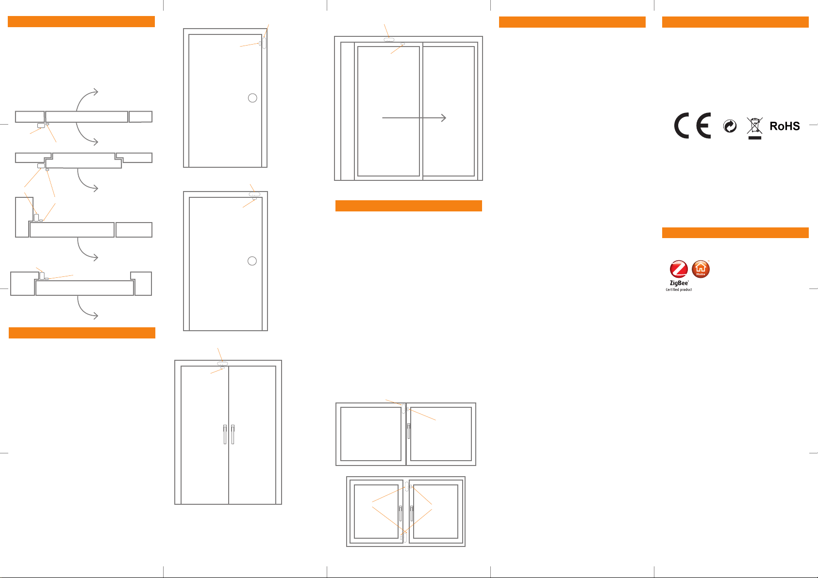
Placement Examples - Top View
• The most benecial distance between the
sensor and the magnet is 0.2-0.5 cm.
• Be aware that on magnetic surface (e.g.
metal door), the distance between the
sensor and the magnet has to be 0.1-0.3 cm.
Magnet (b)
Magnet (b)
Frame
Door
Sensor (a)
Window
Frame
Door
Window
Magnet (b)
Frame
Frame
Frame
Frame
Frame
Sensor (a)
Frame
Sensor (a)
Placement Examples - Doors
• Be sure to mount the sensor on the frame, to
protect the electronics from heavy vibrations.
• The sensor and magnet should be mounted
on the side opposite from the hinge/pivot
point.
• Pay careful attention to the arrow printed on
the sensor. This should be oriented to face
the magnet. The distance between the two
should not exceed 5mm.
Magnet (b)
Sensor (a)
Magnet (b)
Magnet (b)
Sensor (a)
Sensor (a)
Sensor (a)
Magnet (b)
Sliding Door
Placement Examples - Windows
• Be sure to mount the sensor on the frame, to
protect the electronics from heavy vibrations.
• The sensor and magnet should be mounted
on the side opposite from the hinge/pivot
point.
• Alternatively, if the window slides open, the
sensor and magnet may be mounted in
many positions, however the sensor should
always be placed on the frame.
• Pay careful attention to the arrow printed on
the sensor. This should be oriented to face
the magnet. The distance between the two
should not exceed 5mm.
Sensor (a)
Magnet (b)
Sensor (a)
Magnet (b)
FCC statement
FCC statement
Changes or modications to the equipment not
expressly approved by the party responsible for
compliance could void the user’s authority to
operate the equipment.
NOTE: This equipment has been tested and
found to comply with the limits for a Class
B digital device, pursuant to Part 15 of the
FCC Rules. These limits are designed to
provide reasonable protection against harmful
interference in a residential installation.
This equipment generates, uses and can
radiate radio frequency energy and, if not
installed and used in accordance with the
instructions, may cause harmful interference
to radio communications. However, there is no
guarantee that interference will not occur in a
particular installation.
If this equipment does cause harmful
interference to radio or television reception,
which can be determined by turning the
equipment o and on, the user is encouraged
to try to correct the interference by one or more
of the following measures:
• Reorient or relocate the receiving antenna.
• Increase the separation between the
equipment and receiver.
• Connect the equipment into an outlet on
a circuit dierent from that to which the
receiver is connected.
• Consult the dealer or an experienced radio/
TV technician for help.
This device complies with FCC RF radiation
exposure limits set forth for an uncontrolled
environment. The antenna used for this
transmitter must be installed to provide a
separation distance of at least 20 cm from
all persons and must not be co-located or
operating in conjunction with any other antenna
or transmitter.
This device complies with part 15 of the FCC
Rules. Operation is subject to the following two
conditions:
1. This device may not cause harmful interference, and
2. this device must accept any interference
received, including interference that may
cause undesired operation.
CE certication
The CE mark axed to this product conrms
its compliance with the European Directives
which apply to the product and, in particular, its
compliance with the harmonized standards
and specications.
IN ACCORDANCE WITH THE DIRECTIVES
• Radio equipment directive
2014/53/EU
• RoHS Directive 2011/65/EU
Other certications
• ZigBee Home Automation 1.2 certied.
Distributed by Develco Products A/S
Olof Palmes Allé 40
8200 Aarhus N
Denmark
All rights reserved.
Develco Products assumes no responsibility for
any errors, which may appear in this manual.
Furthermore, Develco Products reserves the
right to alter the hardware, software, and/
or specications detailed herein at any time
without notice, and Develco Products does
not make any commitment to update the
information contained herein. All the trademarks
listed herein are owned by their respective
owners.
Copyright © Develco Products A/S

Window Sensor - WISZB-120
Technical manual
Revised 20.12.2017

Window Sensor - WIS-120 – Technical manual
Develco Products A/S
Olof Palmes Allé 40
http://develcoproducts.com
DK-8200 Aarhus N
info@develcoproducts.com
Content
1 Cautionary notes ...................................................................................................................................................................................................................... 5
2 Features ........................................................................................................................................................................................................................................ 6
2.1 Window Sensor - WISZB-120 .................................................................................................................................................................................... 6
2.2 IAS Zone ................................................................................................................................................................................................................................... 6
2.3 Temperature ......................................................................................................................................................................................................................... 6
2.4 Key features .......................................................................................................................................................................................................................... 6
3 Endpoints....................................................................................................................................................................................................................................... 7
3.1 ZigBee Device Object (ZDO) ........................................................................................................................................................................................ 7
3.2 IAS Zone .................................................................................................................................................................................................................................... 7
3.3 Temperature Sensor ......................................................................................................................................................................................................... 7
3.4 Develco Utility ....................................................................................................................................................................................................................... 7
4 Supported Clusters................................................................................................................................................................................................................ 8
4.1 Common clusters for each end point .................................................................................................................................................................. 8
4.1.1 Basic – Cluster id 0x0000................................................................................................................................................................................... 8
4.1.1.1 Attribute ................................................................................................................................................................................................................... 8
4.1.2 Identify – Cluster id 0x0003 .............................................................................................................................................................................. 8
4.1.2.1 Attribute ................................................................................................................................................................................................................... 8
4.1.2.2 Commands ..............................................................................................................................................................................................................9
4.2 IAS Zone Device – EP 0x23 ...........................................................................................................................................................................................9
4.2.1 IAS Zone - Cluster id 0x0500 ............................................................................................................................................................................9
4.2.1.1 Attribute ....................................................................................................................................................................................................................9
4.2.1.2 Commands ........................................................................................................................................................................................................... 10
Note: How to clear a alarm in the “Zone status” ................................................................................................................................................. 11
4.2.2 Power Configuration - Cluster id 0x0001 ................................................................................................................................................ 11
4.2.2.1 Attribute .................................................................................................................................................................................................................. 11
4.2.3 Poll Control - Cluster id 0x0020 ....................................................................................................................................................................12
4.2.3.1 Attribute ..................................................................................................................................................................................................................12
4.2.4 OTA Upgrade – Cluster id 0x0019 ...............................................................................................................................................................12
4.2.4.1 Attributes ...............................................................................................................................................................................................................13
2

Window Sensor - WIS-120 – Technical manual
Develco Products A/S
Olof Palmes Allé 40
http://develcoproducts.com
DK-8200 Aarhus N
info@develcoproducts.com
4.2.4.2 Commands ............................................................................................................................................................................................................13
4.2.4.3 OTA Upgrade Messages Diagram ....................................................................................................................................................... 14
4.2.5 Time – Cluster id 0x000A ................................................................................................................................................................................. 15
4.2.5.1 Attribute ................................................................................................................................................................................................................. 15
4.2.6 Binary Input Cluster - Cluster id 0x000F ................................................................................................................................................ 15
4.2.6.1 Attribute ................................................................................................................................................................................................................. 15
4.3 Temperature Sensor Device – EP 0x26 ............................................................................................................................................................ 16
4.3.1 Temperature Measurement – Cluster id 0x0402 ............................................................................................................................. 16
4.3.1.1 Attribute ................................................................................................................................................................................................................. 16
5 MMI user guide ........................................................................................................................................................................................................................17
5.1 Push Button Menu ............................................................................................................................................................................................................17
5.1.1 EZ mode - Initiator ..................................................................................................................................................................................................17
5.1.2 EZ mode - Target ................................................................................................................................................................................................... 18
5.1.3 Factory reset ............................................................................................................................................................................................................. 18
5.2 Action on Power On ........................................................................................................................................................................................................ 18
6 General network behaviour ........................................................................................................................................................................................... 19
6.1 Installation ............................................................................................................................................................................................................................ 19
6.2 Normal – Keep alive ....................................................................................................................................................................................................... 19
6.2.1 Network lost .............................................................................................................................................................................................................. 19
6.3 Low battery .......................................................................................................................................................................................................................... 20
7 Specifications ...........................................................................................................................................................................................................................21
8 Contact Information ............................................................................................................................................................................................................ 22
3

Window Sensor - WIS-120 – Technical manual
Develco Products A/S
Olof Palmes Allé 40
http://develcoproducts.com
DK-8200 Aarhus N
info@develcoproducts.com
RoHS
Copyright © Develco Products A/S
All rights reserved.
Develco Products assumes no responsibility for any errors, which may appear in this manual. Furthermore,
Develco Products reserves the right to alter the hardware, software, and/or specifications detailed herein at any
time without notice, and Develco Products does not make any commitment to update the information contained
herein.
All the trademarks listed herein are owned by their respective owners.
4

Window Sensor - WIS-120 – Technical manual
Develco Products A/S
Olof Palmes Allé 40
http://develcoproducts.com
DK-8200 Aarhus N
info@develcoproducts.com
1 Cautionary notes
Develco Products A/S reserves the right to make changes to any product to improve reliability without further
notice. Develco Products A/S does not assume any liability arising out of the application or use of any product or
circuit described herein; neither does it convey any license under patent rights or the rights of third parties.
5

Window Sensor - WIS-120 – Technical manual
Develco Products A/S
Olof Palmes Allé 40
http://develcoproducts.com
DK-8200 Aarhus N
info@develcoproducts.com
2 Features
2.1 Window Sensor - WISZB-120
The Window Sensor enables you to detect whether windows or doors are closed or open. When the sensor part
and the magnet part is separated the alarm is activated. It protects your home and gives an alert when
unexpected action is occurred.
The Window Sensor also includes temperature measuring functionality. The sensor is battery powered and is
easily mounted by the included screws or double-stick tape.
The sensor has two ZigBee end points, one for the magnetic sensor and one for temperature.
2.2 IAS Zone
The Window Sensor is implemented as a IAS Zone ZigBee end point according to ZigBee Home Automation
profile „IAS Zone“.
2.3 Temperature
The temperature sensor measures temperature with a resolution of 0.1°C.
It supports standard ZigBee reporting (on change or interval).
The end point is configured as the Home Automation profile “Temperature Sensor“
2.4 Key features
Key features are:
Alarm sensor – IAS Zone
Temperature sensor
Binary input cluster
ZigBee OTA cluster for firmware upgrades
ZigBee HA 1.2 Certified application profile
ZigBee PRO is supported
RoHS compliant according to the EU Directive 2002/95/EC
Standard ZigBee Home Automation security and stack settings are used
6

Window Sensor - WIS-120 – Technical manual
Develco Products A/S
Olof Palmes Allé 40
http://develcoproducts.com
DK-8200 Aarhus N
info@develcoproducts.com
3 Endpoints
The device implements the following standard HA devices on different end points.
3.1 ZigBee Device Object (ZDO)
End point number 0x00
Application profile Id 0x0000
Application device Id 0x0000
Supports all mandatory clusters
3.2 IAS Zone
End point number 0x23
Application profile Id 0x0104 (Home Automation)
Application device Id 0x0402
3.3 Temperature Sensor
End point number 0x26
Application profile Id 0x0104 (Home Automation)
Application device Id 0x0302
3.4 Develco Utility
Application profile Id 0xC0C9 (Develco Products private profile)
Application device Id 0x0001
Manufactor code for Develco Products is 0x1015
Private profile for internal Develco Products use only.
Reference documents:
053474r18ZB_CSG-ZigBee-Specification.pdf
075123r03ZB_AFG-ZigBee_Cluster_Library_Specification.pdf
053520r27ZB_HA_PTG-Home-Automation-Profile.pdf
075356r15ZB_ZSE-ZSE-AMI_Profile_Specification.pdf
They can all be downloaded from :
http://www.zigbee.org/Products/DownloadZigBeeTechnicalDocuments.aspx
7

Window Sensor - WIS-120 – Technical manual
Develco Products A/S
Olof Palmes Allé 40
http://develcoproducts.com
DK-8200 Aarhus N
info@develcoproducts.com
4 Supported Clusters
Id#
Name
Type
Range
Man/Opt
Relevance and ref.
0x0
ZCLVersion
Uint8
Type range
M 0x4
ManufacturerName
String
0-32 byte
O
4.1.1.1.1
0x5
ModelIdentifier
String
0-32 byte
O
4.1.1.1.2
0x6
DateCode
String
0-32 byte
O
0x7
PowerSource
8 bit enum
Type range
M
Id#
Name
Type
Range
Man/Opt
Relevance and ref.
0x8000
PrimarySwVersion
OctetString
M SW version
Id#
Name
Type
Range
Man/Opt
Relevance and ref.
0x0000
IdentifyTime
Uint16
Type range
M
4.1 Common clusters for each end point
The ZCL “General Function Domain” clusters in this section are implemented as server clusters. Refer to ZigBee
Cluster Library Specification. http://www.zigbee.org/Specifications.aspx
4.1.1 Basic – Cluster id 0x0000
Only the first set has mandatory attributes, also the optional attributes that can be relevant to a Develco device
are all in set 0x000.
4.1.1.1 Attribute
4.1.1.1.1 ManufacturerName
“Develco Products A/S”
4.1.1.1.2 ModelIdentifier
“WISZB-120”
4.1.1.1.3 Manufacture Specific Attribute
ZCL header setting – Manufacture code for Develco Products is 0x1015
4.1.2 Identify – Cluster id 0x0003
4.1.2.1 Attribute
8

Window Sensor - WIS-120 – Technical manual
Develco Products A/S
Olof Palmes Allé 40
http://develcoproducts.com
DK-8200 Aarhus N
info@develcoproducts.com
4.1.2.2 Commands
Id#
Name
Payload
Man/Opt
Relevance and ref.
0x00
Identify
Uint16 - Identify Time (seconds)
M
0x00
0x01
Identify Query
none
M
0x01
Id#
Name
Payload
Man/Opt
Relevance and ref.
0x00
Identify Query Response
Uint16 - Identify Time (seconds)
M
0x00
Id#
Name
Type
Man/Opt
Relevance and ref.
0x0000
Zone State
8-bit
Enumeration
M 0x0001
Zone Type
16-bit
Enumeration
M
Hard coded to 0x0015
Contact Switch
0x0002
Zone Status
Uint16
M
The following bits are
supported:
Bit0: Alarm 1
Bit2: Tamper
Bit3: Battery
Bit4: Supervision reports
Bit5: Restore reports
0x0010
IAS CIE Address
Valid 64-bit
IEEE address
M
0x0011
ZoneID
Uint8
M
The identify cluster has 2 commands as server.
The identify cluster has 1 command as client.
4.2 IAS Zone Device – EP 0x23
4.2.1 IAS Zone - Cluster id 0x0500
The IAS Zone cluster is described in ZigBee Cluster Library Specification.
4.2.1.1 Attribute
4.2.1.1.1 Zone State
The device will automatically start to scan the network for an IAS Zone client in a predefine interval. When the
client is found it will automatically attempt to enrol. When it has successfully enrolled the Zone Status command
is send every 5 minutes.
9

Window Sensor - WIS-120 – Technical manual
Develco Products A/S
Olof Palmes Allé 40
http://develcoproducts.com
DK-8200 Aarhus N
info@develcoproducts.com
Id#
Name
Payload
Man/Opt
Relevance and ref.
0x00
Zone Status Change
Notification
Uint16 – bit mask
M
The status is report
to the coordinator
every 5 min
0x01
Zone Enroll Request
Bits
16
16
M
Data type
16 bit enum
UINT16
Field
name
Zone
type
Manufacturer
code
The attribute value will change from not enrolled (0x00) to Enrolled (0x01).
4.2.1.1.2 IAS CIE Address
Attribute specifies the address that commands generated by the server shall be sent to.
To un-enrol the device the back end system has to write a new address into this attribute. Any value is valid. If the
back end system writes an IEEE address then it will try to enrol to this devices represented by the IEEE address.
4.2.1.1.3 ZoneID
A unique reference number allocated by the CIE at zone enrolment time.
Used by IAS devices to reference specific zones when communicating with the CIE. The
stays fixed until that zone is un-enrolled.
ZoneID
of each zone
4.2.1.2 Commands
The IAS Zone cluster has 2 commands as server.
Init sequence – when the device has join the network it start to scan for an IAS zone client cluster. If a
client is found a Zone enroll request command is send and a Zone Enroll response is expected. If it
doesn’t receive a response within 15 sec it gives up and will continue to scan x number of attempts.
When the init sequence is over it will enter a state where it scans for a client every 12 hour.
The following bits are supported in Zone status:
Bit0: Alarm 1
Bit2: Tamper
Bit3: Battery
Bit4: Supervision reports
Bit5: Restore reports
10

Window Sensor - WIS-120 – Technical manual
Develco Products A/S
Olof Palmes Allé 40
http://develcoproducts.com
DK-8200 Aarhus N
info@develcoproducts.com
Bit0, Alarm
Id#
Name
Type
Range
Man/Opt
Relevance and ref.
0x0020
BatteryVoltage
Uint8
0x00 - 0xFF
O
ZCL configure reporting is
supported
0x0031
BatterySize
enum8
AAA
(0x04)
O
0x0033
BatteryQuantity
Uint8
2
O
0x0034
BatteryRatedVoltage
Uint8
O
Unit is in 100 mV
0x0036
BatteryVoltageMinThr
eshold
Uint8
25 Unit is in 100 mV
0x003E
BatteryAlarmState
Map32
O
Bit0:
BatteryVoltageMinThreshold
Is set if BatteryVoltage has
been below
BatteryVoltageMinThreshold
or other internal circuits has
deemed the supply to be
inadequate.
This bit will only reset after a
power cycle.
The condition will also be
shown on the MMI LED, see
MMI description.
Reportable. Default Min 12
hours, max 12 hours
Note: How to clear a alarm in the “Zone status”
The sensor requests ZCL Default Response on the Zone Status Change notification, if any new Alarm bit has been
set. Until the IAS CIE has acknowledged the received alarm by sending the mandated Default Response, the
Alarm bits are not cleared – even if there is no longer an alarm situation. When the Default Response is received, a
new Zone Status Change notification is sent with the Alarm bits cleared, if the alarm situation has disappeared
since sending the Zone Status message with alarm set.
Bit3: When the battery is below 2.2 VDC. Battery bit is set high and “Zone Status” is transmitted to the coordinator.
4.2.2 Power Configuration - Cluster id 0x0001
The power configuration cluster is described in ZigBee Cluster Library Specification
4.2.2.1 Attribute
11

Window Sensor - WIS-120 – Technical manual
Develco Products A/S
Olof Palmes Allé 40
http://develcoproducts.com
DK-8200 Aarhus N
info@develcoproducts.com
Id#
Name
Type
Range
Man/Opt
Relevance and ref.
0x0000
Check-inInterval
Uint32
0x00 - 0xFF
M
Default value is 1 hour
0x0001
LongPoll Interval
Uint32
M Default value is disabled
0x0002
ShortPollInterval
Uint16
M
Default value is 3
seconds
0x0003
FastPollTimeout
Uint16
M Default value is 5 minutes
Note: The attribute “BatteryVoltage” is measuring the battery voltage, in units of 100mV.
4.2.3 Poll Control - Cluster id 0x0020
The poll control cluster is described in ZigBee Cluster Library Specification
This cluster provides a mechanism for the management of an end device’s MAC Data Request rate. For the
purposes of this cluster, the term “poll” always refers to the sending of a MAC Data Request from the end device
to the end device’s parent.
This cluster can be used for instance by a configuration device to make an end device responsive for a certain
period of time so that the device can be managed by the controller.
4.2.3.1 Attribute
Start up, auto scan for client poll control cluster on the coordinator. If it is support on the coordinator an auto bind
is created and the smoke sensor will send a check-in command in the interval specified in attribute “Check-
inInterval. The coordinator has to reply with a check-in response. The sensor supports the following commands
send from the client (Typically the coordinator).
0x00 Check-in Response,
0x01 Fast Poll Stop,
0x02 Set Long Poll Interval,
0x03 Set Short Poll Interval,
If it doesn’t find a poll client it will search again periodically.
4.2.4 OTA Upgrade – Cluster id 0x0019
The cluster provides a ZigBee standard way to upgrade devices in the network via OTA messages. The devices
support the client side of the cluster.
12

Window Sensor - WIS-120 – Technical manual
Develco Products A/S
Olof Palmes Allé 40
http://develcoproducts.com
DK-8200 Aarhus N
info@develcoproducts.com
When the devices has joined a network it will automatically auto scan for a OTA upgrade server in the network. If it
Id#
Name
Type
Range
Man/Opt
Relevance and ref.
0x0000
UpgradeServerID
IEEE
Address
- M
0x0001
FileOffset
Uint32
Type range
O
0x0002
CurrentFileVersion
Uint32
Type range
O
0x0003
CurrentZigBeeStackVersion
Uint16
Type range
O
0x0004
DownloadedFileVersion
Uint32
Type range
O
0x0005
DownloadedZigBeeStackVersion
Uint16
Type range
M
0x0006
ImageUpgradeStatus
8 bit
enum
0x00 to 0xFF
O
0x0007
Manufacturer ID
Uint16
Type range
O
0x0008
Image Type ID
Uint16
Type range
O
0x0009
MinimumBlockRequestDelay
Uint16
Type range
O
Id#
Name
Man/Op
t
Relevance and ref.
0x01
Query Next Image request
M
6.10.1 OTA Cluster Command
Identifiers
0x03
Image Block Request
M
6.10.1 OTA Cluster Command
Identifiers
0x06
Upgrade End Request
M
6.10.1 OTA Cluster Command
Identifiers
finds a server an auto bind is created and ones every 24 hour it will automatically send its “current file version” to
the OTA upgrade server. It is the server that initiate the firmware upgrade process.
4.2.4.1 Attributes
Above attribute description is to be found in section 6.7 “OTA Cluster Attributes” in ZigBee document – “zigbee-
ota-upgrade-cluster-specification” provided by the ZigBee alliance.
4.2.4.2 Commands
The OTA Client cluster can send the following commands
13

Window Sensor - WIS-120 – Technical manual
Develco Products A/S
Olof Palmes Allé 40
http://develcoproducts.com
DK-8200 Aarhus N
info@develcoproducts.com
4.2.4.3 OTA Upgrade Messages Diagram
14

Window Sensor - WIS-120 – Technical manual
Develco Products A/S
Olof Palmes Allé 40
http://develcoproducts.com
DK-8200 Aarhus N
info@develcoproducts.com
4.2.5 Time – Cluster id 0x000A
Id#
Name
type
Range
Man/Opt
Relevance and ref.
0x0000
Time
UTCTime
(Uint32)
Type range
M
The module will
periodically update its
clock by synchronizing
through this cluster
0x0001
TimeStatus
8 bit bitmap
00000xxx
M
Id#
Name
Type
Range
Man/Opt
Relevance and ref.
0x001C
Description
String
Magnet open
O
0x0051
OutOfService
Bool
False (0) or
True (1)
M
If True, PresentValue will no
longer follow the physical
input, but will be writeable
0x0055
PresentValue
Bool
False (0) or
True (1)
M
Reflects the state of the
Magnet Open/Close alarm,
unless it is disabled by
setting the OutOfService
attribute to True.
Reportable. Default Min 1
sec, max 10 min
0x0067
Reliabillity
Enum8
O
0 – No Fault Detected
Reportable.
0x006F
StatusFlag
Map8
0x00-0x0F
M
Bit1: Fault. If set, the source
can be read in the Reliability
attribute
Reportable. Default Min 1
The Time cluster is a general cluster for time it is based on a UTC time in seconds since 0 hrs 0 mins 0 sec on 1st
January 2000. Refer to [Z2] for ZigBee specification of the time cluster.
The device will use this clusters as a client – provided that a suitable Time Server is available on the network
(most likely on the Gateway).
4.2.5.1 Attribute
4.2.6 Binary Input Cluster - Cluster id 0x000F
The Binary input cluster is described in ZigBee Cluster Library Specification
4.2.6.1 Attribute
15

Window Sensor - WIS-120 – Technical manual
Develco Products A/S
Olof Palmes Allé 40
http://develcoproducts.com
DK-8200 Aarhus N
info@develcoproducts.com
sec, max 10 min
Id#
Name
type
Range
Man/Opt
Relevance and ref.
0x0000
MeasuredValue
Sint16
MinValue to
MaxValue
M
ZCL Reporting is support
DP default is configured
0x0001
MinMeasuredValue
Sint16
0 M
0x0002
MaxMeasuredValue
Sint16
5000
M
4.3 Temperature Sensor Device – EP 0x26
The ZCL “Measurement and Sensing” cluster in this section is implemented as a server cluster. Refer to ZigBee
Cluster Library Specification.
4.3.1 Temperature Measurement – Cluster id 0x0402
The temperature measurement cluster is described in ZigBee Cluster Library Specification section 4.4.
4.3.1.1 Attribute
4.3.1.1.1 MeasuredValue
The attribute is configured with the following default “ZCL configure reporting” setting.
Min Reporting Interval: 0x003C [60 sec]
Max Reporting Interval: 0x0258 [600 sec]
Reportable Change: 0x000A [0.1 °C]
If the temperature value is stable it will be send every 10 minutes.
If the temperature changes more than 0.1 °C it will be reported but not faster than every 1 minute since last
reporting value.
Note: Min reporting interval 0 sec is invalid when reportable change is configured.
4.3.1.1.2 MinMeasuredValue
The temperature sensor is NOT supporting temperature measurements below 0 degrees Celsius.
4.3.1.1.3 MaxMeasuredValue
The temperature sensor is NOT supporting temperature measurements above 50 degrees Celsius.
16

Window Sensor - WIS-120 – Technical manual
Develco Products A/S
Olof Palmes Allé 40
http://develcoproducts.com
DK-8200 Aarhus N
info@develcoproducts.com
5 MMI user guide
Idle
EZ mode
Initiator
EZ mode
Target
Factory reset
Push + Hold button
untill led blinks once
Push + Hold button
untill led blinks
continously
Push + Hold button
untill led blinks
twice
Push + Hold button
untill led is off
5.1 Push Button Menu
Pushing the button on a device provides the user with several possibilities.
Pushing the button for longer (push, hold for a few seconds, and release) allows the user to set the device into a
desired mode. A mode change happens at 5 second interval. Below, these modes are illustrated in a state chart.
When cycling through the menu modes, the state is indicated by a number of 100ms blinks on the LED. The
device is supporting the ZigBee standardized EZ- mode Commissioning.
5.1.1 EZ mode - Initiator
If the devices is not on the network EZ-Mode Network Steering is invoked when the user enter this menu. The led
blinks once every 1 sec until the devices has joined the network. If the device was already on the network it will
broadcast the PermitJoin messages. It is the trust center policy that decides if the device is allowed to join the
network.
When the device has joined the network EZ-Mode Finding and Binding is invoked and the device start to blink
every 3 sec until a cluster match is found. When a match is found or the cluster examine is finished the blinking
stops and the device sends a messages to the target device to stop the identify time.
The following clusters are support in EZ-mode finding and binding:
Temperature cluster
Power configuration cluster
17

Window Sensor - WIS-120 – Technical manual
Develco Products A/S
Olof Palmes Allé 40
http://develcoproducts.com
DK-8200 Aarhus N
info@develcoproducts.com
The EZ-mode time is hard coded to 3 minutes. This is the Minimum and recommended PermitJoin time broadcast
for EZ-Mode Network Steering and minimum IdentifyTime set for EZ-Mode Finding and Binding. If the user enters
the menu again another 3 minutes is started.
5.1.2 EZ mode - Target
If the devices is not on the network EZ-Mode Network Steering is invoked when the user enter this menu. The led
blinks twice every 1 sec until the devices has joined the network. If the device was already on the network it will
broadcast the PermitJoin messages. It is the trust center policy that decides if the device is allowed to join the
network.
When the device has joined the network identify mode is invoke and the device start to blink twice every 3 sec
until identify mode is stopped or after the EZ-mode time has expired. If the user enters the menu again another 3
minutes is started.
5.1.3 Factory reset
To allow a device to join a network, one either has to power up a device that has not previously joined a network
or push the button until the Reset To Factory default mode is indicated – and subsequently release the button.
This will cause the device to reset to its factory default state and scan for a suitable coordinator.
5.2 Action on Power On
As a general rule, all end devices and routers that have not previously joined a network (or have been reset to
factory default) will start up and search for a network with join permit open. In this mode, the LED will flash once
every second.
Once the device has joined the network, is will start scanning for an OTA server, Time server, Poll control client
and an IAS Zone client.
If a device has joined a network and is powered down, it will attempt to rejoin this network upon power up. For the
first 30 seconds hereafter, the device will be available for communication. This time can be expanded using the
poll control cluster functionality.
18

Window Sensor - WIS-120 – Technical manual
Develco Products A/S
Olof Palmes Allé 40
http://develcoproducts.com
DK-8200 Aarhus N
info@develcoproducts.com
6 General network behaviour
#Scan mode - 1
Scan all 16 ZigBee
channel until join
network or 15
minutes
#Sleep mode
MCU is in sleep
mode (Radio off)
15 minutes
#Scan mode - 2
Scan all 16 ZigBee
ch x 4 or until join
network
~ 30 seconds
#Sleep mode
MCU is in sleep
mode (Radio off)
15 minutes
#Scan mode - 2
Scan all 16 ZigBee
ch x 4 or until join
network
~ 30 seconds
6.1 Installation
When the device is virgin and powered for the first time it will start looking for a ZigBee PAN Coordinator or router
to join. The device will scan each ZigBee channel starting from 11 to 24. The LED will flash once every second until
it joins a device.
The device will start up using scan mode 1. To increase battery lifetime when the device is joining a network for
the first time a scan mode 2 will be used after scan mode 1 has expired. Scan mode 1 it will only be executed one
time when the device is powered. If the user invokes EZ-mode it will start scanning the next 3 minutes
In section 5 “MMI” it is explained how to put the device into a join or leave network mode.
Network settings are stored in NV-memory are after a power cycle the device re-join the same network.
If the device has to join a new PAN coordinator the MMI menu supports a “Reset To Factory Fresh Settings” mode.
This will erase all current network information.
6.2 Normal – Keep alive
The device is sending a “keep alive” message to the PAN coordinator every 15 minute to verify that the device is
still connected to the network.
6.2.1 Network lost
If no “keep alive” responses are received 5 times in a row (Worst case 1h15m), the devices will start scanning as
specified in the table below.
When the device is in scan mode the LED will flash once every second until it re-joins the network.
According to the ZigBee specification TX is NOT allowed to be enabled all the time and a TX silent period has to
be defined.
19

Window Sensor - WIS-120 – Technical manual
Develco Products A/S
Olof Palmes Allé 40
http://develcoproducts.com
DK-8200 Aarhus N
info@develcoproducts.com
#Scan mode - 1
Scan current ch 3
times
Scan remaining 15
ch 1 time
Scan all 16 ch 3
times
#Sleep mode
MCU is in sleep
mode (Radio off)
15 minutes
#Scan mode - 2
Scan current ch 3
times
Scan remaining 15
ch 1 time
#Sleep mode
MCU is in sleep
mode (Radio off)
15 minutes
#Scan mode - 2
Scan current ch 3
times
Scan remaining 15
ch 1 time
6.3 Low battery
The current battery voltage can be read from the power configuration cluster described in section 4.3.1. The
attribute “BatteryVoltage” is measuring the battery voltage, in units of 100mV.
Low batt LED indication – RED LED will blink twice every 60 second
20

Window Sensor - WIS-120 – Technical manual
Develco Products A/S
Olof Palmes Allé 40
http://develcoproducts.com
DK-8200 Aarhus N
info@develcoproducts.com
7 Specifications
General
Dimensions (L x B x H)
76 x 25 x 17 mm (Sensor part)
30 x 12 x 9 (magnet part)
Colour
White and light grey
Battery
Battery: 2 x AAA, exchangeable
Battery life
Battery life:
HW version x < 2.0.0, up to 6 years, 2 minutes reporting
HW version x >= 2.0.0, up to 9 years, 2 minutes reporting
Radio
Sensitivity: -98 dBm
Output power: +6 dBm (EU)
Environment
IP class: IP40
Operation temperature 0 to +50°C
Function
Temperature sensor
Range: 0 to +50°C
Resolution: 0.1°C (accuracy ± 0.5°C)
Sample time: config.: 2 s -65.000 s
Reporting: configurable
Detection
Magnetic: 0.1-1.0 cm
Communication
Wireless protocol
ZigBee Home Automation compliant
ZigBee end-device
Certifications
RoHS compliant according to the EU Directive 2002/95/EC
21

Window Sensor - WIS-120 – Technical manual
Develco Products A/S
Olof Palmes Allé 40
http://develcoproducts.com
DK-8200 Aarhus N
info@develcoproducts.com
8 Contact Information
Technical support: Please contact Develco Products for support.
products@develcoproducts.com
Sales: Please contact Develco Products for information on prices, availability, and lead
time.
info@develcoproducts.com
22
 Loading...