

Develco MOSZB140 User Manual
eng
Motion Sensor Mini
INSTALLATION MANUAL
Version 1.1
• Place the sensor free of curtains and other
obstacles.
• Avoid placing the Motion Sensor Mini close
to a heating/cooling source.
• Avoid placing the Motion Sensor Mini in
direct sunlight or bright light.
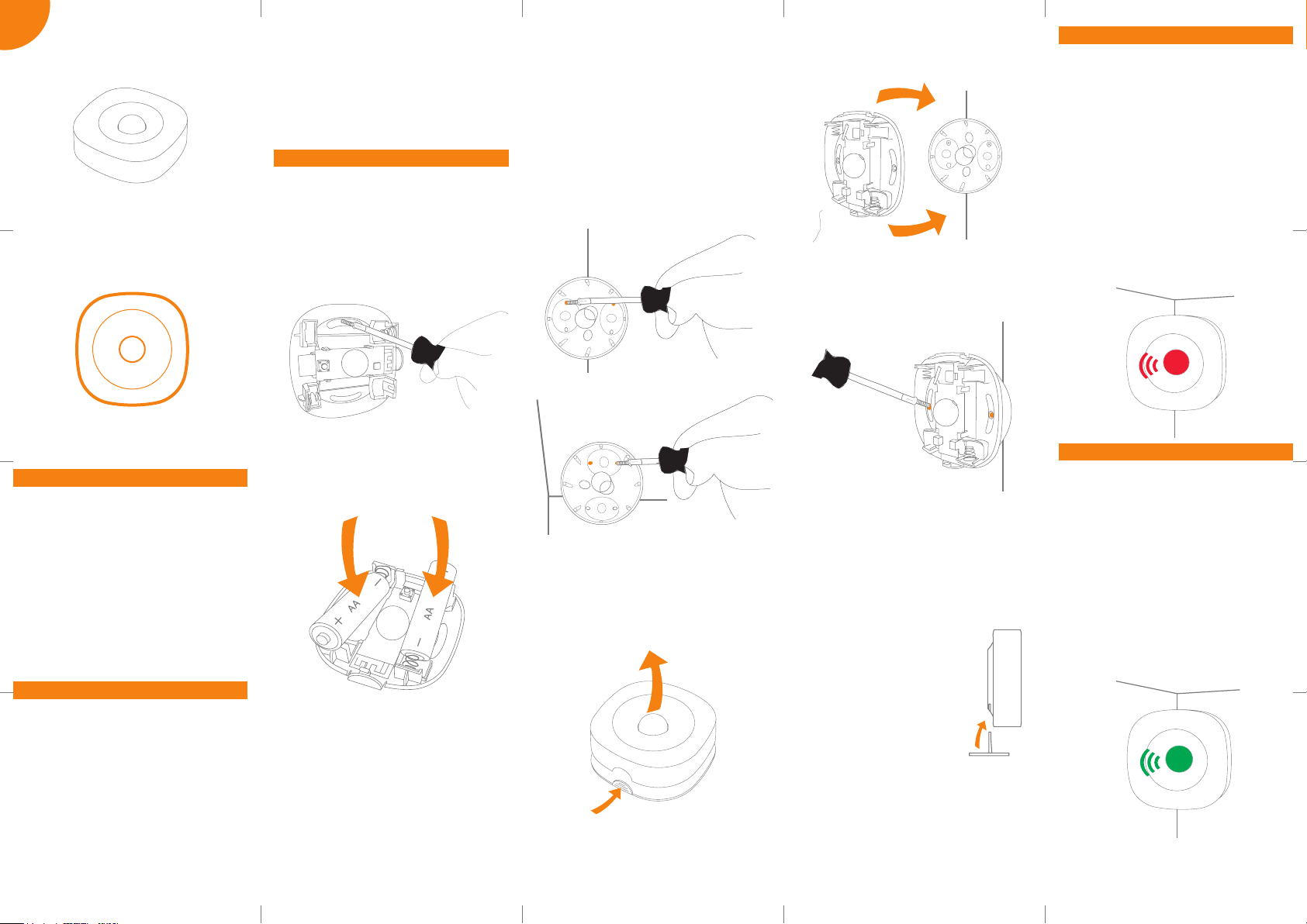
Mounting
MOUNTING FLAT ON CEILING OR WALL
1. Open the casing, and use the sensor part
with oval holes to mark the screw holes on
a ceiling or a wall.
2. Mount the sensor on the wall or the ceiling
by installing one screw from the bag
marked “A” through each oval hole.
a.
CORNER OR CEILING MOUNTING WITH
BRACKET
1. If you have a sensor with a bracket included,
you can mount the sensor with this bracket
in a corner or on the ceiling.
2. Use the bracket to mark the screw holes on
the two walls in the corner of the room or
on the ceiling.
3. Use the two screws in the bag marked “A”
to install the bracket in the marked place.
c.
6. Place the part with oval holes against the
already mounted bracket.
e.
7. Take two screws from the bag marked “B”.
Mount one screw through each oval hole
and into two holes on the bracket.
f.
Connecting
1. When batteries are inserted, the Motion
Sensor Mini will automatically start
searching (up to 15 minutes) for a Zigbee
network to join.
2. Make sure that the Zigbee network is open
for joining devices and will accept the
Motion Sensor Mini.
3. While the sensor is searching for a Zigbee
network to join, the LED ashes red.
4. When the sensor is connected to a network,
it wil stop ashing.
h.
Product description
The compact Motion Sensor Mini allows the
user to detect occupancy. With the Motion
Sensor Mini, the user can set the light to
turn on and o as people come and go. The
motion sensor is PIR based and is able to
sense movement up to 9 meters from the
sensor.
Motion Sensor Mini includes two logical
outputs – one with high sensitivity for
occupancy and one with a lower sensitivity
for alarm.
Placement
• Place the sensor indoors at a temperature
between 0-50°C.
• Its angle of detection from above, the sides,
and below must be 45°.
• Place the Motion Sensor Mini in a location
with a clear view of the monitored area and
the windows.
• The distance from the sensor to a replace
or a stove must be at least four meters.
• The Motion Sensor Mini must be reachable
for battery testing and maintenance.
3. Alternatively, you can use the adhesive
tape from bag “A” to mount the sensor.
4. Insert batteries and make sure that the
batter y polarity is correct (+/-).
b.
5. Close the casing of the sensor.
4. Alternatively, you can use the adhesive
tape from bag “A” to mount the bracket.
5. Open the casing of the sensor.
d.
8. Insert batteries and make sure that the
battery polarity is correct (+/-).
9. Close the casing of the sensor.
STAND
1. If you have a sensor with
a plastic stand included,
you can insert the stand
in the opening on the
back of the sensor as
shown on the drawing.
2. Place the standing sensor
on the shelf or on a desk.
g.
Modes
SEARCHING GATEWAY MODE
Red LED light is ashing every second (up to
15 minutes).
ALARM TESTING MODE
The motion sensor will automatically ash
green every time movement is detected by
the Intruder Alarm System (IAS), no matter if
the alarm system is activated or deactivated.
The green ashes can help you determine
if the placement of the sensor is suitable for
alarm purposes.
i.
LOW BATTERY MODE
The device will ash red twice every minut
when the battery is low.
Quelle: http://www.barcode-generator.de
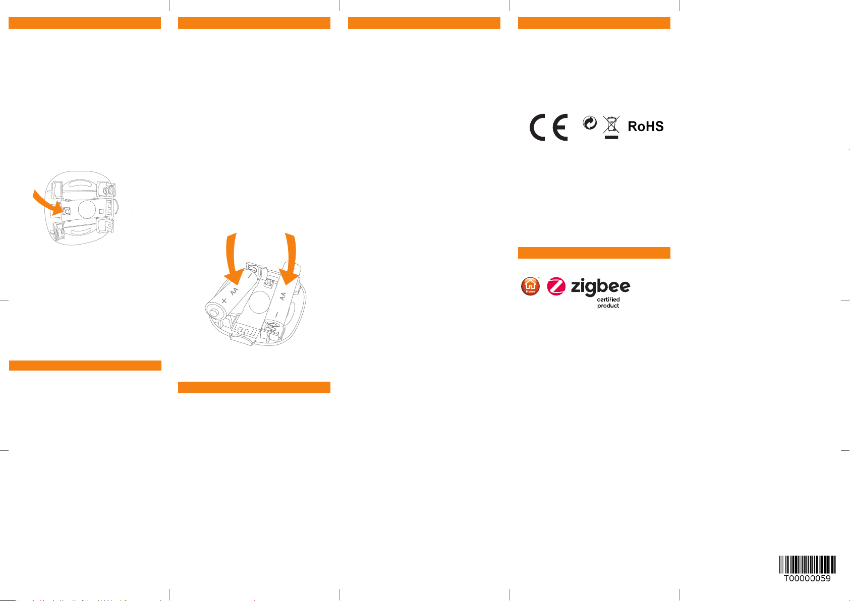
Resetting
Resetting is needed if you want to connect
your Motion Sensor Mini to another gateway,
or if you need to perform a factory reset to
eliminate abnormal behaviour.
STEPS FOR RESETTING
1. Detach the sensor from the bracket and/or
open the casing.
2. Check that the battery is inserted correctly.
3. Press and hold the round menu button
inside the device.
j.
4. While you are holding the button down, the
LED rst ashes once, then two times in a
row, and nally numerous times in a row.
5. Release the button while the LED is ashing
numerous times in a row.
6. After you release the button, the LED shows
one long ash, and the reset is completed.
Fault nding
• In case of a bad or weak signal, change
the location of the Motion Sensor Mini.
Otherwise, you can relocate your gateway
or strengthen the signal with a smart plug.
• If the search for a gateway has timed out, a
short press on the button will restart it.
Battery replacement
The device will blink twice every minute when
the battery is low.
CAUTION: RISK OF EXPLOSION IF BATTERIES
ARE REPLACED BY AN INCORRECT
TYPE. DISPOSE OF THE BATTERIES IN
ACCORDANCE WITH INSTRUCTIONS.
CAUTION: When removing cover for battery
change - Electrostatic Discharge (ESD) can
harm electronic components inside
1. To replace the battery, detach the Motion
Sensor Mini from the bracket and/or open
the casing.
2. Replace the battery respecting the
polarities.
k.
3. Close the casing of the sensor.
Disposal
Dispose the product and battery properly at the
end of their lives. This is electronic waste, which
should be recycled.
FCC statement
FCC statement
Changes or modications to the equipment
not expressly approved by the party
responsible for compliance could void the
user’s authority to operate the equipment.
NOTE: This equipment has been tested and
found to comply with the limits for a Class B
digital device, pursuant to Part 15 of the FCC
Rules. These limits are designed to provide
reasonable protection against harmful
interference in a residential installation.
This equipment generates, uses and can
radiate radio frequency energy and, if not
installed and used in accordance with the
instructions, may cause harmful interference
to radio communications. However, there is no
guarantee that interference will not occur in a
particular installation.
If this equipment does cause harmful
interference to radio or television reception,
which can be determined by turning the
equipment o and on, the user is encouraged
to try to correct the interference by one or
more of the following measures:
• Reorient or relocate the receiving antenna.
• Increase the separation between the
equipment and receiver.
• Connect the equipment into an outlet on
a circuit dierent from that to which the
receiver is connected.
• Consult the dealer or an experienced
radio/TV technician for help.
This device complies with FCC RF radiation
exposure limits set forth for an uncontrolled
environment. The antenna used for this
transmitter must be installed to provide a
separation distance of at least 20 cm from
all persons and must not be co-located
or operating in conjunction with any other
antenna or transmitter.
This device complies with part 15 of the FCC
Rules. Operation is subject to the following
two conditions:
1. This device may not cause harmful interference, and
2. This device must accept any interference
received, including interference that may
cause undesired operation.
CE certication
The CE mark axed to this product conrms
its compliance with the European Directives
which apply to the product and, in particular,
its compliance with the harmonized standards
and specications.
IN ACCORDANCE WITH THE DIRECTIVES
• Radio Equipment Directive (RED)
2014/53/EU
• EMC Directive 2014/30/EU
• RoHS Directive 2015/863/EU amending
2011/65/EU
• REACH 1907/2006/EU + 2016/1688
Other certications
• Zigbee Home Automation 1.2 certied.
All rights reserved.
Develco Products assumes no responsibility
for any errors, which may appear in this manual.
Furthermore, Develco Products reserves
the right to alter the hardware, software,
and/or specications detailed herein at any
time without notice, and Develco Products
does not make any commitment to update
the information contained herein. All the
trademarks listed herein are owned by their
respective owners.
Distributed by Develco Products A/S
Tangen 6
8200 Aarhus N
Denmark
www.develcoproducts.com
 Loading...