

Page 1

MAINTENANCE AND OPERATION
INSTRUCTION MANUAL
Publish Date: 07-Jun-2016
DB6400
Advanced FM and Digital Radio
4-Band Audio Processor
with Backup Audio Player
Page 2

Contents
Introduction ........................................................................................................................................ 6
Typographic conventions .................................................................................................................. 7
General Information .......................................................................................................................... 8
Product Features ................................................................................................................................ 9
Technical Specications ................................................................................................................ 10
Front Panel ....................................................................................................................................... 12
OLED Display ............................................................................................................................... 12
LED Meters ................................................................................................................................... 12
Context-sensitive Soft Buttons ....................................................................................................... 12
Navigational Buttons ..................................................................................................................... 12
Rear Panel ..................................................................................................................................... 13
Rear Panel Alarm Terminal .......................................................................................................... 14
GPI Trigger Input Pins ............................................................................................................. 14
Digital I/O Pins ........................................................................................................................ 14
Before you start ................................................................................................................................ 15
Safety warning ............................................................................................................................... 15
Operating recommendations ......................................................................................................... 16
Unpacking and inspection ............................................................................................................. 17
Radio Frequency Interference (RFI) ............................................................................................. 17
Mounting ........................................................................................................................................... 18
Rack requirements ......................................................................................................................... 18
Heat Dissipation ............................................................................................................................ 18
AC Mains Power .............................................................................................................................. 19
Fuse holder .................................................................................................................................... 19
Mains Voltage Selector .................................................................................................................. 19
Power cord .................................................................................................................................... 19
Ground Loops ................................................................................................................................ 19
DB6400 Location .............................................................................................................................. 20
Source Material Quality .................................................................................................................. 20
Operation .......................................................................................................................................... 21
Processing path ............................................................................................................................. 21
Audio Processing Explained ......................................................................................................... 22
Basic Setup/Connection Example ................................................................................................... 23
Referencing Analog and Digital Inputs level ................................................................................ 23
Referencing Analog and Digital Outputs level .............................................................................. 24
Setup with Analog Program Inputs ............................................................................................... 25
Setup with Digital Program Inputs ............................................................................................... 26
Analog connection with two transmitters ...................................................................................... 27
Analog connection with DEVA SmartGen 6.0 ............................................................................... 28
Side-chain ................................................................................................................................. 28
Loop through ............................................................................................................................ 29
OLED Display, Navigational & Soft Buttons ................................................................................ 30
OLED Display ............................................................................................................................... 30
Header area .............................................................................................................................. 30
Main Screen working area ........................................................................................................ 31
Page 3

Soft Buttons ............................................................................................................................... 31
Navigation Buttons ................................................................................................................... 31
Menu Pages .............................................................................................................................. 32
[Input] .................................................................................................................................. 32
[Process] .............................................................................................................................. 32
[Output] ............................................................................................................................... 32
[Presets] ............................................................................................................................... 32
Settings .............................................................................................................................................. 38
Trigger ports .................................................................................................................................. 38
Keyboard lock................................................................................................................................ 39
Keyboard unlock ........................................................................................................................... 39
RDS ............................................................................................................................................... 40
Dayparting .................................................................................................................................... 40
Other sections ................................................................................................................................... 41
Stereo ............................................................................................................................................. 41
Status ............................................................................................................................................. 41
Factory and User presets ................................................................................................................. 42
Factory Presets.............................................................................................................................. 42
How to create and save a User Preset or How to customize your sound ................................. 42
WEB Interface .................................................................................................................................. 44
Manual IP Address Identication .................................................................................................. 44
Network Discovery ........................................................................................................................ 45
Access ............................................................................................................................................ 45
Status ............................................................................................................................................. 46
Settings .......................................................................................................................................... 47
General ..................................................................................................................................... 47
Communication......................................................................................................................... 48
Network ............................................................................................................................... 48
SNMP Agent ........................................................................................................................ 48
E-mail .................................................................................................................................. 48
HTTP Server ....................................................................................................................... 49
FTP Server .......................................................................................................................... 49
Syslog .................................................................................................................................. 49
Dayparts ................................................................................................................................... 50
Other ......................................................................................................................................... 51
Firmware Update ................................................................................................................ 51
Storage ................................................................................................................................ 51
System Log .......................................................................................................................... 51
Factory Defaults ................................................................................................................. 51
Reboot ................................................................................................................................. 51
Log ............................................................................................................................................ 52
Presets ........................................................................................................................................... 53
How can a user preset be made? .............................................................................................. 53
Preset Lock ............................................................................................................................... 54
Presets Export ........................................................................................................................... 54
Presets Import ........................................................................................................................... 55
Presets Delete ........................................................................................................................... 55
Input .............................................................................................................................................. 56
Page 4

AGC ............................................................................................................................................... 58
Equalizer ....................................................................................................................................... 59
Enhancer ....................................................................................................................................... 60
Multiband 1 (Multiband Limiter) .................................................................................................. 61
Multiband 2 (Multiband Limiter) .................................................................................................. 63
Final Limiter ................................................................................................................................. 64
MPX ............................................................................................................................................... 65
RDS Data ...................................................................................................................................... 66
Basic RDS ................................................................................................................................. 66
Output ............................................................................................................................................ 68
WARRANTY TERMS AND CONDITIONS ................................................................................. 69
Product Registration Card .............................................................................................................. 70
APPENDIX A ...................................................................................................................................71
RDS: Europe vs America .............................................................................................................. 71
The RDS System ........................................................................................................................... 71
APPENDIX B ................................................................................................................................... 72
How should I congure the connection between my DEVA Device and an FTP Client? 72
1. FTP Server Settings ......................................................................................................... 72
2. IP Router and Port Translation Settings .......................................................................... 72
3. Example of FTP Client (FileZilla) Settings .................................................................... 73
APPENDIX C.1 ................................................................................................................................ 74
PTY Code Description Used in RBDS Mode – North America ..................................................... 74
APPENDIX C.2 ................................................................................................................................ 75
PTY Code Description Used in RDS Mode – Europe, Asia .......................................................... 75
Page 5

THIS PAGE
IS INTENTIONALLY
LEFT BLANK
Page 6

65 Aleksandar Stamboliyski Str., 8000 Bourgas, Bulgaria
Tel: +359 56 820027, Fax: +359 56 836700
E-mail: ofce@devabroadcast.com ,Web: www.devabroadcast.com
- 6 -
Introduction
DEVA Broadcast Ltd. is an international communications and high-technology manufacturing
organization, its corporate headquarters and facility located in Burgas, Bulgaria. The company
serves the broadcast and corporate markets worldwide – from consumers and small businesses to
the largest global organizations. It is dedicated to the research, design, development and provision
of advanced products, systems and services. DEVA launched its own brand back in 1997 and has
nowadays evolved to become known as a market leader and internationally reputed manufacturer
of user-friendly, cost-effective and innovative broadcast products.
Creativity and innovation are deeply woven into DEVA corporate culture. Through successful
engineering, marketing and management our team of dedicated professionals creates futureoriented solutions to improve customers’ performance. You may rely that all issues communicated
to our crew would be addressed accordingly. We pride ourselves on our pre and post-sales support
and purchase services, which along with the outstanding quality of our radio gear have won us due
respect and the market authority position.
DEVA best-of-breed solutions have become the best sellers for our partners. The strategic
partnerships which have been formed with industry leaders during all these years that we have been
operating on the broadcasting market, have proved us a reliable business partner and a valuable
asset, as our dealers worldwide would conrm. In constant pursuit of precision and long-term
satisfaction, DEVA enhances the reputation of our partners and clients alike. Furthermore, we have
already a proven merit as a credible partner provider.
Our portfolio offers complete line of high quality and competitive products for FM and Digital
Radio, Radio Networks, Telecommunication Operators and regulation authorities. For almost
two decades of intensive software and hardware development, we have achieved a unique priceperformance and endurance of our product lines. Our company’s multitude of equipment and
services is in line with the latest technologies and key trends. The most recognizable characteristics
attributed to DEVA products are their clear-cut, streamlined design, easiness of use and costeffectiveness: simplicity of forms but multiplicity of functions.
For us there is no stage when we deem that we have reached the most satisfactory level in our
work. Our engineers are in constant pursuit of new ideas and technologies to be captured in DEVA
solutions. Simultaneously, a strict control is being exercised at each step of any new development.
Experience and hard work are our fundament but the continuous improving process is what we
never leave aside. DEVA participates on a regular basis in all landmark broadcasting events, not
only to promote its products, but to exchange valuable know-how and experience. We are also
engaged in international large-scale projects involving radio and audio solutions which makes us
even more competitive on the global market.
All DEVA products are developed and produced in accordance with the latest ISO 9001 quality
control standards.
Page 7

65 Aleksandar Stamboliyski Str., 8000 Bourgas, Bulgaria
Tel: +359 56 820027, Fax: +359 56 836700
E-mail: ofce@devabroadcast.com ,Web: www.devabroadcast.com
- 7 -
Typographic conventions
This manual uses the following typographic conventions:
Style Used for
NOTE
Important notes and recommendations
Example
Used when example text is cited
0 dB
Menu element value
“Menu” on page XX. References
[OK] Front panel navigation and soft buttons.
WEB Interface interactive buttons.
Settings
Menu element and soft button name. Menu path are represented as
follows: Settings> Security> Front Panel> Access control
Page 8

65 Aleksandar Stamboliyski Str., 8000 Bourgas, Bulgaria
Tel: +359 56 820027, Fax: +359 56 836700
E-mail: ofce@devabroadcast.com ,Web: www.devabroadcast.com
- 8 -
General Information
The long years of experience at the top level of broadcasting technologies, as well as the
undisputable expertise of our engineering team have brought forth a brand new audio processing
tool - the DB6400 FM and Digital Radio 4-Band Audio Processor.
The DSP-based Stereo Encoder guarantees precision of the MPX signal with advanced peak
control and two independently-congurable composite MPX outputs. The DB6400 offers perfect
audio clarity no matter what the source material is. A complete processing architecture: Wide
band AGC with “Intelligent Gating”, 4-band Parametric EQ, Advanced Bass and Treble Controls,
4-Band High Quality Sound processor with Fidelity control and Sound Impact, 4-Band Limiter,
FM Limiter with advanced distortion & pre-emphasis control and HD Lookahead Limiter.
Another feature that distinguishes the DB6400 from other products of its category is its Fallback
function. This cutting-edge device is able to detect signal loss. In the case of silence at the main
audio input, it automatically switches over to a backup source, thus ensuring a constant audio feed.
What is more, an e-mail notication is immediately sent which allows for an instant response on
the part of your technical support team. Through the use of a standard FTP client, you have the
opportunity to update the backup content at will via any PC. An additional asset is the automatic
return to the main audio source as soon as the default input is restored. All silence sense parameters
are user-dened.
Needless to say, the DB6400 comes with a user-friendly, comprehensive and well-organized
user interface. Access is available through the front panel, remotely via TCP/IP and by using the
WEB interface through iOS, Android or any other mobile device.
This one-of-a-kind device is the peak of DEVA’s engineering achievements combining simplicity
of use, affordability of price and top performance and employing an array of technical parameters
not found in any other device of its class.
Page 9

65 Aleksandar Stamboliyski Str., 8000 Bourgas, Bulgaria
Tel: +359 56 820027, Fax: +359 56 836700
E-mail: ofce@devabroadcast.com ,Web: www.devabroadcast.com
- 9 -
Product Features
• Ultra low latency, all-digital DSP based design
• Advanced Wide Band AGC
• 4-Band Parametric EQ
• Advanced Bass & Treble Controls
• 4-Band Limiter
• FM Controlled distortion Limiter
• 4-Band Dynamic Processor with Fidelity and Sound Impact System
• HD Lookahead Limiter
• Extensive set of factory presets and several customizable user presets
• L/R Analog inputs and outputs and two independent Composite MPX outputs.
• Integrated digital stereo generator with advanced peak control
• Built-in web server for remote control access via TCP/IP connection
• Software Control (over local network or the Internet using any Windows® PC)
• Built in DSP-based RDS/RBDS encoder
• Bright, wide view angle OLED and full-time LED meters
• Easy setup and control via the front panel
• Remotely upgradable rmware to ensure improved operation
• Headphone output with front panel level control
• Externally synchronized output sample rate
• Tight peak control at all outputs
• EMI-suppressed XLR connectors
• Stereo encoder integrated with audio processing
• Bypass and Test tone Mode
• Embedded SNMP agent permitting full device management
• Easy to use WEB interface
• Apple and Android devices support
• SNTP for automatic synchronization of the built-in clock
• Notications on input/preset change via E-mail and SNMP
• Protected access to the device settings
• Professional AES/EBU, SPDIF and Optical Digital audio inputs
• Level Adjustable, Balanced Analog and Digital Audio Outputs
• LAN port for full TCP/IP remote control and monitoring
• USB communication interface for local connectivity
• Easy Installation and Setup
• Wide operating voltage range: 100-240V AC
• 19” Professional Case for high RF immunity
Page 10

65 Aleksandar Stamboliyski Str., 8000 Bourgas, Bulgaria
Tel: +359 56 820027, Fax: +359 56 836700
E-mail: ofce@devabroadcast.com ,Web: www.devabroadcast.com
- 10 -
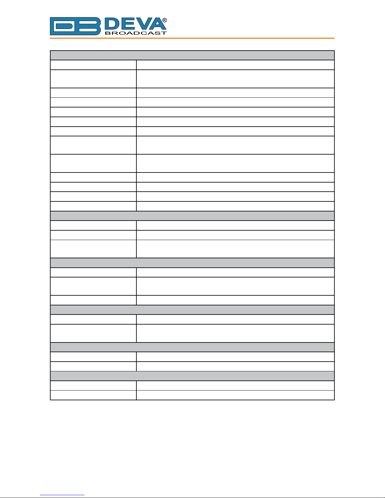
TECHNICAL SPECIFICATIONS
ANALOG AUDIO INPUT
Connectors Main - Two XLR, EMI suppressed, electronically balanced; Auxiliary
- DB9, EMI suppressed, electronically balanced
Conguration Stereo
Input level (0 dBFS) Software selectable -8 dBu to +24 dBu peak
Impedance Jumper selectable 600Ω / >10kΩ
A/D Conversion 24 bit; 48 kHz sample rate; Differential inputs
ANALOG AUDIO OUTPUT
Connectors Two XLR, EMI suppressed, electronically balanced
Conguration Stereo. Software selectable at, pre-emphasized or de-emphasized
Output Level (0 dBFS) Software selectable -12 dBu to +24 dBu peak into >= 600Ω load
Source Impedance 20Ω
Load Impedance >= 600Ω, balanced/unbalanced
Signal-to-Noise >= 110 dB unweighted (Bypass mode, digital input, at, 20Hz-
15kHz bandwidth, referenced to +12 dBu output level)
Distortion <= 0.01 THDN (Bypass mode, digital input, at, 20Hz-15kHz
bandwidth, referenced to +12 dBu output level)
D/A Conversion 24 bit; 192 kHz sample rate; Differential outputs
DIGITAL AUDIO INPUT
Connectors Main - XLR, EMI suppressed, transformer balanced and oating;
110Ω impedance; Auxiliary - DB9, EMI suppressed, transformer
balanced and oating; 110Ω impedance
Conguration Stereo AES3 standard, up to 24 bit resolution
Sampling Rate 22 kHz to 192 kHz
Input Gain -20 dB to 20 dB, referenced to 0 dBFS, software selectable
DIGITAL AUDIO OUTPUT
Connector XLR, EMI suppressed, transformer balanced and oating; 110Ω
impedance
Conguration Stereo AES3 standard, 24 bit resolution. Software selectable at,
pre-emphasized or de-emphasized
Sample Rate Internal - 32, 44.1, 48, 88.2, 96, 176.4, 192 kHz. Externally synced
to Main AES3 digital input at 32 to 192 kHz. Software selectable.
Word Length 24 bit
Output Reference Level -20 to 0 dBFS software selectable
Page 11
65 Aleksandar Stamboliyski Str., 8000 Bourgas, Bulgaria
Tel: +359 56 820027, Fax: +359 56 836700
E-mail: ofce@devabroadcast.com ,Web: www.devabroadcast.com
- 11 -
COMPOSITE BASEBAND OUTPUT
Connectors BNC unbalanced, chasis oating, EMI suppressed
Conguration Two outputs. Independent level control. MPX+MPX, MPX+PILOT
or BYPASS mode
Source impedance 75Ω
Load impedance 50Ω or greater
Output level -18dBu to +18dBu
Pilot level 0% to 15%
D/A conversion 24 bit, differential
SNR >80 dB (Bypass mode, at, 20Hz - 15kHz bandwidth, Digital input
referenced to -10dBFS, unweighted)
THD < 0.01% (Bypass mode, at, 20Hz - 15kHz bandwidth, Digital input
referenced to -10dBFS, unweighted)
Stereo Separation >60dB
Crosstalk >70dB
Pilot protection >90dB relative to 9% pilot injection, ±250 Hz
38 kHz suppression >80dB (referenced to 100% modulation)
REMOTE ACCESS INTERFACE
Conguration TCP/IP via USB or Ethernet interface
USB Connector USB type B connector
Ethernet Connector Female RJ45 shielded connector for 10/100 Mbps CAT5 ethernet
networks
REMOTE CONTROL INTERFACE (GPI)
Connector DB-9 male
Conguration Eight LED optocoupler, current limited cathode inputs. Anodes are
connected to VCC internally.
Control Selects corresponding user preset if connected to GND
POWER
Voltage 100-240 VAC, 50-60 Hz, 30VA
Connector IEC, Fused and EMI-suppressed. Detachable 3-wire power cord
supplied
ENVIRONMENTAL
Operating Temperature 0° to 50°C / 32° to 122°F
Humidity 0–95% RH, non-condensing
SIZE AND WEIGHT
Dimensions (W;H;D) 483 x 44 x 180 mm / 19 x 1.875 x 7”
Shipping Weight 540 x 115 x 300 mm / 2.6kg
Page 12

65 Aleksandar Stamboliyski Str., 8000 Bourgas, Bulgaria
Tel: +359 56 820027, Fax: +359 56 836700
E-mail: ofce@devabroadcast.com ,Web: www.devabroadcast.com
- 12 -
Front Panel
OLED DISPLAY
DB6400 has easy to read, high-resolution OLED graphical display that visualizes all
measurements of the received signal and DB6400’s settings.
LED METERS
The full-time LED meters allow quick and easy monitoring of the metering, making the setup,
adjustment and programming easy.
CONTEXT-SENSITIVE SOFT BUTTONS
Used for navigation through the menus, quick access to the parameters, modes, functions and to
alter their values. The Soft Buttons indicators are placed on the bottom side of the OLED display.
Depending on the currently selected menu context the indicators change their function. The Soft
Buttons will be referred as (left-to-right) [SB1], [SB2], [SB3] and [SB4].
NAVIGATIONAL BUTTONS
[UP], [DOWN], [LEFT], [RIGHT] and [OK] buttons, as the Soft Buttons, are used to navigate
through the menus selecting various functions and parameters of DB6400.
Page 13

- 13 -
65 Aleksandar Stamboliyski Str., 8000 Bourgas, Bulgaria
Tel: +359 56 820027, Fax: +359 56 836700
E-mail: ofce@devabroadcast.com ,Web: www.devabroadcast.com
REAR PANEL
1
2
3 4
5
6 7 8
9
10
11 12
13
14
15
1. Mains connector, 100-240 VAC, 50-60 Hz, 30VA, IEC-320 C14 type, EMI-suppressed;
2. Fuse holder;
3. MPX Output 1 - BNC;
4. MPX Output 2 - BNC;
5. Analog Audio Left Input - XLR;
6. Analog Audio Right Input - XLR;
7. Analog Audio Left Output - XLR;
8. Analog Audio Right Output - XLR;
9. GPI
10. DIGITAL I/O
11. Digital Audio Input - XLR;
12. Digital Audio Output - XLR;
13. Ethernet T-BASE10/100 - RJ45;
14. USB – type B;
15. MICRO SD
Page 14

65 Aleksandar Stamboliyski Str., 8000 Bourgas, Bulgaria
Tel: +359 56 820027, Fax: +359 56 836700
E-mail: ofce@devabroadcast.com ,Web: www.devabroadcast.com
- 14 -
REAR PANEL ALARM TERMINAL
9 8 7 6
5 4 3 2 1
1 2 3 4
5 6 7 8 9
GPI Trigger Input Pins
Trigger Input Pin User Preset Number
1 1
2 2
3 3
4 4
5 5
6 6
7 7
8 8
NOTE: Pin 9 is connected to GND.
PIN 1
GND
PIN 1
GND
Digital I/O Pins
Pin Signal
1 Right Aux In - positive
2 Right Aux In - negative
3 Right Aux In - GND
7 Left Aux In - positive
8 Left Aux In - negative
6 Left Aux In - GND
4 Digital Aux In - positive
5 Digital Aux In - negative
9 Digital Aux In - GND
Page 15

65 Aleksandar Stamboliyski Str., 8000 Bourgas, Bulgaria
Tel: +359 56 820027, Fax: +359 56 836700
E-mail: ofce@devabroadcast.com ,Web: www.devabroadcast.com
- 15 -
Before you start
SAFETY WARNING
• The servicing of electronic equipment should be performed only by qualied personnel;
• Before removing the covers DB6400 must be switched off and the mains cable unplugged;
• When the equipment is open, the power supply capacitors should be discharged using a
suitable resistor;
• Never touch the wires or the electrical circuits;
• Use insulated tools only;
• Never touch the metal semiconductor. They might carry high voltages;
• For removing and installing electronic components, follow the recommendations for
handling MOS components.
ATTENTION: DB6400 has an internal Lithium battery. Do not try to re-charge this battery!
Please contact us for detailed instructions in case the battery should be changed.
Page 16

65 Aleksandar Stamboliyski Str., 8000 Bourgas, Bulgaria
Tel: +359 56 820027, Fax: +359 56 836700
E-mail: ofce@devabroadcast.com ,Web: www.devabroadcast.com
- 16 -
OPERATING RECOMMENDATIONS
For normal operation of DB6400, we recommend following the instructions listed below.
• Install the unit in places with good air conditioning. DB6400 is designed to operate within the
ambient temperature range of 10° to 50°C. The equipment rack should be ventilated in order
for the device to keep its internal temperature below the maximum ambient temperatures;
• We do not recommend installation in rooms with high humidity, dusty places or other
aggressive conditions;
• Locate the device away from abnormally high RF elds;
• Use only checked power supply cables. We strongly recommend the usage of shielded
cables;
• Connect DB6400 only to reliable power supply sources. In case of unstable power supply,
please use Uninterruptible Power Supply (UPS);
• Use the device only with its top cover on to avoid electromagnetic anomalies. Otherwise,
this may cause problems with the normal functionality of the unit;
• For the normal remote operation of the unit, connect DB6400 to a good quality Internet
connection;
• For the normal operation of DB6400, check if the network settings past through all the
required data trafc.
Page 17

65 Aleksandar Stamboliyski Str., 8000 Bourgas, Bulgaria
Tel: +359 56 820027, Fax: +359 56 836700
E-mail: ofce@devabroadcast.com ,Web: www.devabroadcast.com
- 17 -
UNPACKING AND INSPECTION
Upon receipt, the equipment should be inspected for possible shipping damages. If such are
found or suspected, notify the carrier at once and contact DEVA Broadcast Ltd. The original
shipping carton box and packing materials should be kept for possible reuse, in case of return for
Warranty repair, for example. Shipping damages as a result of improper packing for return may
invalidate the Warranty!
IT IS VERY IMPORTANT that the “Product Registration Card” on page 70 included in the
Manual be completed accurately and returned. This will assure coverage of the terms of the
Warranty and it will provide a means of trace in case of lost or stolen equipment. In addition,
the user will automatically receive SERVICE OR MODIFICATION INSTRUCTIONS from
DEVA Broadcast Ltd.
RADIO FREQUENCY INTERFERENCE (RFI)
Although we have made provision for DB6400 installation in the immediate proximity of
broadcast transmitters, please do practice some care using the unit near abnormally high RF elds.
Page 18

65 Aleksandar Stamboliyski Str., 8000 Bourgas, Bulgaria
Tel: +359 56 820027, Fax: +359 56 836700
E-mail: ofce@devabroadcast.com ,Web: www.devabroadcast.com
- 18 -
Mounting
RACK REQUIREMENTS
The DB6400 mounts in a standard 19-inch equipment rack and requires only 1¾ inches (1U) of
vertical rack space. In order the painted nish around the mounting holes to be protected, the use
of plastic washers is recommended.
HEAT DISSIPATION
Having very low electricity consumption, the DB6400 itself generates negligible heat. The
unit is intended for operation within an ambient temperature range, extending from freezing to
120°F/50°C. But because adjacent, less efcient equipment may radiate substantial heat, be sure
that the equipment rack is adequately ventilated to keep its internal temperature below the specied
maximum ambient.
Page 19

65 Aleksandar Stamboliyski Str., 8000 Bourgas, Bulgaria
Tel: +359 56 820027, Fax: +359 56 836700
E-mail: ofce@devabroadcast.com ,Web: www.devabroadcast.com
- 19 -
AC Mains Power
FUSE HOLDER
The fuse holder is placed inside the unit, next to the voltage selector. Apply downward pressure
and pull the cap outward to access the 5mm mains fuse. The reverse process will release the cap.
MAINS VOLTAGE SELECTOR
Before connecting the AC Power, make sure that the internal Power Switch and the fuse rating
are in accordance with the mains supply at your location.
DB6400 Power Supply Factory Settings are:
- 100 - 240 VAC
- 1 Amp Fuse
CAUTION: Permanent damage will result if improper AC supply voltage is applied to DB6400
device. Your warranty does not cover damages caused by applying improper supply voltage, or use
of an improper fuse.
POWER CORD
The detachable IEC-type power cord is supplied with the unit. The individual cord conductors
may be color-coded in either of two ways:
1) In accordance with US standards:
BLACK = AC “HOT”
WHITE = AC NEUTRAL
GREEN = EARTH GROUND
2) To European CEE standards:
BROWN = AC “HOT”
BLUE = AC NEUTRAL
GREEN/YELLOW = EARTH GROUND
GROUND LOOPS
Because the unbalanced MPX OUTPUTS of the DB6400 are chassis-ground-referenced, a
mains frequency or RF ground loop could be formed between the input or output cable shield
grounds and the AC power cord ground. A ‘ground-lifting’ AC adapter may well remedy such a
situation, although the chassis somehow must be returned to earth ground for safety. Generally,
being screwed-down in the equipment rack will satisfy the safety requirement.
Page 20

65 Aleksandar Stamboliyski Str., 8000 Bourgas, Bulgaria
Tel: +359 56 820027, Fax: +359 56 836700
E-mail: ofce@devabroadcast.com ,Web: www.devabroadcast.com
- 20 -
DB6400 Location
The best location for DB6400 is as near as possible to the transmitter, so that its stereo encoder
output can be linked to the transmitter through a circuit path. It is mandatory that the cable used for
connection between DB6400’s MPX output, and the MPX input of the transmitter be as short as
possible. This will prevent any face distortion. If this conguration is not possible, the DB6400’s
AES3 digital audio output can be fed through an all-digital, uncompressed path to the transmitter
exciter.
The usage of left and right analog audio outputs is recommended in the situations when the
stereo encoder and exciter are under the jurisdiction of an independent transmission authority, and
the programming agency’s jurisdiction ends at the interface between the audio facility and the link
connecting the audio facility to the transmitter. (The link might be telephone / post lines, analog
microwave radio, or various types of digital paths.)
Source Material Quality
The DB6400 is designed to achieve perfect sound quality, regardless of the source material.
Though, it is very important that the source audio to be as clean as possible, as upon processing the
poor-quality source material will cause distortion and unpleasant audio defects.
Page 21

- 21 -
65 Aleksandar Stamboliyski Str., 8000 Bourgas, Bulgaria
Tel: +359 56 820027, Fax: +359 56 836700
E-mail: ofce@devabroadcast.com ,Web: www.devabroadcast.com
Operation
PROCESSING PATH
Page 22

- 22 -
65 Aleksandar Stamboliyski Str., 8000 Bourgas, Bulgaria
Tel: +359 56 820027, Fax: +359 56 836700
E-mail: ofce@devabroadcast.com ,Web: www.devabroadcast.com
AUDIO PROCESSING EXPLAINED
Page 23

65 Aleksandar Stamboliyski Str., 8000 Bourgas, Bulgaria
Tel: +359 56 820027, Fax: +359 56 836700
E-mail: ofce@devabroadcast.com ,Web: www.devabroadcast.com
- 23 -
Basic Setup/Connection Example
REFERENCING ANALOG AND DIGITAL INPUTS LEVEL
In order for the proper work of DB6400 to be guaranteed, and due to the variability of the signal
levels, the right reference levels of the digital and analog inputs should be set.
The process of aligning the signal levels to the needed boundaries is called referencing inputs.
The Reference level is specied depending on the intended source device and typical program
material fed at the input.
The Reference level (Ref. level) represents the amplitude of the input signal applied at DB6400’s
analog input, which after ADC (analog-to-digital converter) will be considered as 0dBFS. The set
Ref. Level value must be conformable to all operating conditions, as the level of the analog program
material at the input should not be higher than that. Setting Reference level that is unnecessarily
high may affect the dynamic range of the input and to increase the noise level.
Depending on the dynamics of the audio program, fed at the input, we recommend the Ref.
Level set to have headroom from 4dBu to 12dBu above the audio program. For example:
Audio program level at the input: 6dBu
Headroom: 10dBu
Ref. Level to be set: 16dBu = 6dBu + 10dBu
In case of sudden amplitude transients or unanticipated loud events in the program, the material
reserve guarantees that the signal will not be clipped.
For the analog inputs the reference level is set in the Input>Analog Main Level and Input>Analog
Aux Level. The reference level that could be set is between -8dBu to +24dBu.
As a general rule, when the Ref. level is properly selected, DB6400’s front panel AGC indicator
should vary from +10/-10 during continuous operation.
If AGC indicator is constantly at its lowest value, the set Ref. Level should be increased. If the
maximum possible value of 24dBu is met, the level of the audio program fed at DB6400’s analog
input should be reduced.
If the AGC indicator is constantly at its highest value- the Ref. Level should be reduced. If the
minimum value of -8dBu is met, the level of the audio program at the input increased.
DB6400 digital inputs have pre-dened reference level of 0dBFS, but in order for the signal to
be reduced or increased to values guaranteeing the best performance of the audio processor, user
dened values of the main and auxiliary digital inputs could be set. The preferred levels are set in
the Input> Digital Main Level and Input>Digital Aux Level.
Please have in mind that when applying these settings, if need be, the signal received from
the corresponding digital input can be amplied. The excessive increase, however, can lead to
unwanted signal clipping.
IT IS VERY IMPORTANT the signal fed at the any input of DB6400 not to exceed the
specied reference level, otherwise it will cause clipping, distortion and unpleasant audio defects.
Page 24

65 Aleksandar Stamboliyski Str., 8000 Bourgas, Bulgaria
Tel: +359 56 820027, Fax: +359 56 836700
E-mail: ofce@devabroadcast.com ,Web: www.devabroadcast.com
- 24 -
REFERENCING ANALOG AND DIGITAL OUTPUTS LEVEL
These settings dene the value of 0 dBFS when converted to dBu. Similarly to the input Ref.
Level, the output Ref. Level determines the amplitude of the respective output, which corresponds
to 0dBFS. The value is set depending on the level requirements of the device connected to DB6400’s
digital output. Having the proper Ref. level set at the output of the audio processor, guarantees that
the signal amplitude at the input of the subsequently connected device will be within the required
optimal range. As a general rule, the amplitude of any of DB6400’s outputs cannot exceed the Ref.
Level set for this output.
For the analog output, the Ref. Level could be set in the range of -12dBu to +24dBu with
0.5dB step. For the MPX outputs, the Ref. Level is set in the range of -18dBu to +18dBu with
0.1dB step.
For the digital output, the Ref. Level is set in the range of -20dBFS to 0dBFS with 0.5dB step.
The preferred output values could be applied via the:
Outputs> Analog Out Level,
Outputs> Digital Out Level,
Outputs> MPX 1 Out Level,
Outputs> MPX 2 Out Level.
Page 25

65 Aleksandar Stamboliyski Str., 8000 Bourgas, Bulgaria
Tel: +359 56 820027, Fax: +359 56 836700
E-mail: ofce@devabroadcast.com ,Web: www.devabroadcast.com
- 25 -
SETUP WITH ANALOG PROGRAM INPUTS
DB6400 is fed with analog audio. The main program output is sent to the DB6400 Audio
Processor via XLR Connection. The MPX composite output is sent via BNC connection to the
transmitter’s MPX input. The audio processor output used is MPX OUT -1.
IMPORTANT RECOMMENDATION: It is mandatory that the cable used for connection
between DB6400’s MPX output, and the MPX input of the transmitter be as short as possible. This
will prevent any face distortion.
Page 26

65 Aleksandar Stamboliyski Str., 8000 Bourgas, Bulgaria
Tel: +359 56 820027, Fax: +359 56 836700
E-mail: ofce@devabroadcast.com ,Web: www.devabroadcast.com
- 26 -
SETUP WITH DIGITAL PROGRAM INPUTS
DB6400 is fed with AES/EBU digital audio. The main program output is sent to the DB6400
Audio Processor via XLR Connection. The MPX composite output is sent via BNC connection to
the transmitter’s MPX input. The audio processor output used is MPX OUT -1.
IMPORTANT RECOMMENDATION: It is mandatory that the cable used for connection
between DB6400’s MPX output, and the MPX input of the transmitter be as short as possible. This
will prevent any face distortion.
Page 27
65 Aleksandar Stamboliyski Str., 8000 Bourgas, Bulgaria
Tel: +359 56 820027, Fax: +359 56 836700
E-mail: ofce@devabroadcast.com ,Web: www.devabroadcast.com
- 27 -
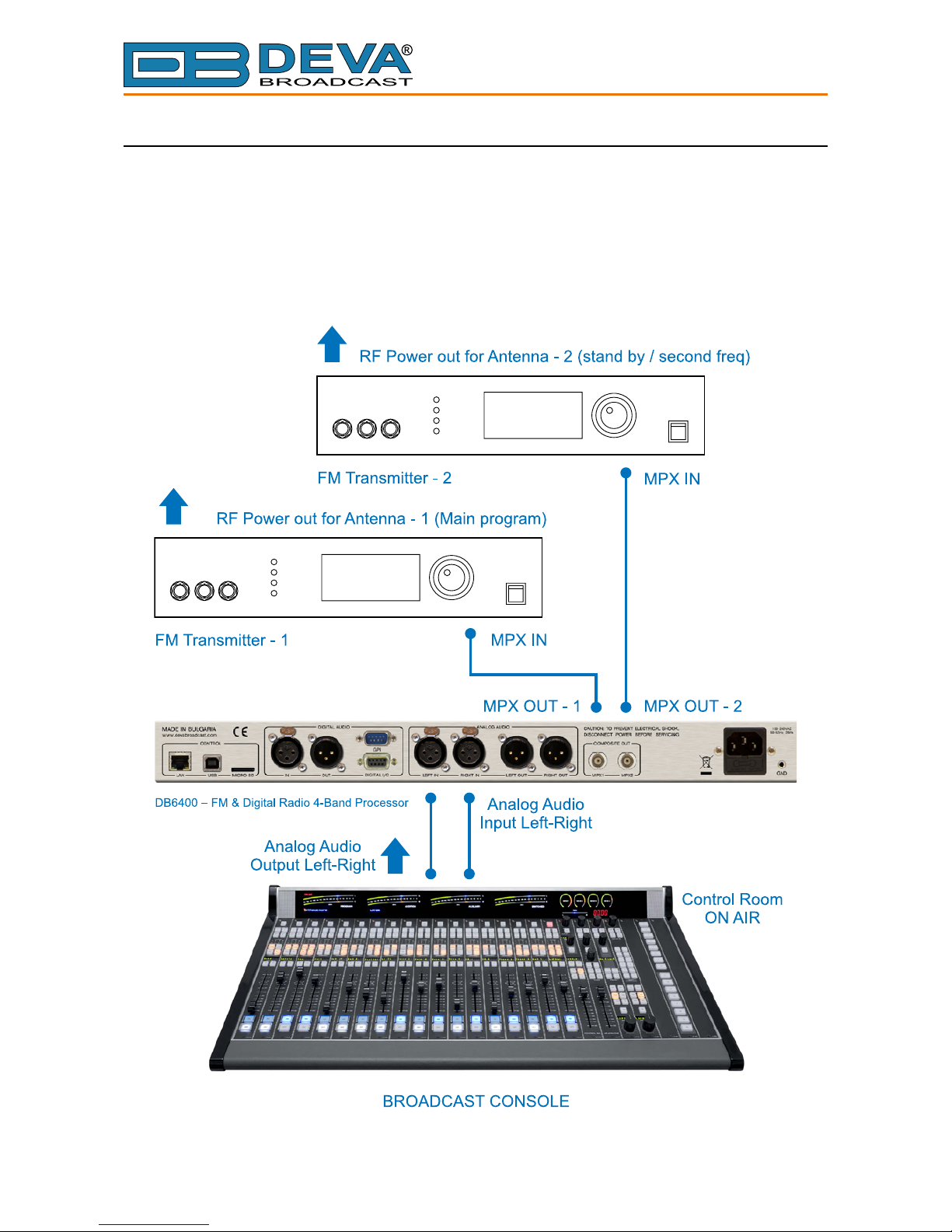
ANALOG CONNECTION WITH TWO TRANSMITTERS
Possible congurations:
- Program transmitter and second standby transmitter;
- Two program transmitters broadcasting on different frequencies via analog audio connection.
The main program output is sent to the DB6400 via XLR connector. The MPX composite
output is sent via BNC connection to the transmitter’s MPX input. The audio processor’s outputs
used are MPX OUTPUT – 1 (for the main program) and MPX OUTPUT – 2 (for the standby/
second frequency).
IMPORTANT RECOMMENDATION: It is mandatory that the cable used for connection
between DB6400’s MPX output, and the MPX input of the transmitter be as short as possible. This
will prevent any face distortion.
Page 28

65 Aleksandar Stamboliyski Str., 8000 Bourgas, Bulgaria
Tel: +359 56 820027, Fax: +359 56 836700
E-mail: ofce@devabroadcast.com ,Web: www.devabroadcast.com
- 28 -
ANALOG CONNECTION WITH DEVA SMARTGEN 6.0
The DB6400 has built in basic RDS/RBDS Encoder, in case additional RDS/RBDS Encoder
is added, a “Loop Through” and “Side-chain” connection with the audio processor can be made.
Side-chain
Side-chain – the RDS& MPX output is sent to the Input SCA input, while to provide the RDS
encoder with a Sync signal for the 19 kHz pilot tone, the entire program can be taken out via MPX
OUT-2. Make sure that you will not send the same signal as the one generated by the RDS encoder
to the MPX OUT-2.
IMPORTANT RECOMMENDATION: It is mandatory that the cable used for connection
between DB6400’s MPX output, and the MPX input of the transmitter be as short as possible. This
will prevent any face distortion.
Page 29

65 Aleksandar Stamboliyski Str., 8000 Bourgas, Bulgaria
Tel: +359 56 820027, Fax: +359 56 836700
E-mail: ofce@devabroadcast.com ,Web: www.devabroadcast.com
- 29 -
Loop through
The output of the DB6400 is wired directly to the PILOT/MPX IN of the SmartGen 6.0. The
output of the RDS encoder will be connected to the composite/MPX input of the FM transmitter.
This connection is not recommended, because the composite signal/MPX passes through the RDS
encoder, and the transmission of the program will be interrupted in case of failure of the RDS
encoder. If you are using SmartGen 6.0, such failure will be prevented, as the DEVA technology
includes a Hardware Bypass between RDS & MPX OUT and MPX Input of the FM Transmitter.
The RDS Subcarrier phase will be locked to the MPX stereo FM Signal on the outside.
Page 30

65 Aleksandar Stamboliyski Str., 8000 Bourgas, Bulgaria
Tel: +359 56 820027, Fax: +359 56 836700
E-mail: ofce@devabroadcast.com ,Web: www.devabroadcast.com
- 30 -
OLED Display, Navigational & Soft Buttons
OLED DISPLAY
DB6400 has an easy to read, high-resolution OLED graphical display that visualizes all
measurements of the received signal and settings. Upon switching it on, the Company Logo and
model of the device will be displayed. After a few seconds the Start-up screen will disappear,
replaced by the Main Screen. This is the starting point of the navigation process.
DB6400’s OLED display has three function areas: Header, Soft Buttons and Main Screen
Working area.
Header area
The Header is located on the left part of the screen. The header content is determined according
to the work area context and may include the following functions:
• GATED FLAG (1) – Will appear if the signal at the input is below the specied in Process>
Input Threshold level.
• BYPASS FLAG (2) – Will appear if the entire processing is bypassed.
• IN (3) – Represents the currently selected active Input. If due to some reason the backup
is activated the input information will start blinking, thus indicating that there is a problem
with the main source.
• OUT (4) – Represents the currently selected active Output and its value. There are two
types of digital output synchronization – internal and external. When the synchronization is
internal the values will appear as depicted. If the output is set to external synchronization,
this will be indicated with the following text - SYNC LOCK. If and due to some reason the
external sync source has been loss, the indication will change to SYNC UNLOCK and start
blinking. Then, the DB6400 will switch to the internal sync source. For further information,
please refer to “Output” on page 68.
• VOL (5) – Indicator showing the phones audio volume;
• TRIG FLAG (6) – Will appear if a preset has been triggered electrically via outside
equipment. The number of the GPI will also be displayed and below will be the currently
used user preset.
• DAYPART FLAG (7) – Will appear when the option is in use.
• Currently selected preset (8)
Page 31

65 Aleksandar Stamboliyski Str., 8000 Bourgas, Bulgaria
Tel: +359 56 820027, Fax: +359 56 836700
E-mail: ofce@devabroadcast.com ,Web: www.devabroadcast.com
- 31 -
Main Screen working area
The Main part of the OLED Screen is where the data changes dynamically, depending on the
selected operating mode. The Menu Screen (shown below) appears upon pressing of the [OK]
Navigational Button. DB6400’s Menu Page contains selectable icons and soft buttons for selecting
modes and functions. Pressing [LEFT] and [RIGHT] arrow buttons will change the icon selection
on the Menu Page. The current selection is shown as a rectangle focus frame around the icon.
Pressing [OK] button will navigate to the corresponding page.
Soft Buttons
Used for navigation through the menus, quick access to the parameters, modes, functions and to
alter their values. The Soft Buttons indicators are placed on the bottom side of the OLED display.
Depending on the currently selected menu context, the indicators change their function. The Soft
Buttons will be referred to as (left-to-right) [SB1], [SB2], [SB3] and [SB4].
The purpose of all Soft Button corresponds to the selected menu page. Most pages have the
same or similar functional areas. The corresponding functions as Function, Menu Page, Parameter
to be changed, etc., linked with the Soft buttons will appear as labels above them.
For example:
[SB1] – Input
[SB2] – Process
[SB3] – Output
[SB4] – Presets
NOTE: On some pages, the Header and Soft button area will disappear in order to expose the
content underneath.
Navigation Buttons
[UP], [DOWN], [LEFT], [RIGHT] and [OK] buttons are used to navigate through the menus,
for selecting various functions and parameters of DB6400. The Main Menu structure has an upand-down basis, expanded with left-to-right branches.
Page 32

65 Aleksandar Stamboliyski Str., 8000 Bourgas, Bulgaria
Tel: +359 56 820027, Fax: +359 56 836700
E-mail: ofce@devabroadcast.com ,Web: www.devabroadcast.com
- 32 -
Menu Pages
The front panel menu is divided into several subsections, each of them containing parameters
important for the processing and monitoring purposes. The most important settings are assigned to
the soft buttons and automatically displayed on the OLED screen upon start-up of DB6400.
[Input]
All important settings to the analog inputs of DB6400, the Fallback sources etc., can be applied
through this menu. In order for the proper work of DB6400 to be guaranteed, the right reference
levels of the digital and analog inputs should be set. For further information, please refer to “Input”
on page 56.
[Process]
All the audio processing path parameters that can be altered as per the user’s requirements are
found here – Name, Input, AGC/Stereo FX, Tone FX, Band, Final Limiter, MPX.
[Output]
Just as the Input menu, all the needed settings to the output levels are applied through here,
allowing quick and easy set-up.
[Presets]
The DB6400 has an extensive set of factory presets and provision of 20 user ones. In order for a
preset to be used, navigate to the desired preset and press the soft button labeled [Load], then [OK]
and the preset will be loaded. For further information on the available presets and how to create a
new one, please refer to “Presets” on page 53.
Page 33

65 Aleksandar Stamboliyski Str., 8000 Bourgas, Bulgaria
Tel: +359 56 820027, Fax: +359 56 836700
E-mail: ofce@devabroadcast.com ,Web: www.devabroadcast.com
- 33 -
Quick access to the most important status and audio parameters is also available via the [UP]
and [DOWN] Arrows keys. Pressing the [UP] key will visualize the following screens:
Processing parameters, represented as bar graphs.
Left and Right Audio Input Levels (dBFS), represented as bar graphs.
Left Input level (dBFS), represented as graph.
Page 34

65 Aleksandar Stamboliyski Str., 8000 Bourgas, Bulgaria
Tel: +359 56 820027, Fax: +359 56 836700
E-mail: ofce@devabroadcast.com ,Web: www.devabroadcast.com
- 34 -
Right Input level (dBFS), represented as graph.
AGC GR (dB), represented as graph.
Stereo Width(%), represented as graph.
Page 35

65 Aleksandar Stamboliyski Str., 8000 Bourgas, Bulgaria
Tel: +359 56 820027, Fax: +359 56 836700
E-mail: ofce@devabroadcast.com ,Web: www.devabroadcast.com
- 35 -
Output Left level(dBFS), represented as graph.
Output Right level(dBFS), represented as graph.
MPX Deviation (%), represented as graph.
Page 36

65 Aleksandar Stamboliyski Str., 8000 Bourgas, Bulgaria
Tel: +359 56 820027, Fax: +359 56 836700
E-mail: ofce@devabroadcast.com ,Web: www.devabroadcast.com
- 36 -
MPX Power (dBr), represented as graph.
HF Limiter GR (dB), represented as graph.
ST Limiter GR (%), represented as graph.
Page 37

65 Aleksandar Stamboliyski Str., 8000 Bourgas, Bulgaria
Tel: +359 56 820027, Fax: +359 56 836700
E-mail: ofce@devabroadcast.com ,Web: www.devabroadcast.com
- 37 -
HD Limiter GB (dB), represented as graph.
FM Limiter GR (dB), represented as graph.
RDS Screen
Page 38

65 Aleksandar Stamboliyski Str., 8000 Bourgas, Bulgaria
Tel: +359 56 820027, Fax: +359 56 836700
E-mail: ofce@devabroadcast.com ,Web: www.devabroadcast.com
- 38 -
Settings
All the needed settings to the DB6400 as regards the Security, Dayparting, Communication,
Trigger ports and Device are applied through this menu.
From the same section the username and password for the WEB interface access can also be
changed.
TRIGGER PORTS
If enabled the remote trigger port will allow you to select any of the rst 8 user presets by
pulling one of the 8 pins on the trigger port socket. If more than one pin is triggered at the same
time, the pin with the lowest number will be with highest priority. For example, if all pins are
pulled low, trigger 1 will be with highest priority.
Trigger port
User
Preset
Number
Trigger Input Pin 1 1
Trigger Input Pin 2 2
Trigger Input Pin 3 3
Trigger Input Pin 4 4
Trigger Input Pin 5 5
Trigger Input Pin 6 6
Trigger Input Pin 7 7
Trigger Input Pin 8 8
USEFUL TIP
In order for factory preset to be triggered, copy the settings of the desired preset in the user
preset section.
Page 39

65 Aleksandar Stamboliyski Str., 8000 Bourgas, Bulgaria
Tel: +359 56 820027, Fax: +359 56 836700
E-mail: ofce@devabroadcast.com ,Web: www.devabroadcast.com
- 39 -
KEYBOARD LOCK
To prevent unauthorized local access, the DB6400 offers password protected keyboard locking.
By default the keyboard is unprotected. To enable this function, using the front panel navigational
menu, go to Settings> Security> Front Panel, then press [OK] and Enable the Access Control
function. Set the preferred 5 digit password and Access Timeout.
Once the keyboard lock function is enabled, every attempt to use it will require a password:
ENTER PASSWORD:0****. Access will be denied upon false entry.
KEYBOARD UNLOCK
If the Keyboard unlock function has been activated by mistake, try to unlock it using the default
password 01234. In order to deactivate the code protection, once the front panel menu is unlocked
follow the menu path Settings> Security> Front Panel> Access Control and then select Disabled.
If you do not manage to unlock the front panel with the default password, nevertheless whether
it has been changed intentionally or not, DB6400 should be returned to its factory defaults in order
for the password security to be disabled.
NOTE: The password consists of 5 digits. The leading zeroes are not shown in the menu, but
should be specied when entering the unlock password. For example, if your password is 123,
when entering the password 00123 should be written.
Page 40

65 Aleksandar Stamboliyski Str., 8000 Bourgas, Bulgaria
Tel: +359 56 820027, Fax: +359 56 836700
E-mail: ofce@devabroadcast.com ,Web: www.devabroadcast.com
- 40 -
RDS
This menu allows you to turn On or Off the RDS Encoder and set the RDS Level. Also, all
basic elements of the RDS/RBDS are gathered in this menu – PI, PS, RT, TA/TP and etc. A list
of alternative frequencies is also available. Each of the 25 AF (Alternative frequencies) are user
dened and can be assigned via the front panel navigational menu.
Another great feature is that the Radio Text can be also edited via the front panel menu. In order
for this to happen, once the relevant menu is selected, the [OK] button should be pressed so that
the text could be edited. Use the [UP] and [DOWN] keys to navigate through the alphabet. Press
[Insert] to save the new text.
DAYPARTING
Dayparting is the practice of dividing the day into several parts, during which a different type
of audio preset to be used for the audio processing. This function will allow a processing pattern
based on the radio’s timetable to be made.
The menu path (using the front panel menu) is Menu> Settings> Dayparts. Then press [OK]
to enter the menu. This subsection contains all the real time clock controls for switching presets.
Enable the Dayparting function in order to use it. There are nine positions at your disposal that
can be set. Select one of them and press [OK] to enter the settings menu. Set the desired Daypart
Week Day. For your convenience, the option Every day is also available through the same menu.
Set the Start Time and Daypart Duration. Then, to nalize the set-up, select the preset that should
be used during this time period. Repeat the same procedure for each of the positions that should
be used.
Page 41

65 Aleksandar Stamboliyski Str., 8000 Bourgas, Bulgaria
Tel: +359 56 820027, Fax: +359 56 836700
E-mail: ofce@devabroadcast.com ,Web: www.devabroadcast.com
- 41 -
Other sections
STEREO
All needed settings in order for your station to be broadcasted in stereo are applied through
here, thus allowing more natural distribution of the sound.
STATUS
Information on the device’s status, IP address, etc. can be found here.
Page 42

65 Aleksandar Stamboliyski Str., 8000 Bourgas, Bulgaria
Tel: +359 56 820027, Fax: +359 56 836700
E-mail: ofce@devabroadcast.com ,Web: www.devabroadcast.com
- 42 -
Factory and User presets
FACTORY PRESETS
The DB6400 has an extensive set of factory presets and provision of 20 user ones. In order for
a preset to be selected/used, navigate to the desired preset and press the soft button labeled [Load],
and then [OK].
How to create and save a User Preset or How to customize your sound
As the factory presets cannot always suit every format and market, each of them can be used as
a basis for the creation of e new user-dened preset. Once you are satised with the result all the
changes could be saved.
IT IS RECOMMENDED the user presets to be created prior to the installation of the DB6400
in the broadcasting chain. Otherwise, any drastic changes of the audio quality and enhancements
will be audible for the listeners.
The procedure is quite simple. Below you will nd a step-by-step description of the process.
1. Start by choosing an empty preset, or a factory preset that you would like to use for a basis of
the new one. The menu path is Main screen> Presets select preset and press the soft button labeled
[Load], then [OK] to conrm the change;
2. Go back to the main menu and select the Process icon - modify the parameters that you think
would improve the enhancement of your signal and will make your station’s sound unique.
Specifying the new preset name is mandatory. If not, the DB6400 will not assign a name and
the newly created preset will be saved as U10:DANCE (for example, if a factory preset is used as
a basis) or U7:-empty- (if user preset is used as a basis).
Page 43

65 Aleksandar Stamboliyski Str., 8000 Bourgas, Bulgaria
Tel: +359 56 820027, Fax: +359 56 836700
E-mail: ofce@devabroadcast.com ,Web: www.devabroadcast.com
- 43 -
3. Once you have nished with the creation of your customized sound/preset, go back to the
Presets page and nd the modied preset. An symbol indicating that some changes are being
made will appear.
4. In order to save the changes, using the front panel keyboard, select one of the user presets
then press the [Save] button. A window requiring verication will appear. Conrm the changes by
pressing the [OK] button. The newly created preset will be automatically chosen as ‘active preset’.
NOTE: Unless the new preset is created by a qualied/experienced broadcaster, it is
recommended no general changes to the base preset to be applied, as this can lead to unwanted
signal distortion.
Page 44

65 Aleksandar Stamboliyski Str., 8000 Bourgas, Bulgaria
Tel: +359 56 820027, Fax: +359 56 836700
E-mail: ofce@devabroadcast.com ,Web: www.devabroadcast.com
- 44 -
WEB Interface
DB6400 is also controlled through a built-in web server. A standard web browser can be used
to monitor its status or to make some adjustments.
There are two options for access to the WEB Interface of DB6400:
• via a standard WEB Browser by specifying the device’s IP address (the IP address should
be manually identied rst);
• via the Network discovery option.
MANUAL IP ADDRESS IDENTIFICATION
Connect the device to a local network or to the Internet by the applied LAN cable. Through the
Front panel navigational menu pressing the [OK] button will enable you to enter the device main
menu.
Using the [RIGHT] navigational button nd the Status section located at the end of the menu.
Press the [OK] Button to enter the Status section. Via the Front panel navigational menu press the
[DOWN] button.
This operation will visualize the screen containing information about the IP Address of the
device. Open a new WEB Browser and enter the device IP address in the address eld then press
[Enter].
NOTE: Due to the inability of some WEB Browsers to read the IP address format displayed
on the screen of the device, the numbers included in the IP Address must be written without the
leading zeros. For example: 192.168.020.095 must be written as 192.168.20.95
A window that requires username and password will appear.
Default values being - username: user or admin, password: pass
Page 45

65 Aleksandar Stamboliyski Str., 8000 Bourgas, Bulgaria
Tel: +359 56 820027, Fax: +359 56 836700
E-mail: ofce@devabroadcast.com ,Web: www.devabroadcast.com
- 45 -
NETWORK DISCOVERY
This is a network setting that denes whether your computer can see (nd) other computers and
devices on the network and whether other computers on the network can see your computer. By
default, Windows Firewall blocks network discovery but you can enable it.
1. Open Advanced sharing settings by clicking the Start button, and then on “Control Panel”.
In the search box, type “Network”, click “Network and Sharing Center”, and then, in the left
pane click “Change advanced sharing settings”;
2. Select your current network prole;
3. Click Turn on network discovery, and then click save changes.
NOTE: If you’re prompted for an administrator password or conrmation, type the password,
provide conrmation or contact your system administrator.
If you have already enabled this function on your computer DB6400 will be automatically
added to the Device list section. The device will be ready for usage and no additional adjustments
will be required except user name and password.
ACCESS
DB6400 provides you with a protected access to the device settings. You can choose between
two types of log in:
1. As an ADMINISTRATOR – it will give you full control over the settings (username:
admin, password: pass);
2. As a USER – this type of log-in will allow you to monitor the device and to choose different
stations without applying settings (username: user, password: pass).
In order to make the necessary adjustments to the device, please log in as an ADMINISTRATOR.
Page 46

65 Aleksandar Stamboliyski Str., 8000 Bourgas, Bulgaria
Tel: +359 56 820027, Fax: +359 56 836700
E-mail: ofce@devabroadcast.com ,Web: www.devabroadcast.com
- 46 -
STATUS
The Status Screen shows all mandatory parameters represented as LED readings, just as the
ones placed on the front panel of DB6400. The LEDs sequence is as per the processing path.
In order for DB6400.’s processing powers to be evaluated, and the difference between the
processed and raw signal to be clearly heard, there is an incorporated [Bypass] option in the form
of a button. When the [Bypass] option is enabled, the entire process will be stopped.
At the top of the control window is placed a constant section, containing information about the
input in use, active preset, Trigger port status (if a factory preset is activated via the trigger port,
the relevant number will be lit), Date/Time and Session Timeout.
At the bottom of the control window is an information bar, gathering all the important connection
parameters – Firmware Version in use, Serial Number, IP Address, and etc.
Upon change of the Web Interface screens, the main status window will resize automatically
and become a constant part of each tab. Thus, allowing reading at a glance of all the mandatory
parameters (Settings pages excluded).
Page 47

65 Aleksandar Stamboliyski Str., 8000 Bourgas, Bulgaria
Tel: +359 56 820027, Fax: +359 56 836700
E-mail: ofce@devabroadcast.com ,Web: www.devabroadcast.com
- 47 -
SETTINGS
The Settings page is divided into several subsections. Each explained in details below.
General
DB6400 provides you with protected access to the device settings. You can choose between two
types of log in.
• As an ADMINISTRATOR – It will give you full control over the device’s settings;
• As a USER – that will allow you to just monitor the device, while all the settings remain
locked.
In order for the security of DB6400 to be enhanced, new username and password could be set
from the Security section.
By choice, you can change the name of the device (General section). Later on, it will be used
as a title name on all WEB pages. Customizing the name will make the device more recognizable.
Date & Time – used for manually determining the current date and time. [Copy Local Time]
button will set the Date & Time to correspond to that of your computer.
SNTP Internet Time – Synchronizes automatically DB6400’s clock time to a millisecond with
the Internet time server. Enable this function in order to use it (Specifying the server closest to your
location will improve the accuracy).
WEB Log – the maximum storage time of the log les is chosen from here. Log les older than
the specied will be permanently deleted.
NOTE: In order the applied settings to be used press the [Save] button, placed on the bottom
right part of the screen.
Page 48

65 Aleksandar Stamboliyski Str., 8000 Bourgas, Bulgaria
Tel: +359 56 820027, Fax: +359 56 836700
E-mail: ofce@devabroadcast.com ,Web: www.devabroadcast.com
- 48 -
Communication
Network
The network addresses could be set manually (static IP) or automatically via a DHCP Server.
To set static IP, MASK, GATEWAY and DNS addresses, the DHCP should be disabled. In order
for the built-in DHCP client to be activated, the function should be enabled. When the DHCP
client is activated, all assigned values will be shown in the relevant elds on the “Status Screen”.
If due to any reason, the DHCP procedure cannot be completed, DB6400 will use Auto IP and will
generate an IP Address.
SNMP Agent
Specify Agent ID, Agent Port, Read/Write Communities, Manager IP, Manager Port and
Session Timeout.
Agent – enables/disables SNMP Agent.
Agent ID – is used for identication of the device among others, when an SNMP notication
is being sent.
Once all needed settings are applied, use the Test button to generate a test notication, which
upon success will be received by the SNMP Manager.
Press the [Download] button to download the latest available DB6000 SNMP MIB le.
NOTE: The MIB le may vary from one rmware revision to another. Downloading this le
from the device, guarantees that you have the proper MIB le.
E-mail
Enter the desired notication recipients in E-mail 1 and/or E-mail 2 elds. Fill in your e-mail
account settings: Sender, Username and Password, Server, SNMP port and Connection Type.
We recommend you to use the [Test] button and generate a test e-mail, which upon success will
be delivered to the specied E-mail 1 and/or E-mail 2.
Example of Test E-mail Message:
DB6400 Test Message.
Please do not reply to this e-mail.
Page 49

65 Aleksandar Stamboliyski Str., 8000 Bourgas, Bulgaria
Tel: +359 56 820027, Fax: +359 56 836700
E-mail: ofce@devabroadcast.com ,Web: www.devabroadcast.com
- 49 -
HTTP Server
Enable/Disable the HTTP Server. Specify the Server Port and Session Timeout.
FTP Server
Enable/Disable the FTP Server. Specify the Command and Data Ports to be used.
Syslog
Enable or disable the Syslog feature. Specify Server Address and Port to be used.
Page 50

65 Aleksandar Stamboliyski Str., 8000 Bourgas, Bulgaria
Tel: +359 56 820027, Fax: +359 56 836700
E-mail: ofce@devabroadcast.com ,Web: www.devabroadcast.com
- 50 -
Dayparts
Dayparting is the practice of dividing the day into several parts, during which a different type
of audio preset to be used for the audio processing. This function will allow a processing pattern
based on the radio’s timetable to be made.
Generally enable the Dayparts function in order to use it. Please bear in mind that if the option
is generally disabled the function will not be used, nevertheless the applied settings in sections
Daypart 1 to Daypart 9.
There are nine positions at your disposal that can be set. The settings to be applied for each of
them are identical:
1. Set the desired Weekday from the drop-down menu. For your convenience, the option
Every day is also available;
2. Set the Start Time and Duration;
3. To nalize the setup, select the preset that should be used during this time period.
Repeat the same procedure for each of the positions that should be used.
NOTE: It is recommended the unused dayparts to be set to Never. Also, please note that if the
Weekday is set to Never the relative daypart will not be used.
Page 51

65 Aleksandar Stamboliyski Str., 8000 Bourgas, Bulgaria
Tel: +359 56 820027, Fax: +359 56 836700
E-mail: ofce@devabroadcast.com ,Web: www.devabroadcast.com
- 51 -
Other
Firmware Update
To update the device rmware, select the new rmware le. After having pressed the [Upload]
button, a dialog window will appear. Conrm the rmware update and wait for the process to
complete.
Storage
Information about the device storage space is found in this section. The internal storage could
be deleted by pressing the [Format] button.
System Log
By pressing the [Clear] button, all recorded in the system log information will be deleted.
Factory Defaults
[Retain Presets and IP] – all settings except for the Network settings (IP Address) and Presets
will be deleted.
[Retain IP] – all settings except for the Network settings (IP address) will be deleted.
To restore DB6400 to its Factory Defaults you should rst select the desired option and then
press the relevant button. A new window will appear - conrm that you want to restore the factory
defaults and wait for the process to be completed. On completion of the process, the settings
should have the proper default values.
Reboot
To start Rebooting of DB6400, press the [Reboot] button. A dialog warning window will appear.
Conrm that you want to reboot the device and wait for the process to be completed.
Page 52

65 Aleksandar Stamboliyski Str., 8000 Bourgas, Bulgaria
Tel: +359 56 820027, Fax: +359 56 836700
E-mail: ofce@devabroadcast.com ,Web: www.devabroadcast.com
- 52 -
Log
All device system events (front panel and WEB activity, presets change) are stored here.
Page 53

65 Aleksandar Stamboliyski Str., 8000 Bourgas, Bulgaria
Tel: +359 56 820027, Fax: +359 56 836700
E-mail: ofce@devabroadcast.com ,Web: www.devabroadcast.com
- 53 -
PRESETS
The DB6400 has a set of 17 factory presets and provision of 10 user ones. A preset contains
all the audio processing path parameters that can be changed in the following tabs – AGC, EQ,
Enhancer, Multiband 1, Multiband 2, and Final Limiter. In order for a preset to be selected/used,
the [Load] button should be pressed (the active preset is illuminated in green).
Each of the factory presets can be used as a basis for creation of new user-dened preset. Once
you are satised with the result all the changes could be saved.
If the Presets are to be triggered via GPI, the option should be enabled via the relevant menu.
The same is applicable for the Dayparting. Edit dayparts is a shortcut to “Dayparts” settings page.
How can a user preset be made?
IT IS RECOMMENDED the user presets to be created prior to the installation of the DB6400
in the broadcasting chain. Otherwise, any drastic changed of the audio quality and enhancements
will be audible for the listeners.
The procedure is quite simple. Below you will nd a step-by-step description of the process:
1. Choose an empty, or factory preset that you would like to use for a basis of the new one;
2. Modify the parameters that you think would improve the enhancement of your signal and
will make your station’s sound unique;
3. Once you are satised with the result, go back to the Presets page. You will notice that in
front of the currently selected preset, a ‘pen symbol’ indicating that some changes are being
made will appear. In order to save the changes select one of the user presets and press the
[Save] button. The following message box will appear:
Specify the preset name and press [OK].
Page 54

65 Aleksandar Stamboliyski Str., 8000 Bourgas, Bulgaria
Tel: +359 56 820027, Fax: +359 56 836700
E-mail: ofce@devabroadcast.com ,Web: www.devabroadcast.com
- 54 -
4. A window requiring verication will appear. Conrm the changes by pressing the [OK]
button;
5. The newly created preset will be automatically chosen as ‘active preset’.
NOTE: Unless the new preset is created by a qualied/experienced broadcaster, it is
recommended that no general changes to the base preset (if such is used) to be applied, as this can
lead to unwanted signal distortion.
Preset Lock
As many of the stations prefer to use the services of qualied personnel when creating the
perfect preset, the DB6400 supports the function the newly created preset to be locked. The preset
can be locked upon its export. The following options are available:
Key – the preset will be locked with a key known only by the creator. Thus, only users familiar
with it would be able to import it into devices different than the one used for the purposes of
creation;
Serial – you can specify the serial number of the device on which the preset can be used. Only
the unit with this serial number will be able to import this preset. If the preset should be used
only by the current device, press [This device] button and the serial number will be automatically
assigned.
Depending on your preferences, both, one or none of the above explained options can be used.
Presets Export
In order for a user preset to be exported the following procedure should be completed:
1. Select the preset to be exported via the [Export] button. The following message box will
appear:
2. If the preset is to be lock – complete the needed information. If not, press the [OK] button
to continue;
3. Conrm to save the le on your computer.
Page 55

65 Aleksandar Stamboliyski Str., 8000 Bourgas, Bulgaria
Tel: +359 56 820027, Fax: +359 56 836700
E-mail: ofce@devabroadcast.com ,Web: www.devabroadcast.com
- 55 -
Presets Import
1. Press the [Import] button on the desired position. The following message box will appear:
2. Browse the le to be imported and specify Key if it has been locked. Then press [OK] to
continue;
3. The newly uploaded preset will be automatically chosen as ‘active preset’.
If the preset has been protected by password, or has been assigned to a specic device (via the
Serial function) the following message will appear:
The same message will appear if the le is corrupted.
Presets Delete
The user presets can be changed or overwritten, but not deleted.
Page 56

65 Aleksandar Stamboliyski Str., 8000 Bourgas, Bulgaria
Tel: +359 56 820027, Fax: +359 56 836700
E-mail: ofce@devabroadcast.com ,Web: www.devabroadcast.com
- 56 -
INPUT
General – Several types of Main Audio Sources could be set – Main Analog, AUX Analog,
Main Digital, AUX Digital, MP3 Player and IP Stream.
When setting the Input Gain level, have in mind that the applied settings have inuence over
the processed signal after the Input bargraph, thus meaning that the bargraph values will not change
when altering the value of the Input gain.
Fallback – DB6400 supports up to 3 fallback sources. In order for a source to be used a backup
should be specied. The following options are available - Main Analog, AUX Analog, Main
Digital, AUX Digital, IP Audio Client, MP3 Player. The conditions when backup source has to
be used should also be specied (Loss Threshold and Loss Timeout).
Test Generator – There are several modes of operation – Left+Right, Left-Right, Left, and
Right. Set the Level and the Frequency of the signal at which the generator should process. The
‘Test Generator’ will generate a test signal with which the DB6400 and the equipment connected
to its outputs could be examined.
IP Audio Client – Set Decoder from the drop-down menu, and URL of the stream server. Up
to 3 URLs can be dened. Up to 63 characters can be entered.
• Decoder (+ Sample rate) – Select decoder and sample rate. It can be set to Auto or set
manually to preferred decoder and sample rate. In Auto Mode, the DB6400 will adjust
decoder and sample rate, using stream supplied information. For PCM (uncompressed)
sample rate can be 32, 44.1 or 48 kHz. For MPEG1 the sample rate is determined
automatically from the stream.
• Pre-buffer – The minimum amount of time in which the unit will prebuffer before playing
starts in order for problems with the connection to be prevented.
Analog/Digital Inputs – Set the peak levels of the analog/digital inputs. This corresponds to
the absolute maximum level that the input could receive i.e. the user guarantees that the fed level
will not exceed the one specied. The specied level in dBu corresponds to 0 dBFS.
Page 57

65 Aleksandar Stamboliyski Str., 8000 Bourgas, Bulgaria
Tel: +359 56 820027, Fax: +359 56 836700
E-mail: ofce@devabroadcast.com ,Web: www.devabroadcast.com
- 57 -
MP3 Audio Player – The Playback Order can be changed from here. The following options
are available: A-Z, Z-A, Shufe, Playlist, and Shufed Playlist. Information on the used and
available SD card storage respectively, could also be found in this section. [Repeat] and [Next]
button to navigate through the playlist if need be, are also available.
MP3 Files Upload via FTP –Through the use of a standard FTP client, you have the opportunity
to update the backup content at will via any PC. The supported format is .m3u. An important
requirement for the MP3 Player conguration is that all MP3 les should be stored in a folder
named Audio (no sub-folders are allowed). The folder should be located in the root of the SD Card.
The playlist le must be named playlist.m3u.
For information on how the connection between the DB6400 and an FTP Client should be
congured, please refer to “APPENDIX B” on page 72.
Page 58

65 Aleksandar Stamboliyski Str., 8000 Bourgas, Bulgaria
Tel: +359 56 820027, Fax: +359 56 836700
E-mail: ofce@devabroadcast.com ,Web: www.devabroadcast.com
- 58 -
AGC
The rst processing stage is the AGC. It works across a large band of frequencies, and is intended
to normalize the difference in the audio levels fed at DB6400’s input. The AGC effectively reduces
the volume if the signal is strong and raises it when it is weaker. Having the task is to even out the
variances and to create a consistent performance, the AGC has inuence over all the subsequent
processes.
AGC Gate – if turned [On], in the event of audio drops below the user set limit (in dB), this
threshold will pause the operation of the audio processor. Hence limiting the unwanted oor noise
when the signal is too low.
AGC – this section allows you to set the Drive, Attack and Release. When setting these
parameters, have in mind:
- Drive (dB) – depending on the value set, it will increase or decrease the gain at the AGC input.
Increasing the drive will compensate for the very low levels, and vice-versa - the low drive will
prevent the low level corrections at the input.
- Attack – set in dB per second, this value will dene the AGC’s speed of reaction to unexpected
volume increase.
- Release – sets the AGC correction speed in dB per second. It is not mandatory high Release
speed to be set, as the AGC is powerful enough tool. It is widely recommended the speed to be set
to 1dB/s and 1.5dB/s for classical music, and to 2dB/s for all other commercial programs.
High Pass Filter – this sections allows you to turn [On] and [Off] the HP lter that passes
signals with a frequency higher than the set HPF Freq (High Pass Filter Frequency), and attenuates
signals with frequencies lower than the set HPF Freq (High Pass Filter Frequency). If the Stereo
Link is turned [On], the audio processor will check for differences between levels of the left and
right audio channel, and if need be, will restore the levels at the output. This feature is very useful
for jazz and classical programs, as when applied to pop/rock programs it may lead to sound power
loss.
Page 59

65 Aleksandar Stamboliyski Str., 8000 Bourgas, Bulgaria
Tel: +359 56 820027, Fax: +359 56 836700
E-mail: ofce@devabroadcast.com ,Web: www.devabroadcast.com
- 59 -
EQUALIZER
DB6400 has four separate sections of ‘parametric’ equalization, which can be attributed to any
combination of Freq (frequency), Q Factor (bandwidth) and Gain (amplitude). These may be
assigned to any combination of low frequency EQ, mid-band EQ and top-end EQ chores. However,
all four sections are identical and each of them may be programmed in frequency between 50 Hz
and 15 kHz. Of course, there is an option the equalizer to be enabled or disabled.
Within each section of parametric equalization, the Freq, Q Factor and Gain are individually
adjustable. The sliders of the EQ Section panel select the frequency range, and identical ranges are
available in each equalizer section. As each EQ slider is moved, the resultant change in response,
both in that EQ section and its overall contribution, is shown on the graph.
The graph placed on the bottom of the tab, displays the individual frequency response of each of
the four equalizer bands and the summary frequency response of the entire EQ section, including
pre-emphasis. Each band has a pre-dened color visible on the bottom right of the graph.
Page 60

65 Aleksandar Stamboliyski Str., 8000 Bourgas, Bulgaria
Tel: +359 56 820027, Fax: +359 56 836700
E-mail: ofce@devabroadcast.com ,Web: www.devabroadcast.com
- 60 -
ENHANCER
The DB6400 is equipped with real stereo enhancer intended to improve the existing stereo
image. However, bear in mind that it will not create stereo from mono sources.
The Stereo Enhancer can be either turned [On] or [Off]. The Stereo Width parameter sets the
stereo enhancement rate. The sufcient value widely recommended is between 20 and 40%.
DJ Bass can be either turned [On] or [Off]. It is intended to enhance the sound in the low-audio
frequency range.
Brilliance can be either turned [On] or [Off]. It is intended to control the output level of the
tweeter for proper relative volume between the treble and the low audio frequencies.
Page 61

65 Aleksandar Stamboliyski Str., 8000 Bourgas, Bulgaria
Tel: +359 56 820027, Fax: +359 56 836700
E-mail: ofce@devabroadcast.com ,Web: www.devabroadcast.com
- 61 -
MULTIBAND 1 (MULTIBAND LIMITER)
Split-band ltering is a great technique where audio signal can be separated into different
frequency bands so that each band can be processed separately. Upon completion of the procedure,
the respective bands can be combined together to form a more coherent and dynamic sound.
Graphic visualization of the frequency bands is also available.
Processing – the multi band processing an unique algorithm that controls the gain in each band
so as to assure sound stability. The sound color is controlled by the Fidelity parameter. It allows
either a pure or a colorful sound texture to be obtained. The Sound Impact algorithm will keep
the original authenticity of the sound attacks (peaks). The [On] and [Off] buttons in this section
enable or disable generally the Gate, Sound Impact and Fidelity options for the bass, low, middle
and high bands.
NOTE: The Multiband process is very powerful and can absorb the important sound variations.
That is why is it not always necessary to use the AGC stage.
The Multiband limiters are used to restrain in limits each of the bands to prevent distortion in the
processing control system. Each of the parameters can be changed as per the user’s requirements.
The settings to be applied are identical for some of the subsections and are described in details
below.
Gate – When the audio drops below this user dened threshold limit, the DB6400 will freeze
operation band. When the signal is too low, this function will limit the oor noise.
Fidelity – This function controls the spectral balance between bands. For example:
• if the Fidelity = 0%, the bands will work independently and the sound will be more colorful;
• if the Fidelity = 100%, the bands will be linked to the spectral distribution at the input, and the
sound will be purer.
Page 62

65 Aleksandar Stamboliyski Str., 8000 Bourgas, Bulgaria
Tel: +359 56 820027, Fax: +359 56 836700
E-mail: ofce@devabroadcast.com ,Web: www.devabroadcast.com
- 62 -
Sound impact – As explained, this option keeps the original authenticity of the sound attacks
(peaks). Pay attention when using the Sound Impact with value bigger than 6dB, as the average
power of the sound will be signicantly increased. In such cases, you may need to lower the band
limiter or nal limiter drive.
Drive – it is intended to create more or less gain at the input of the band. When setting the drive,
note that:
• Increasing the drive will lead to reduction in the gain created by the band process. This will
make up for the very low levels.
• A very low drive will prevent low level corrections’
• If you are not using the wide band AGC, we recommend the drive to the bands to be pushed,
so that the reduction to be sufcient and correct low levels.
Threshold – sets working limits for each band. It can also move bands from the background to
foreground and vice versa.
Attack – Adjust in dB per second to set the processors’ reaction speed for each band. When
setting the attack parameter bear in mind that:
• If lower value is set, the slower will the processor react.;
• If higher the value is set, the faster the processor react, thus controlling the rapid variations.
Release – is often associated with density. Indeed, the higher the release time is, the higher the
spectrum density within the band will be. When setting this parameter, bear in mind that the Band
processor is very powerful. Therefore, it is not necessary high release time to be set in order for
high density levels to be obtained.
Page 63

65 Aleksandar Stamboliyski Str., 8000 Bourgas, Bulgaria
Tel: +359 56 820027, Fax: +359 56 836700
E-mail: ofce@devabroadcast.com ,Web: www.devabroadcast.com
- 63 -
MULTIBAND 2 (MULTIBAND LIMITER)
Multiband 2 (Multiband Limiter) is intended to prepare the processed audio for the nal limiter.
The applicable settings for each band have been simplied so as not to complicate the process with
useless parameters. For each of the limiters you can set Drive and Threshold.
Drive – It is intended to create more or less gain at the band limiter input.
Threshold – sets the limit for each limiter band.
Band Mix – This section allows you to dose the output level for each band, hence, obtaining
the best sound balance.
Page 64

65 Aleksandar Stamboliyski Str., 8000 Bourgas, Bulgaria
Tel: +359 56 820027, Fax: +359 56 836700
E-mail: ofce@devabroadcast.com ,Web: www.devabroadcast.com
- 64 -
FINAL LIMITER
Stereo Limiter – set the stereo image reduction percentage required, compared with the
maximum rate of 100%. If you are already using the Stereo Enhancer, we recommend you use a
percentage value between 10 and 15%.
HF Limiter – set in dB the HF limiter is intended to increase or decrease the amount of high
frequencies to be processed.
HD Limiter – is developed and dedicated for high quality digital applications such as HD /
DAB / DRM. This is a ‘Look-Ahead’ type of limiter, the delay of which can be adjusted. When
used in this mode, the outputs are not limited to 15 kHz.
FM Limiter – as the HD Limiter, the FM Limiter is intended for the FM applications. In its
core, it is a very powerful clipper that controls the gain at the FM limiter input. Bear in mind that
increasing the FM limiter drive may lead to signicant sound distortion.
FM Pre-emphasis – set the preferred pre-emphasis type - Flat, 50μS for Europe and 75μS for
USA. This setting is applicable for the FM output only
Page 65

65 Aleksandar Stamboliyski Str., 8000 Bourgas, Bulgaria
Tel: +359 56 820027, Fax: +359 56 836700
E-mail: ofce@devabroadcast.com ,Web: www.devabroadcast.com
- 65 -
MPX
The settings of the Stereo generator are applied through this section of the WEB Interface.
General – three modes of operation are available. The output can be set to [MPX], [Stereo] and
[Mono]. The option [Bypass] is also available.
Stereo Adjustment – from here you can change the level and phase of the PILOT tone.
MPX Limiter – from here you can turn [On] or [Off] the Virtual Limiter. The MPX Drive is
adjustable from 0dB to 10dB via the interactive slider.
RDS Encoder – The DB6400 has a built-in RDS generator which, depending on your preferences
can be [Enabled ]or [Disabled]. The RDS subcarrier level can also be changed.
Output – Select the preferred output mode – [MPX+MPX] or [MPX+Pilot].
BS-412 ITU Limiter – Limits the MPX Power as per the ITU BS412 directive. The authorities
in each country have set different parameters that should be observed. It is recommended your
local authorization to be checked.
Page 66

65 Aleksandar Stamboliyski Str., 8000 Bourgas, Bulgaria
Tel: +359 56 820027, Fax: +359 56 836700
E-mail: ofce@devabroadcast.com ,Web: www.devabroadcast.com
- 66 -
RDS DATA
All basic elements of the RDS/RBDS are displayed on the screen – PI, PS, RT, TA/TP and etc.
The Alternative frequencies are also available, represented as a list. The number of the AF can
be set via the AF Count Slider. Once the needed quantity of AFs is set, the frequencies for each of
them should be specied.
Basic RDS
PI/CALL (Program Identication) – The PI code is your station’s ‘digital address’. It is a
hexadecimal code that is assigned by an appropriate broadcasting authority in most countries,
but in the United States the PI code is numerically calculated from the station’s call sign. We
have provided a calculator utility within the DB6400. An in-depth discussion of the mathematical
calculation is given in RDS/RBDS Standard.
To use the PI calculator for US ‘K’ and ‘W’ call signs, simply enter call letters into the CALL
box. The hexadecimal code will automatically be calculated into PI box. If the hexadecimal code
for a US station is known, you may enter it under PI, and then the call sign will be calculated
automatically into CALL box.
When PI calculator fails to calculate PI or CALL the corresponding box will be lled with ‘----’.
PS (Program Service Name) – This is the station’s “street name” that will appear on the
receiver faceplate display. The PS can be up to eight characters in length (including spaces) and
can be as simple as the station’s call letters: KWOW or KWOW FM, or a slogan: NEWSTALK or
LIVE 95.
RT (Radio Text) – This is a 64-character block of plain text that the listener can select for
visual display on the faceplate of the radio by pressing an INFO button on the receiver. This
function is not available on many automobile radios for safety reasons, which has precipitated the
frowned-upon practice of scrolling the PS eld instead. The Radio Text can announce song titles
and performers, run special promotions or contests, or broadcast sponsors’ messages.
Page 67

65 Aleksandar Stamboliyski Str., 8000 Bourgas, Bulgaria
Tel: +359 56 820027, Fax: +359 56 836700
E-mail: ofce@devabroadcast.com ,Web: www.devabroadcast.com
- 67 -
PTY (Program Type) – The PTY data ag identies the station format from a pre-dened
categories. Many RDS receivers are able to seek the listener’s preferred format automatically.
This means that a car radio can switch from a fading station to a stronger one that carries the
same variety of music, though not the very same program, as provided by AF switching. The PTY
function of RDS helps a broadcaster catch ‘transient audience’ share. The PTY code is not meant
to change from song to song or to accommodate a top-of-the-hour newscast, however.
MS (Music/Speech Switch) – This ag simply indicates whether music or speech is the primary
broadcast programming.
TP (Trafc Program Identication) – The TP ag identies the station as one that routinely
broadcasts trafc bulletins for motorists as part of its normal, everyday programming. When the
TP ag is displayed on the receiver faceplate, the radio is searching for trafc announcements. The
radio keeps track of TP stations offering this service to speed up the search-and-switch process.
TA (Trafc Announcement) – This is a temporary ag added to the RDS data stream only
when a trafc bulletin is being aired. Some RDS car radios can be set to search for trafc bulletins
among various TP stations while tuned to a listener’s preferred program, or even while playing
a tape or CD. As soon as any TP station broadcasts a trafc bulletin, the receiver temporarily
switches-over to receive it. When the bulletin is nished, the receiver switches back to the original
program, tape or CD.
DI (Decoder Information) – This is one of several ‘ags’ that convey yes/no or other very
basic data. This particular ag tells the receiver whether the broadcast is monaural, or is being
transmitted in any of several methods of stereo or binaural broadcasting.
List of Alternative Frequencies – A network broadcaster, or one with low-power rebroadcast
transmitters (translators) to ll holes in his coverage area, can include a list of all frequencies where
the identical program can be heard simultaneously. The RDS receiver (particularly the upscale car
radio) constantly searches for the best signal that carries the very same program. When a better
signal is found, the radio re-tunes with no noticeable interruption. The principal utility of this RDS
function is with European radio networks and US stations with ‘translators.’
Page 68

65 Aleksandar Stamboliyski Str., 8000 Bourgas, Bulgaria
Tel: +359 56 820027, Fax: +359 56 836700
E-mail: ofce@devabroadcast.com ,Web: www.devabroadcast.com
- 68 -
OUTPUT
All the needed settings to the outputs can be applies through here. Each of the available outputs
is separated in different sections.
Digital Output / Analog and Headphones Output – is intended to control the peak output
level of the digital and analog output. A De-emphasis option is provided on both the analogue and
digital outputs. The following control options are available – FLAT (off), 50μs (for Europe) and
75μs (for USA).
The Digital Output should be internally or externally synchronized in order to be functioning
correctly. This is specied by the Sample rate setting. If the synchronization should be made
internally, a value from the standard range of 32 to 192 kHz should be chosen. If the synchronization
method is external, the relevant option should be selected from the drop-down menu. When
External synchronization is chosen, Sync loss s.r. and Sync tout should be set in order for possible
loss of the audio at the digital output to be prevented. If such is present, the DB6400 will switch
to internal synchronization (the value being specied in Sync loss s.r.) after the dened Sync
Timeout expires.
MPX Out Level should match the one of the transmitter (or link device if one is used).
HD Time Alignment – Because of the time delay in the digital portion of the HD Radio audio
path, the analog and digital signals are supposed to be time-aligned. When the alignment is correct,
the transitional blend from analog to digital or vice-versa will be almost transparent. When setting
this parameter, have in mind that a time-alignment error of 1 millisecond will cause spectral
notches during transition which will be audible by the listeners.
IT IS RECOMMENDED when the HD time Alignment is not used, the slider (value) to be set
to 0 ms as by default. Otherwise the result will be undesired audio delay.
Page 69

65 Aleksandar Stamboliyski Str., 8000 Bourgas, Bulgaria
Tel: +359 56 820027, Fax: +359 56 836700
E-mail: ofce@devabroadcast.com ,Web: www.devabroadcast.com
- 69 -
WARRANTY TERMS AND CONDITIONS
I. TERMS OF SALE: DEVA Broadcast Ltd. products are sold with an understanding of “full
satisfaction”; that is, full credit or refund will be issued for products sold as new if returned to the
point of purchase within 30 days following their receipt, provided that they are returned complete
and in an “as received” condition.
II. CONDITIONS OF WARRANTY: The following terms apply unless amended in writing
by DEVA Broadcast Ltd.
A. The Warranty Registration Card supplied with this product must be completed and returned
to DEVA Broadcast Ltd. within 10 days of delivery.
B. This Warranty applies only to products sold “as new.” It is extended only to the original enduser and may not be transferred or assigned without prior written approval by DEVA Broadcast Ltd.
C. This Warranty does not apply to damage caused by improper mains settings and/or power
supply.
D. This Warranty does not apply to damage caused by misuse, abuse, accident or neglect. This
Warranty is voided by unauthorized attempts at repair or modication, or if the serial identication
label has been removed or altered.
III. TERMS OF WARRANTY: DEVA Broadcast Ltd. products are warranted to be free from
defects in materials and workmanship.
A. Any discrepancies noted within TWO YEARS of the date of delivery will be repaired
free of charge, or the equipment will be replaced with a new or remanufactured product at
DEVA Broadcast Ltd. option.
B. Parts and labor for factory repair required after the one-year Warranty period will be billed
at prevailing prices and rates.
IV. RETURNING GOODS FOR FACTORY REPAIR:
A. Equipment will not be accepted for Warranty or other repair without a Return Authorization
(RA) number issued by DEVA Broadcast Ltd. prior to its return. An RA number may be obtained
by calling the factory. The number should be prominently marked on the outside of the shipping
carton.
B. Equipment must be shipped prepaid to DEVA Broadcast Ltd.. Shipping charges will be
reimbursed for valid Warranty claims. Damage sustained as a result of improper packing for return
to the factory is not covered under terms of the Warranty and may occasion additional charges.
Page 70

65 Aleksandar Stamboliyski Str., 8000 Bourgas, Bulgaria
Tel: +359 56 820027, Fax: +359 56 836700
E-mail: ofce@devabroadcast.com ,Web: www.devabroadcast.com
- 70 -
PRODUCT REGISTRATION CARD
• All elds are required, or warranty registration is invalid and void
Your Company Name
Contact
Address Line 1
Address Line 2
City
State/Province ZIP/Postal Code
Country
E-mail Phone Fax
Which DEVA Broadcast Ltd. product did you purchase?
Product Serial #
Purchase date / / Installation date / /
Your signature*
*Signing this warranty registration form you are stating that all the information provided to DEVA Broadcast Ltd. are truth and correct.
DEVA Broadcast Ltd. declines any responsibility for the provided information that could result in an immediate loss of warranty for
the above specied product(s).
Privacy statement: DEVA Broadcast Ltd. will not share the personal information you provide on this card with any other parties.
Page 71

65 Aleksandar Stamboliyski Str., 8000 Bourgas, Bulgaria
Tel: +359 56 820027, Fax: +359 56 836700
E-mail: ofce@devabroadcast.com ,Web: www.devabroadcast.com
- 71 -
APPENDIX A
RDS: EUROPE VS AMERICA
The European Broadcasting Union (EBU) and its member countries originated the concept of
“Radio Data” transmission. The European RDS specication, CENELEC Standard EN50067, was
rst published in 1984. It was revised in 1986, 1990, 1991 and 1992.
European RDS has grown in use following initial adoption of the Standard. RDS is nearly
universal throughout Europe; it is almost impossible to nd a European FM broadcasting station
that does not carry a radio data subcarrier.
The popularity of RDS in Europe is very much in contrast with initial reluctance on the part
of US broadcasters to embrace this technology. This can be ascribed to material differences in
broadcasting practices.
Almost without exception, FM broadcasting in the United States is ‘detached’ and independent
- each station originates its own programming. America’s National Public Radio might be
considered as an exception, though for most of the broadcast day even NPR stations originate, or
at least schedule, their own programs.
Most of European broadcasting is similar to the concept of network radio that was common in
the US prior to the 1950s. In Europe, a central program originator may have many transmitting
facilities of modest power situated throughout the country, at several different frequencies to
blanket a designated service area. The European disposition, toward lower-power transmitters can
be found on the “local radio” level, as well.
The European concept of a service area equates to the US broadcaster’s market. The subtle
difference between these designations further characterizes broadcasting practices and ethics.
RDS benets the European broadcaster through almost an altruistic endeavor to be of service to
his listeners. The US broadcaster is marketing his programming and is primarily interested in how
he can create additional revenue from RDS.
THE RDS SYSTEM
RDS is a digital data channel, transmitted as a low-level subcarrier above the range of the
composite stereo program signal in the FM baseband. The data transmission (baud) rate is
comparatively low, yet it is quite robust because of data redundancy and effective error correction.
It is not within the scope of this Manual to cover the details of RDS subcarrier coding and
modulation. For this, the reader is directed to the Specication appropriate to his location either the
CENELEC EN50067 Specication for Europe or the United States NRSC Specication. Since the
Manual will deal with specic implication of RDS implemented with the DB6400, it is assumed
that the user is familiar with the RDS concept.
Page 72

65 Aleksandar Stamboliyski Str., 8000 Bourgas, Bulgaria
Tel: +359 56 820027, Fax: +359 56 836700
E-mail: ofce@devabroadcast.com ,Web: www.devabroadcast.com
- 72 -
APPENDIX B
HOW SHOULD I CONFIGURE THE CONNECTION BETWEEN MY
DEVA DEVICE AND AN FTP CLIENT?
In order for a connection to be established the following setting should be applied:
1. FTP Server Settings
The built-in FTP Server has four important parameters that should be congured: Command
Port, Data Port, User name and Password. These parameters are to be used in the FTP client’s
connection conguration. Further information on how to change the FTP Server’s settings and
their respective default values can be found in the device’s User manual.
WE RECOMMEND the usage of FileZilla (https://lezilla-project.org). This is a widespread
open source software distributed free of charge, hence available for downloading from the Internet.
NOTE: The FTP Server can manage only one connection at a time. TheFTP Server works in
Passive mode. Hence, the FTP Client should also be set in passive mode.
2. IP Router and Port Translation Settings
If the connection to the device is made through a Network address translation (NAT) router or
rewall, the port forwarding feature of the router should be congured. The port forwarding is
usually set in the rewall section of the router’s menu. As each router has different port forwarding
procedure, we recommend you to refer to its complete manual. To allow proper data ow through
the router, the FTP Command and FTP Data ports should be open.
NOTE: The FTP port numbers to be used in the port forwarding feature conguration can be
found in the device.
Page 73

65 Aleksandar Stamboliyski Str., 8000 Bourgas, Bulgaria
Tel: +359 56 820027, Fax: +359 56 836700
E-mail: ofce@devabroadcast.com ,Web: www.devabroadcast.com
- 73 -
3. Example of FTP Client (FileZilla) Settings
In some cases, FileZilla’s “Quick connect” feature is not able to connect with the DEVA unit.
That is why we recommend the device to be assigned in the program manually.
Enter the FTP Client and go to: File > Site manager > New Site. A dialog box requiring
obligatory information about the device will appear. Fill in the needed information and press “OK”.
Select “Transfer Settings” sub-menu and apply the settings as shown below:
Page 74

65 Aleksandar Stamboliyski Str., 8000 Bourgas, Bulgaria
Tel: +359 56 820027, Fax: +359 56 836700
E-mail: ofce@devabroadcast.com ,Web: www.devabroadcast.com
- 74 -
APPENDIX C.1
PTY Code Description Used in RBDS Mode – North America
PTY Short Name
Description
1 News
News reports, either local or network in origin.
2 Information
Programming that is intended to impart advice.
3 Sports
Sports reporting, commentary, and/or live event coverage, either local or
network in origin.
4 Talk
Call-in and/or interview talk shows either local or national in origin.
5 Rock
Album cuts.
6 Classic Rock
Rock oriented oldies, often mixed with hit oldies, from a decade or more ago.
7 Adult Hits
An up-tempo contemporary hits format with no hard rock and no rap.
8 Soft Rock
Album cuts with a generally soft tempo.
9 Top 40
Current hits, often encompassing a variety of rock styles.
10 Country
Country music, including contemporary and traditional styles.
11 Oldies
Popular music, usually rock, with 80% or greater non-current music.
12 Soft
A cross between adult hits and classical, primarily non-current softrock originals.
13 Nostalgia
Big-band music.
14 Jazz
Mostly instrumental, includes both traditional jazz and more modern “smooth
jazz.”
15 Classical
Mostly instrumentals, usually orchestral or symphonic music.
16 Rhythm and Blues
A wide range of musical styles, often called “urban contemporary.”
17 Soft R and B
Rhythm and blues with a generally soft tempo.
18 Foreign Language
Any programming format in a language other than English.
19 Religious Music
Music programming with religious lyrics.
20 Religious Talk
Call-in shows, interview programs, etc. with a religious theme.
21 Personality
A radio show where the on-air personality is the main attraction.
22 Public
Programming that is supported by listeners and/or corporate sponsors instead
of advertising.
23 College
Programming produced by a college or university radio station.
24 Spanish Talk
Call-in shows, interview programs, etc. in the Spanish language
25 Spanish Music
Music programming in the Spanish language
26 Hip-Hop
Popular music incorporating elements of rap, rhythm-and-blues, funk, and soul
27-28 Unassigned
29 Weather
Weather forecasts or bulletins that are non-emergency in nature.
30 Emergency Test
Broadcast when testing emergency broadcast equipment or receivers. Not
intended for searching or dynamic switching for consumer receivers. Receivers
may, if desired, display “TEST” or “Emergency Test”.
31 Emergency
Emergency announcement made under exceptional circumstances to give
warning of events causing danger of a general nature. Not to be used for
searching - only used in a receiver for dynamic switching.
NOTE: These denitions can differ slightly between various language versions.
Page 75

65 Aleksandar Stamboliyski Str., 8000 Bourgas, Bulgaria
Tel: +359 56 820027, Fax: +359 56 836700
E-mail: ofce@devabroadcast.com ,Web: www.devabroadcast.com
- 75 -
APPENDIX C.2
PTY Code Description Used in RDS Mode – Europe, Asia
PTY Short Name Description
1 News Short accounts of facts, events and publicly expressed views, reportage and actuality.
2 Current affairs Topical program expanding or enlarging upon the news, generally in different presentation
style or concept, including debate, or analysis.
3 Information Program the purpose of which is to impart advice in the widest sense.
4 Sport Program concerned with any aspect of sport.
5 Education Program intended primarily to educate, of which the formal element is fundamental.
6 Drama All radio plays and serials.
7 Culture Programs concerned with any aspect of national or regional culture.
8 Science Programs about the natural sciences and technology.
9 Varied Used for mainly speech-based programs usually of light-entertainment nature, not covered
by other categories. Examples include: quizzes, games, personality interviews.
10 Pop Commercial music, which would generally be considered to be of current popular appeal,
often featuring in current or recent record sales charts.
11 Rock Contemporary modern music, usually written and performed by young musicians.
12 Easy Listening Current contemporary music considered to be “easy-listening”, as opposed to Pop, Rock
or Classical, or one of the specialized music styles, Jazz, Folk or Country. Music in this
category is often but not always, vocal, and usually of short duration.
13 Light classics Classical Musical for general, rather than specialist appreciation. Examples of music in this
category are instrumental music, and vocal or choral works.
14 Serious classics Performances of major orchestral works, symphonies, chamber music etc., and including
Grand Opera.
15 Other music Musical styles not tting into any of the other categories. Particularly used for specialist
music of which Rhythm & Blues and Reggae are examples.
16 Weather Weather reports and forecasts and Meteorological information.
17 Finance Stock Market reports, commerce, trading etc.
18 Children’s
programs
For programs targeted at a young audience, primarily for entertainment and interest, rather
than where the objective is to educate.
19 Social Affairs Programs about people and things that inuence them individually or in groups. Includes:
sociology, history, geography, psychology and society.
20 Religion Any aspect of beliefs and faiths, involving a God or Gods, the nature of existence and ethics.
21 Phone In Involving members of the public expressing their views either by phone or at a public forum.
22 Travel Features and programs concerned with travel to near and far destinations, package tours and
travel ideas and opportunities. Not for use for Announcements about problems, delays, or
roadworks affecting immediate travel where TP/TA should be used.
23 Leisure Programs concerned with recreational activities in which the listener might participate.
Examples include, Gardening, Fishing, Antique collecting, Cooking, Food & Wine etc.
24 Jazz Music Polyphonic, syncopated music characterized by improvisation.
25 Country Music Songs which originate from, or continue the musical tradition of the American Southern
States. Characterized by a straightforward melody and narrative story line.
26 National Music Current Popular Music of the Nation or Region in that country’s language, as opposed to
International ‘Pop’ which is usually US or UK inspired and in English.
27 Oldies Music Music from the so-called “golden age” of popular music.
28 Folk Music Music which has its roots in the musical culture of a particular nation, usually played on
acoustic instruments. The narrative or story may be based on historical events or people.
29 Documentary Program concerned with factual matters, presented in an investigative style.
30 Alarm Test Broadcast when testing emergency broadcast equipment or receivers. Not intended for
searching or dynamic switching for consumer receivers.. Receivers may, if desired, display
“TEST” or “Alarm Test”.
31 Alarm Emergency announcement made under exceptional circumstances to give warning of events
causing danger of a general nature. Not to be used for searching - only used in a receiver for
dynamic switching.
 Loading...