

Page 1
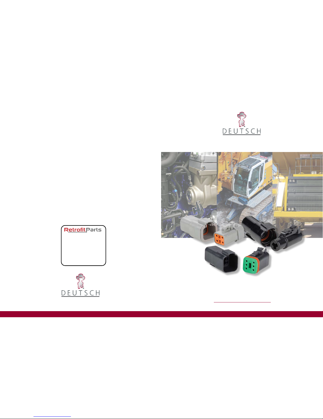
A STEP AHEADA STEP AHEAD
DT Series Technical Manual
INDUSTRIAL
3850 Industrial Avenue, Hemet, California 92545 Tel.: (951) 765-2250 - Fax: (951) 765-2255
Web: www.deutsch.net - Edition 2007
INDUSTRIAL
fu rn is h n ew c omp on en ts f or ol d
57 Milner Street
Newark
Nottinghamshire
NG24 4AA
T:01636 650778
www.retrotparts.co.uk
Page 2
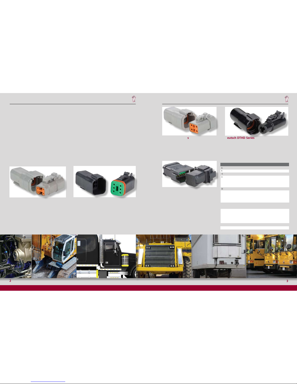
Table of Contents
Introduction
Features & Benefits
Product Line Overview
Material Specifications
General Specifications
Ordering Information
Insert Arrangements
Contacts & Application Data
2, 3
3
4
5
5
6
7, 8
9
DT Series Technical Manual
DT Series Technical Manual
A STEP AHEADA STEP AHEAD
Deutsch DTHD Series
Deutsch developed the DTHD Series for those applications
requiring a complete, environmentally sealed, single power circuit
termination. The plug features an integral coupling latch that
provides tactile and audible feedback during coupling. The rugged
thermoplastic receptacle is designed as an inline for cable to cable
applications and is supplied with an integral Vee-Groove to accept
mounting, clips, brackets and flanges.
Deutsch DT Bussed Series
2
3
Integral Connector Latch
Rugged Thermoplastic Housing
-55o C to +125o C Operating Temperature
Available Configurations:
DTM/DT 2, 3, 4, 6, 8 & 12 - Size 20/16
DTP 2 & 4 - Size 12
DTHD 1 - Size 4, 8 & 12
Silicone Seals:
DTM: Accepts AWG 22 - 16 wire
DT: Accepts AWG 20 - 14 wire
DTP: Accepts AWG 14 - 10 wire
DTHD: Accepts AWG 14 - 6 wire
Crimp Contacts with Option of Gold or Nickel
Finish, Solid or Stamped Construction
Current rating all contacts @ 1250 C no derating
DTM - 7.5 Amps
DT - 13 Amps
DTP - 25 Amps
DTHD - 25 to 100 Amps
Fail-Safe Secondary Locks All (Except DTHD)
Hand Insertable/Removable Contacts
Budget Minded
Tactile and Audible Assembly Feedback
Field Proven Long Service Life
Engine Compartment Rated
Meets Most Harness Design Requirements
Superior Environmental Seal
Seals on .053” to .120 dia.(1.35mm to 3.05mm)
Seals on .053” to .145 dia.(1.35mm to 3.68 mm)
Seals on .097” to .170 dia.(2.46mm to 4.32mm)
Seals on .134 to .292 dia. (3.40mm to 7.42mm)
Low Costs, High Reliability Terminals for Data &
Signal Transmission
Meets Most Signal Requirements
Positive Contact Retention
No Special Tools Required (Except DTHD)
Low Installation Costs
Features Benefits
Deutsch DTP Series
Deutsch’s DTP Series connectors are the answer to all of
your most demanding power application requirements.
DTP Series connectors offer the proven reliability and
quality of Deutsch’s DT Series, combined with the added
flexibilty of using power contacts.
Contact Retention System
Assembly Contact Insertion / Removal
Accessories
Shrink Boot Adaptor
Removal Tools / Sealing Plugs
DT Mounting Clips
Back Shells
10
11
12
12
12
13
14, 15
Deutsch DTM Series
Deutsch DTM Series of transportation connectors feature a
miniature contact with an enhanced design based on the
world class, field-proven Deutsch DT Series.
The DTM is the connector to be used in harsh environmental
application where reliable signal circuits are critical to
operating performance. Typical applications include on or
around the engine, the transmission and under the hood.
Environmentally-Sealed Transportation Connectors
Deutsch DT Series
An environmentally-sealed connector designed specifically for
cable to cable applications on the engine or transmission, under
the hood, on the chassis or in the cab. On signal level circuits in
harsh environmental conditions, where even a small degradation
in connection may be critical, the Deutsch DT Series general
purpose connectors will provide the reliability and performance
at the lowest cost.
Utilizing the Deutsch DT receptacle shell, Deutsch has
combined the rugged characteristics of the DT product
line with a bussing device allowing the elimination of
various harness splices. By using internal stamped bussed
contacts this product can be configured in whatever
arrangement meets your individual needs in the DT shell
size that matches your requirements. Complete bussing
flexibility in a compact, economical package.
Page 3
5
DT Series Technical Manual
DT Series Technical Manual
A STEP AHEAD
A STEP AHEAD
Product Line Overview
Deutsch DTM Series of transportation connectors feature a
miniature contact with an enhanced design based on the world
class, field-proven Deutsch “DT Series”.
The DTM is the connector to be used in harsh environmental
applications where reliable signal circuits are critical to operating
performance. Typical applications include on or around the
engine, the transmission and under the hood. In fact, everywhere
data signals or critical electronic circuits go, the field proven
Deutsch design of the DTM will provide reliable peak connector
performance.
The low cost, size 20 contacts terminate AWG 16 to 22 gauge
wire (0.5mm
2
to 1.5mm2). Closed entry socket (female) contacts
featuring spring action fingers are protected by a stainless steel
hood. This allows for positive axial alignment while mating and
prevents probe damage during testing.
Thermoplastic housings offer a wide operating temperature
range (-55
0
C to +125
0
C). Silicone rear wire and internal
peripheral interface seals allow the DTM to withstand moisture
and fluids.
Deutsch DT Series of environmentally-sealed, connectors are
designed specifically for cable to cable applications on the engine
or transmission, under the hood, on the chassis or in the cab.
Where signal level circuits in harsh environmental conditions,
where even a small degradation in connection may be critical,
the Deutsch DT Series general purpose connectors will provide
the reliability and performance at the lowest cost.
Thermoplastic (-55
0
C to + 1250 C rated) housings and silicone
seals are used to allow the connector to withstand conditions
of extreme temperature and moisture. The connector may be
employed with either solid-copper crimp type contacts for critical
circuits or budget-minded stamped and formed contacts. In
either selection, the spring action is designed in the socket and
shrouded by a stainless steel hood that provides closed entry for
positive axial alignment during mating, and eliminates probe
damage from occurring. Contact insertion and withdrawal require
no special tools and are retained in locked position by dielectic
fingers, molded as an integral part of the housing. Secondary
locks are assembled at the mating interfaces. If by chance the
secondary locks are not properly seated during assembly, they
will be pressed into locked position during the mating of the
connector.
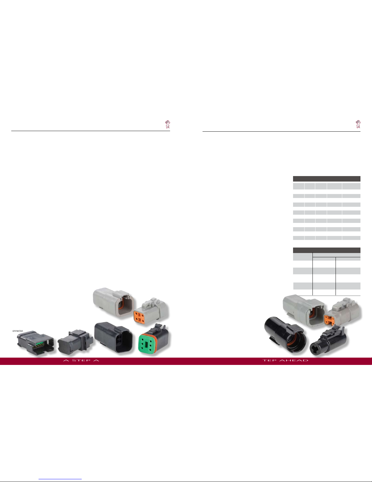
Deutsch DT Series
Deutsch DTM Series
These standard “DT” receptacle shells feature internal pin type
contact buss bar arrangements that allow common connections
from 3 to 12 size 16 contacts. Buss bars are available in standard
nickel or gold to match common Deutsch Industrial contacts.
Other features include the use of standard “DT” plugs to mate
with these environmental receptacles. Plugs with any Deutsch
modification are intermatable.
Deutsch DT Bussed Series
Deutsch DTP Series
Building on both the DT and DTM design strengths, the DTP
connector line was developed to fill the need for higher amperage,
multi-pin, inexpensive connectors. The series meets the same
specifications as the DTM and DT but offers the designer the ability
to use multiple 12 gauge contacts, each with a 25 amp continuous
capacity, within a single shell.
Based on the DTM overall design, it offers the protected interfacial
seal located within the receptacle shell. Standard multi-seal grommet
is used in both the plug and receptacle. Currently available in two and
four pin configurations.
Deutsch DTHD Series
Deutsch developed the DTHD Series for those applications requiring a
complete, environmentally sealed, single power circuit termination.
DTHD plugs and receptacles can be permanently assembled with
thermoplastic end caps that prevent removal of the silicone wire
seal grommets. Designed for diesel engine, electronic fuel injectors,
automatic transmissions, ABS brakes and other applications that
involve fuel and oil exposure. These end caps provide the additional
reliability required for critical wiring circuits.
4
Plug/Receptacle
Shell: Thermoplastic
Wedge: Thermoplastic
Grommet: Silicone Rubber
Contacts
Pin: Copper Alloy
Socket: Copper Alloy
Finish: Nickel (optional - gold) Plated
Sealing Plugs
Thermoplastic: (All sizes)
Dielectric Withstanding Voltage
Current leakage less than 2 milliamps at 1500 VAC
Insulation Resistance:
1000 megohms minimum at 25
0
C.
Current Rating (Contact current rating @ 125
0
C (continuous)
Size 20: 7.5 amps
Size 16: 13 amps
Size 12: 25 amps
Size 8: 60 amps
Size 4: 100 amps
Submersion:
Properly wired and mated connection will withstand immersion under
three feet of water without loss of electronic qualities or leakage.
Fluid Resistance:
Connectors show no damage when exposed to most fluids used in
industrial applications.
Vibration:
No unlocking or unmating and exhibits no mechanical or physical
damage after sinusoidal vibration levels of 20 G’s at 10 to 2000
Hz in each of the three mutually perpendicular planes. No electrical
discontinuities longer than 1 microsecond.
Temperature:
Operative at temperatures from -55
0
C to +1250C. Continuous at rated
current.
Contact Retention:
Contacts withstand a minimum load of:
20 lbs (89N) for size 20
25 lbs (111N) for size 16
30 lbs (133N) for size 12
35 lbs (156N) for size 8
35 lbs (156N) for size 4
MATERIAL SPECIFICATIONS
GENERAL SPECIFICATIONS
Thermal Cycle:
No cracking, chipping or leaking after 20 test cycles from
-55
0
C to +1250 C.
Durability:
No electrical or mechanical defects after 100 cycles of
engagement and disengagement.
CONTACT RESISTANCE
CONTACT
SIZE
WIRE GAUGE
AWG(mm
2
)
Test Current
(Amps)
Resistance (mV)
Solids
Resistance (mV)
Stamped & Formed
18 (.80)
16 (1.0)
20 (.50)
16 (1.0)
20
7.5
60
100
13
60
100
13
60
100
7.5
60
100
7.5
60
100
10
60
100
16
20 (.50)
14 (2.0)
18 (.80)
7.5
60
100
14 (2.0)
12 (3.0)
12
18
60
100
25
60
100
8
4
8 (8.60)
10 (5.60)
60
N/A
60
N/A
6 (13.0)
60
N/A
60
60
100
CONTACT SIZE
N-SEAL
#20
#16
#12
#8
#4
E-SEAL
.280-.292
(7.11-7.42)
.134-.170
(3.40-4.32)
N/A
.190-.240
(4.83-6.10)
N/A
.097-.158
(2.46-4.01
)
.088-.145
(2.24-3.68)
.053-.120
(1.35-3.05)
.053-.120
(1.35-3.05)
N/A
RECOMMENDED WIRE INSULATION O.D.
WIRE SEALING RANGE
Page 4
DT Series Technical Manual
DT Series Technical Manual
A STEP AHEAD
A STEP AHEAD
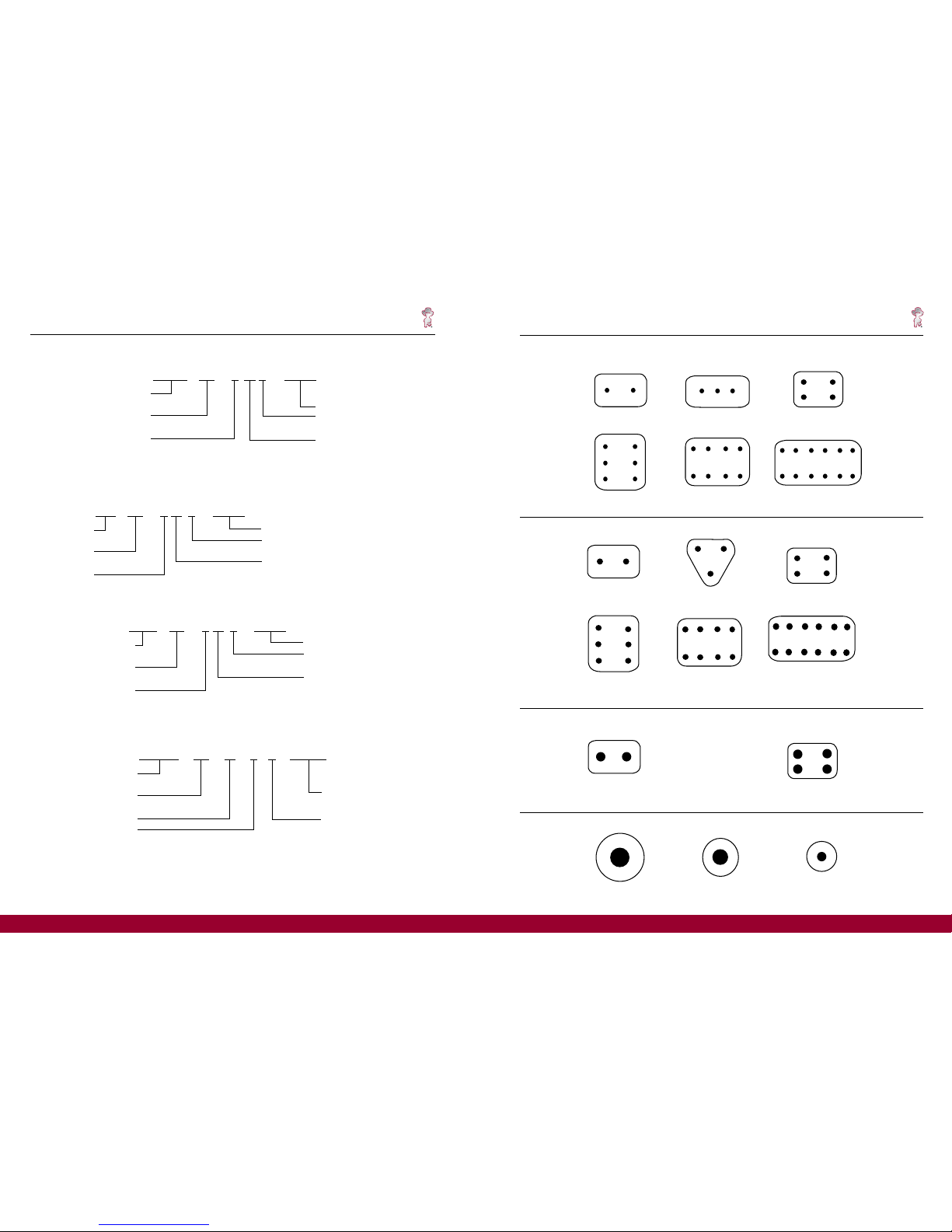
DTM Series Size 20 Contacts
DT & DT BUSSED Series Size 16 Contacts
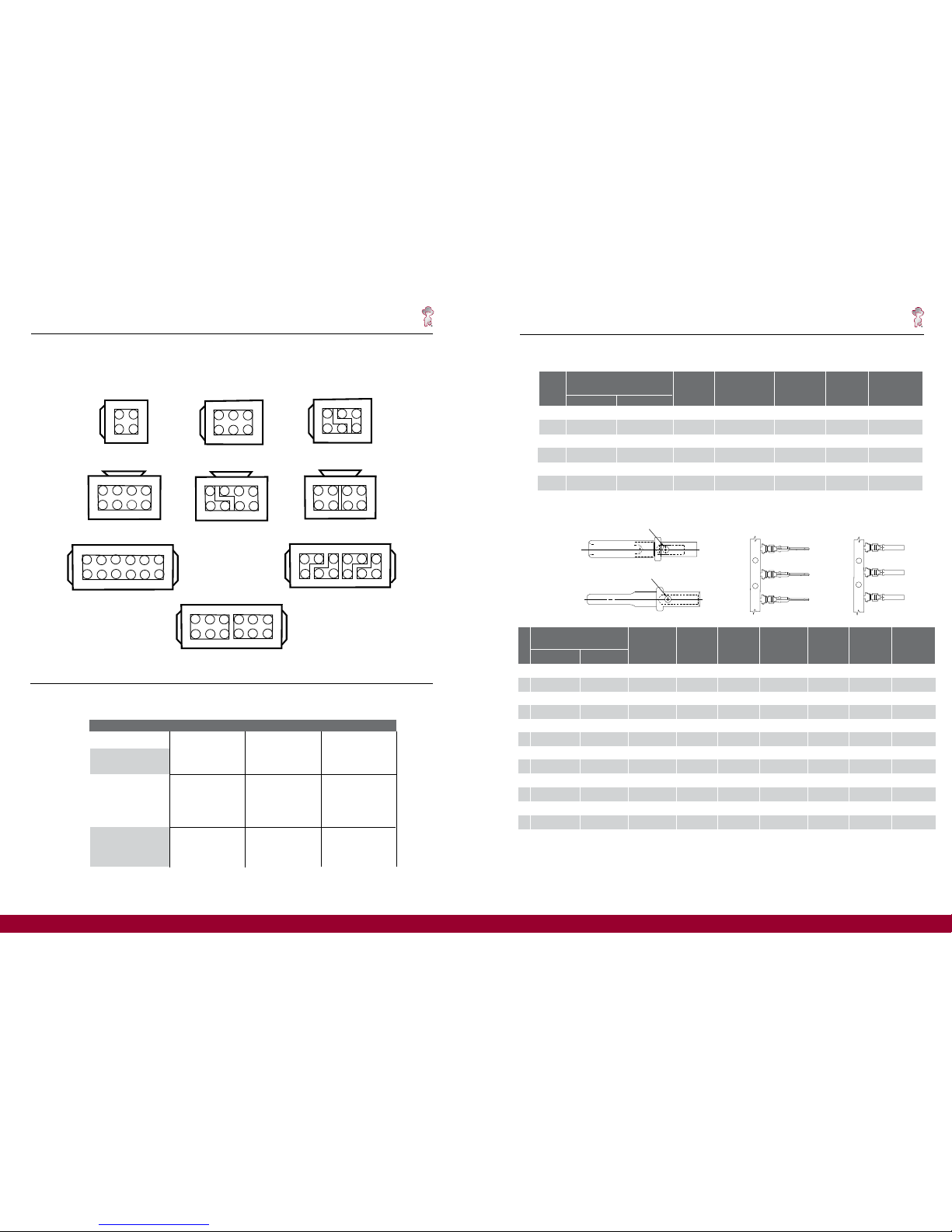
2
2 size 16
3
3 size 16
4
4 size 16
6
6 size 16
8
8 size 16
12
12 size 16
DTP Series Size 12 Contacts
2
2 size 12
4
4 size 12
2
2 size 20
3
3 size 20
4
4 size 20
8
8 size 20
6
6 size 20
12
12 size 20
6
7
DTHD Series Size 4, 8 & 12
1
1 size12
1
1 size 4
1
1 size 8
PART NUMBERING SYSTEM (DTHD)
DTHD 06 - 1 - 4 S - ****
Series Prefix
04 = Receptacle
06 = Plug
Single Terminal
Contact Size
4 = Size 4
8 = Size 8
12 = Size 12
Contact Style
P = Pin Receptacle Only
S = Socket Plug Only
Special Modifications
PART NUMBERING SYSTEM (DTM)
DTM 06 - 2 S * - ****
Series Prefix
04 = Receptacle
06 = Plug
Number of Contacts
Special Modifications
Polarizing Position (If Applicable)
08 + 12 Only
Contact Type
P = Pin Receptacle Only
S = Socket Plug Only
PART NUMBERING SYSTEM (DT & DT Bussed)
DT 06 - 2 S * - ****
Series Prefix
04 = Receptacle
06 = Plug
Number of Contacts
Special Modifications
Polarizing Position
(If Applicable)
Contact Type
P = Pin Receptacle Only
S = Socket Plug Only
PART NUMBERING SYSTEM (DTP)
DTP 06 - 2 S * - ****
Series Prefix
04 = Receptacle
06 = Plug
Number of Contacts
Special Modifications
Polarizing Position
(If Applicable)
Contact Type
P = Pin Receptacle Only
S = Socket Plug Only
Page 5
9
CONTACTS AND APPLICATION DATA
Solid Contacts
** For proper dies and stamped & formed crimp dimensions - See Envelope 0425-208-0000 12 Size Consult factory for alternate finishes
0425-203-0000 16 Size
0425-207-0000 20 Size
0425-059-0000 16,20 Size
0425-039-0000 16 Size
0425-041-0000 12 Size
1060-20-01** 1062-20-01**
1060-20-02** 1062-20-02**
N/A 1062-20-03**
1060-14-01** 1062-14-01**
1060-14-10** 1062-14-10**
1060-16-01** 1062-16-01**
1060-16-06** 1062-16-06**
1060-16-07** 1062-16-07**
1060-16-09** 1062-16-09**
1060-16-12** 1062-16-12**
N/A 1062-16-14**
1060-12-01** 1062-12-01**
1060-12-02** 1062-12-02**
STAMPED & FORMED CONTACT
PART NUMBERS
SIZE
20
20
20
16
16
16
16
16
16
16
16
12
12
PIN
SOCKET
20 - 01
20 - 02
20 - 03
14-16
14 -16
16 - 18
0.5 - 1.0
0.75 - 2.0
16 - 18
1.0 - 2.5
14 - 16
12 - 14
10 - 12
CARRIER
STRIP
IDENTIFICATION
WIRE SIZE
AWG (mm2)
16 - 22
(1.0 - 0.35)
16 - 22
(1.0 - 0.35)
16 - 22
(1.0 - 0.35)
14 - 18
(2.0 - .75)
14 - 18
(2.0 - .75)
14 - 18
(2.0 - .75)
16 - 20
(1.0 - 0.50)
14 - 18
(2.0 - .75)
14 - 18
(2.0 - .75)
12 - 16
(2.5 - 1.0)
12 - 16
(2.5 - 1.0)
12 - 14
(4.0 - 2.0)
10 - 12
(6.0 - 4.0)
WIRE
INSULATION
O.D. RANGE
.075 - .125
(1.91 - 3.15)
.051 - .085
(1.30 - 2.16)
.075 - .125
(1.91 - 3.15)
.095 - .150
(2.41 - 3.81)
.095 - .150
(2.41 - 3.81)
.075 - .140
(1.91 - 3.55)
055 - .100
(1.40 - 2.54)
.075 - .140
(1.91 - 3.55)
.075 - .140
(1.91 - 3.55)
.075 - .140
(1.91 - 3.55)
.075 - .140
(1.91 - 3.55)
.113 - .176
(2.87 - 4.47)
.140 - .204
(3.56 - 5.18)
.150 - .200
(3.81 - 5.08)
.150 - .200
(3.81 - 5.08)
.150 - .200
(3.81 - 5.08)
.150 - .200
(3.81 - 5.08)
.150 - .200
(3.81 - 5.08)
.150 - .200
(3.81 - 5.08)
.150 - .200
(3.81 - 5.08)
.150 - .200
(3.81 - 5.08)
.150 - .200
(3.81 - 5.08)
.175 - .225
(4.45 - 5.72)
.175 - .225
(4.45 - 5.72)
.225 - .275
(5.72 - 6.991)
.225 - .275
(5.72 - 6.99)
MIN CONT.
RETENTION
LBS (N)
20
(89)
20
(89)
20
(89)
25
(111)
25
(111)
25
(111)
25
(111)
25
(111)
25
(111)
25
(111)
25
(111)
30
(134)
30
(134)
REF CRIMP
TENSILE
LBS (N)
20 - 10
(89 - 45)
20 - 10
(89 - 45)
20 - 10
(89 - 45)
25
(111)
25
(111)
25
(111)
25 - 15
(111 - 67)
25
(111)
25
(111)
25
(111)
25
(111)
70
(311)
70
(311)
MAX RATED
AMPS AT 125
0
C
CONTINUOUS
7.5
7.5
7.5
13
13
13
13
13
13
13
13
25
25
RECOMMENDED
STRIP LENGTH
INCHES (mm)
Stamped & Formed Contacts
INSPECTION HOLE
Solid Contacts Stamped and Formed Contacts
Socket
Pin
Pin
Socket
INSPECTION HOLE
* See Envelope Print 0425-205-0000. Consult factory for alternate finishes.
SIZE
SOLID CONTACT
PART NUMBERS
WIRE SIZE
AWG (mm
2
)
RECOMMENDED
STRIP LENGTH
INCHES (mm)
MIN CONTACT
RETENTION
LBS (N)
REF CRIMP
TENSILE
LBS (N)
MAX RATED
AMPS AT 125
0
C
CONTINUOUS
PIN SOCKET
20
16
16
12
8
4
20
(0.50)
14
(2.0)
16-20
(1.0 - 0.50)
12-14
(3.0 - 2.0)
.156-.218
(3.96 - 5.54)
.250 - .312
(6.35 - 7.92)
.250 - .312
(6.35 - 7.92)
.222 - .284
(5.64 - 7.21)
20
(89)
25
(111)
25
(111)
30
(134)
20
(89)
70
(311)
35-20
(156-89)
75-70
(334 - 311)
7.5
13
13
25
6
(13.0)
8-10
(8.0 - 5.0)
.430-.492
(10.92-12.50)
.430 - .492
(10.92 - 12.50)
35
(156)
35
(156)
300
(1334)
100
125-90
(556-400)
60
0460-202-20** 0462-201-20**
0460-202-16** 0462-201-16**
0460-215-16** 0462-209-16**
0460-204-12** 0462-203-12**
0460-204-08** 0462-203-08**
0460-204-04** 0462-203-04**
DT Series Technical Manual
DT Series Technical Manual
A STEP AHEAD
A STEP AHEAD
DT Series BUSSED Arrangements
12 PIN
DEUTSCH
10911
12 7
8
3
4
21
6
5
6
7
10911
12
3
4215
8
DEUTSCH
12 PIN
DEUTSCH
10911
12 7
8
3
4
21
6
5
12 PIN
DEUTSCH
1
2
6
5
4
3
7
8
8 PIN
DEUTSCH
1
2
6
5
4
3
7
8
8 PIN
6
5
7
8
1
2
4
3
DEUTSCH
8 PIN
1 4
2 3
DEUTSCH
4 PIN
6 PIN
DEUTSCH
1
2
6
5
4
3
DEUTSCH
1
2
6
5
4
3
6 PIN
MAX CURRENT RATINGS
NICKEL BUSS P/N
DT04-4P-EP12
DT04-6P-EP12
DT04-6P-EP15
DT04-8PB-P016
DT04-8PB-PO29
DT04-8PB-P027
DT04-3P-***
DT04-12PB-P016
DT04-12PB-P027
DT04-12PB-P031
GOLD BUSS P/N
DT06-4S-****
DT06-6S-****
DT06-6S-****
DT06-08SB-****
DT06-08SB-****
DT06-08SB-****
DT06-3S-****
DT06-12SB-****
DT06-12SB-****
DT06-12SB-****
MATING PLUG P/N
DT04-4P-EP13
DT04-6P-EP13
DT04-6P-EP14
DT-8PB-P021
DT04-8PB-PO28
DT04-8PB-P026
DT04-3P-***
DT04-12PB-P021
DT04-12PB-P026
DT04-12PB-P030
4 PIN = 26 AMPS
6 PIN = 39 AMPS
3 PIN = 13 AMPS
8 PIN = 52 AMPS
5 PIN = 26 AMPS
4 PIN = 26 AMPS
3 PIN = 13 AMPS
12 PIN = 76 AMPS
6 PIN = 39 AMPS
3 PIN = 13 AMPS
ALL PART NUMBERS ARE
FOR “BLACK”
PLEASE CONSULT FACTORY FOR AVAILABILITY AND ALTERNATE KEYING
Arrangements shown are currently available. For additional arrangements contact factory.
8
Standard DT Receptacles Bussed to Customer Specifications
Page 6
DT Series Technical Manual
A STEP AHEADA STEP AHEAD
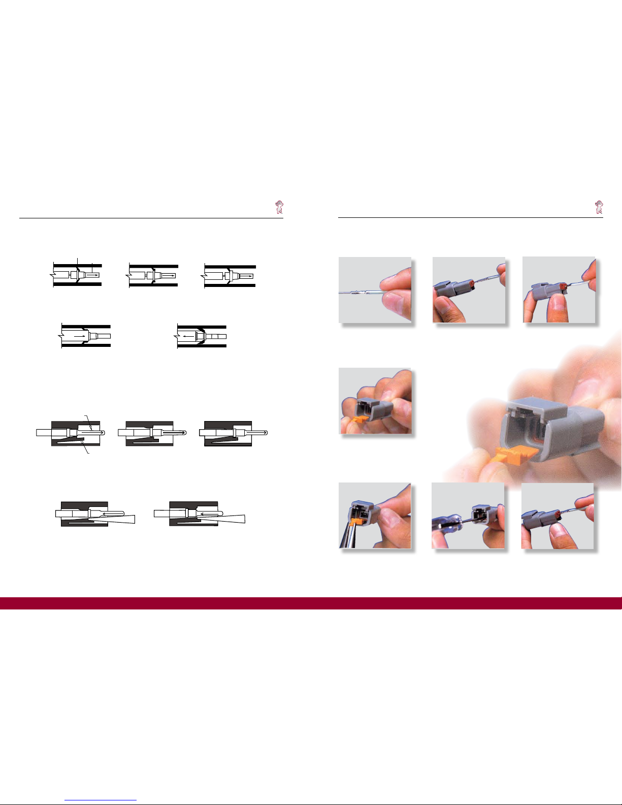
Assembly Contact Insertion (DTM, DT, DTP)
Contact Removal
1. Grasp crimped contact
approximately 1.0” (25.4mm)
behind the contact barrel.
2. Hold connector with rear
grommet facing you.
3. Push contact straight into
connector grommet until a click
is felt. A slight tug will confirm
that it is properly locked in
place.
4. Once all contacts are in place,
insert orange wedge: receptacles
- with half holes aligning with
contacts. Plugs - with contacts
aligning behind full holes. The
orange wedge will snap into
place.
1. Remove orange wedge using
needlenose pliers to pull wedge
straight out.
2. To remove the contacts,
gently pull wire backwards,
while at the same time releasing
the locking finger by moving it
away from the contact with a
screwdriver.
3. Hold the rear seal in place,
as removing the contact will
displace the seal.
10
11
NOTE: The receptacle is shown
- use the same procedure for
plug.
DT Series Technical Manual
Contact Retention System (DTHD)
Rquired Removal Tool (See page 12)
TOOL AND CONTACT REMOVED
Contact Insertion Procedure
UNLOCKED POSITION
CONTACT INSERTION
LOCKING FINGERS
CONTACT
CONTACT LOCKED POSITION
TOOL INSERTED TO UNLOCK CONTACT
SCREW DRIVER INSERTED TO UNLOCK CONTACT
CONTACT REMOVED
CONTACT LOCKED IN POSITION
UNLOCKED POSITION
Contact Removal Procedure (DTM/DT/DTP)
Contact Insertion System (DTM/DT/DTP)
CONTACT INSERTION
CONTACT
LOCKING FINGER
Page 7
A STEP AHEADA STEP AHEAD
DT Series Technical Manual Accessories
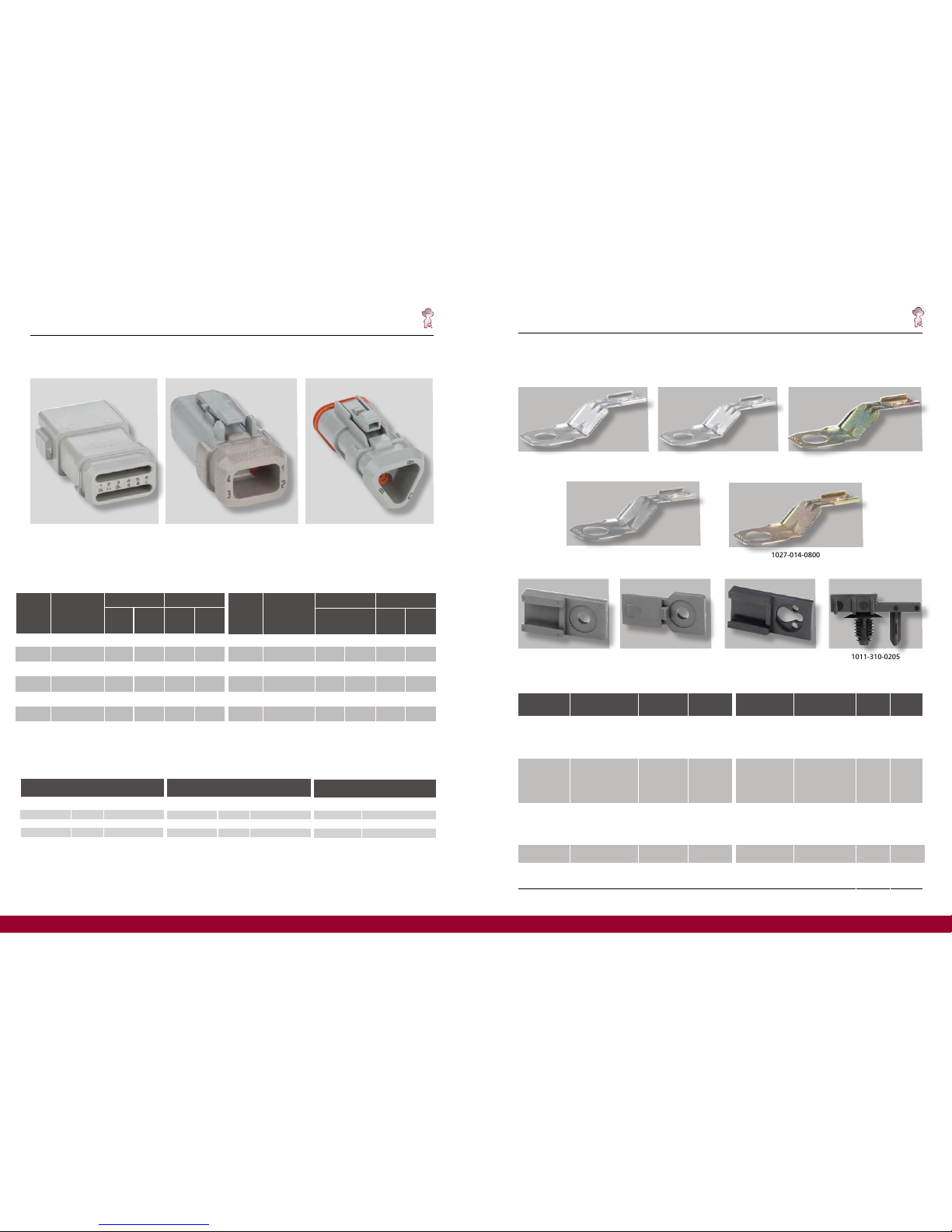
Accessories
To meet the application requirements where wires are to be protected, the DT Series may be supplied with boot adaptors. These
will accept shaped boots / sleeves or shrink tubing. Parts for standard or thin wall wire are available.
12
Shrink Boot Adaptor Modification Numbers
Part Number - Plugs
Part Number - Receptacles
PART NO.
NORMAL WIRE SEALS (N)
12
8
4
WIRE RANGE AWG
SIZE
114010
114008
114009
12-14
8-10
6
PART NO.
EXTRA THIN WALL WIRE SEALS (E)
12
8
4
WIRE RANGE AWG
SIZE
0411-337-1205
0411-353-0805
114009
12-14
8-10
6
CONTACT SIZE
SEALING PLUG
PART NO.
20
16 -12
8
4
0413-204-2005
114017
114018
114019
DTHD Removal Tools
Sealing Plugs
2
3
4
6
8
12
DT06-2S
DT06-3S
DT06-4S
DT06-6S
DT06-8SA
DT06-12SA
-E008
-E008
-E008
-E008
-E008
-E008
-CE04
-CE04
-CE04
-CE04
-CE04
-CE04
-EP11
-EP11
-EP11
-EP11
-EP11
-EP11
-CE13
-CE13
-CE13
-CE13
-CD13
-CD13
Number
of
Ways
Black
Grey
Basic
Part Number
Std.
Thin
Wall
Std.
Number
of
Ways
Black
Grey
Basic
Part Number
Std.
Thin
Wall
Std.
2
3
4
6
8
12
DT04-2P
DT04-3P
DT04-4P
DT06-6P
DT04-8PA
DT04-12PA
-E008
-E008
-E008
-E008
-E008
-E008
-CE04
-CE04
-CE04
-CE04
-CE04
-CE04
-EE11
-EE11
-EE11
-EE11
-EE11
-EE11
-CE09
-CE09
-CE09
-CE09
-CE09
-CE09
Wire Sealing Range: Standard - 2.24mm - 3.68mm wire insulation diameter Thin wall - 1.35mm - 3.05mm wire
insulation diameter
Thin
Wall
Thin
Wall
DT Series Technical Manual Accessories
13
1027-003-1200
1011-026-0205
(Thru Hole)
1027-014-0800
1027-001-0800 1027-004-1200
1027-005-1200
1011-030-0205
(Snap Fit)
1011-027-0805
(Thru Hole)
DT Mounting Clips
Metal Mounting Clips
Metal Mounting Clips
Plastic Mounting Clips
1027-003-1200
1027-005-1200
1027-004-1200
1027-001-0800
1027-014-0800
Part Number
Used On Material
DTM (all)
DT 2, 3, 4, 6, 12
DTP (all)
DTHD (all)
DTM (all)
DT 2, 3, 4, 6, 12
DTP (all)
DTHD (all)
DTM (all)
DT 2, 3, 4, 6, 12
DTP (all)
DTHD (all)
DT 8 cavity only
DT 8 cavity only
Stainless Steel
Stainless Steel
Stainless Steel
w/Zinc Plating
Stainless Steel
Stainless Steel
w/Zinc Plating
.433 (11.0)
.512 (13.0)
.512 (13.0)
.433 (11.0)
.323 (8.2)
Hole O.D.
in. (mm)
1011-026-0205
1011-027-0805
1011-027-0805
Plastic
Plastic
Plastic
Gray
Gray
Black
Part Number
DTM (all)
DT 2, 3, 4, 6, 12
DTP (all)
DTHD (all)
DT 8 Cavity Only
DTM (all)
DT 2, 3, 4, 6, 12
DTP (all)
DTHD (all)
Used On
Material Color
1011-310-0205
(W/Self Mounting Stud)
 Loading...