

Dettson C45-1-D, C105-1-D, C75-1-D, C45-2-D, C60-2-D Installation Manual And User's Manual
...
ATTENTION: Do not tamper with the unit or its controls. Call a qualified service technician.
INSTALLER / SERVICE TECHNICIAN: Use the information in this manual for the installation / servicing of the furnace and
These instructions must be read and understood completely before attempting installation.
HOMEOWNER: PLEASE Keep this manual nears the furnace for future reference.
Manufactured by:
Industries Dettson Inc.
Sherbrooke (Québec) Canada
www.dettson.com
2015-07-09 X40223 rev. I
keep the document near the unit for future reference.

TABLE OF CONTENT
1- Safety regulation .............................................. 5
1.1- Safety labeling and warning signs ................ 5
1.2- Important information ................................... 5
1.3- Detection systems ........................................ 5
2- Introduction ....................................................... 7
2.1- Codes and standards ................................... 8
2.1.1- Safety ............................................................ 8
2.1.2- General installation ........................................ 8
2.1.3- Combustion and air ventilation....................... 8
2.1.4- Duct systems ................................................. 8
2.1.5- Acoustical lining and fibrous glass duct ......... 8
2.1.6- Gas piping and pipe pressure testing ............. 8
2.1.7- Electrical connections .................................... 8
2.2- Electrostatic discharge ................................. 8
2.3- Location ....................................................... 8
2.3.1- Location relative to cooling equipment ........... 9
2.4- Introduction .................................................. 9
2.4.1- Direct vent (2 pipes applications) ................... 9
2.4.2- Non direct vent (1 pipe) applications ............ 10
2.4.3- Ventilated combustion air applications ......... 10
2.5- Connecting to furnace ................................ 10
2.5.1- Combustion air piping .................................. 11
2.5.2- Exhaust vent piping ..................................... 11
3- Installation ....................................................... 11
3.1- Upflow orientation ...................................... 12
3.1.1- Right side condensate drain connection ...... 13
3.1.2- Left side condensate drain connection ......... 13
3.2- Down flow orientation ................................. 13
3.2.1- Down flow condensate drain connection ...... 13
3.2.2- Downflow venting drainaged ........................ 13
3.2.3- Condensate box pressure switch ................. 13
3.3- Horizontal right orientation ......................... 13
3.3.1- Horizontal right condensate drain
connection ................................................................. 13
3.3.2- Horizontal right vent drainage ...................... 14
3.3.3- Condensate box pressure switch ................. 14
3.4- Horizontal left orientation ........................... 14
3.4.1- Horizontal left condensate drain connection 14
3.4.2- Condensate box pressure switch ................. 15
4- Duct installation .............................................. 15
4.1- Return air connections ............................... 15
4.1.1- Bottom return air inlet .................................. 15
4.1.2- Side return air inlet ...................................... 15
4.2- Filter arrangement ...................................... 15
4.3- Supply air ducts ......................................... 15
4.4- General requirements ................................ 15
4.4.1- Duct work acoustical treatment .................... 16
5- Gas piping ....................................................... 17
5.1- Gas pipe grommet ..................................... 18
6- Electrical connections ................................... 18
6.1- 120 V wiring ............................................... 18
6.2- 24 V wiring ................................................. 19
6.3- Thermostats ............................................... 19
6.4- Alternate power supply .............................. 19
6.5- blower speeds (4 speed PSC motor) ......... 19
7- Venting ............................................................. 23
7.1- Special venting requirements for installations
in canada ................................................................. 23
7.2- General ...................................................... 23
7.3- Materials .................................................... 23
7.4- Direct vent - 2 pipes system ....................... 23
7.5- Size of the vent and combustion air pipes . 23
7.6- Combustion air and vent piping insulation
guidelines ................................................................ 26
7.7- Installing the vent termination .................... 27
7.7.1- Concentric vent ........................................... 27
7.7.2- Two pipes termination ................................. 27
7.7.3- Sidewall termination .................................... 27
8- Start up, adjustment and safety check ......... 27
8.1- To start the furnace .................................... 27
8.2- Unit operation hazard ................................. 28
8.3- Setup switches ........................................... 28
8.4- Option switches – 1 stage, PSC ................. 28
8.4.1- Heat mode .................................................. 28
8.4.2- Cool mode ................................................... 28
8.4.3- Manual fan on mode .................................... 29
8.4.4- Twinning interface ....................................... 29
8.4.5- System lockout and diagnostic features ....... 29
8.4.6- System lockout features .............................. 29
8.4.7- Diagnostic features ...................................... 29
8.5- Option switches – 2 stage, PSC ................. 29
8.5.1- Heat mode .................................................. 29
8.5.2- Cool mode ................................................... 30
8.5.3- Manual fan on mode .................................... 30
8.5.4- Twinning interface ....................................... 30
8.5.5- System lockout and diagnostic features ....... 30
8.5.6- System lockout ............................................ 30
8.5.7- Last fault mode ............................................ 30
8.5.8- Fault code reset .......................................... 30
8.5.9- Diagnostic features ...................................... 30
8.6- Option switch settings – 2 stage ECM........ 32
8.6.1- Thermostat type and heat-fan-off delay ....... 32
8.6.2- Multi-stage thermostat set-up, factory
default 32
8.6.3- Single stage thermostat set-up, module
controls staging ......................................................... 32
8.6.4- Heat fan off delay timing .............................. 32
8.6.5- De-humidification connection ....................... 32
8.6.6- Normal operation – heat on ......................... 32
8.6.7- Normal operation – heat off ......................... 32
8.6.8- Cool mode ................................................... 32
8.6.9- Adjust cooling airflow – dipswitch S3-1 and
S3-2 32
8.6.10- Manual fan on mode ............................... 32
8.7- Troubleshooting ......................................... 33
8.7.1- System lockout ............................................ 33
8.7.2- System reset ............................................... 33
8.7.3- Thermostat reset ......................................... 33
8.7.4- Auto restart ................................................. 33
8.7.5- Diagnostic features ...................................... 33
8.7.6- Fault code retrieval ...................................... 33
8.7.7- CFM indicator .............................................. 33
8.8- Prime condensate trap with water .............. 35
8.8.1- Check safety controls .................................. 35
8.8.2- Checklist ..................................................... 35
9- Operating your furnace .................................. 35
9.1- Start up instructions ................................... 35
9.2- Shutting down the furnace ......................... 35
9.2.1- To turn off gas to furnace ............................ 35
10- Maintenance of your furnace .................. 36
10.1- Cleaning/replacing the filter ........................ 36
10.1.1- Filter location .......................................... 36
10.2- Lubrication ................................................. 36
10.3- Burner flame .............................................. 36
10.4- Condensate collection and disposal system
(if applicable) ........................................................... 36
10.5- Rollout switch ............................................. 36
10.6- Safety interlock switch................................ 36
10.7- repair parts ................................................. 36
2

INDEX OF FIGURES
Figure 1 Freeze protection and return air temp. ............... 8
Figure 2 Installation in a garage ....................................... 9
Figure 3 Prohibited installation ......................................... 9
Figure 4 Dimensional drawing ........................................ 10
Figure 5 Vent coupling and adapter with gaskets ........... 11
Figure 6 Vent termination ............................................... 11
Figure 7 Drain Trap ........................................................ 12
Figure 8 Left side condensate drain connection ............. 12
Figure 9 Right side condensate drain connection .......... 12
Figure 10 : Down flow orientation ................................... 13
Figure 11 Condensate pressure switch .......................... 13
Figure 12 Horizontal right drain trap position .................. 14
Figure 13 Horizontal right condensate tubing ................. 14
Figure 14 Pressure switch assembly .............................. 14
Figure 15 Horizontal left condensate drain connection .. 15
INDEX OF TABLES
Figure 16 Return air base ............................................... 15
Figure 17 Typical gas pipe arrangement ........................ 17
Figure 18 Power cord installation in the furnace ............ 19
Figure 19 Wiring diagram – One stage PSC .................. 20
Figure 20 : Two Stage PSC - Furnace Control ............... 21
Figure 21 : Two Stage ECM - Furnace Control .............. 22
Figure 22 Direct venting ................................................. 24
Figure 23 Multi venting ................................................... 25
Figure 24 Control Switch – Modulating Valve ............ 35
Figure 25 Typical Flame Appearance ........................ 36
Figure 26 Exploded view 1 stage PSC ........................... 37
Figure 27 Exploded view 2 stage PSC ........................... 40
Figure 28 Exploded view 2 stage ECM .......................... 43
Table 1 Minimum clearance to combustible material for all
units.................................................................................. 9
Table 2 Loose parts list .................................................... 9
Table 3 Air flow capacity and blower data 2 stage
variable........................................................................... 16
Table 4 : Air flow capacity and blower data 2 stage direct
drive ............................................................................... 16
Table 5 : Air flow capacity and blower date 1 stage direct
drive ............................................................................... 17
Table 6 Maximum capacity of pipe in Ft³ of gas/hr ......... 17
Table 7 Gas pressure ..................................................... 17
Table 8 Electrical data .................................................... 18
Table 9 : Suggested fan speed on 1 stage furnace ........ 19
Table 10 : Suggested fan speed on 2 stage furnace ...... 19
Table 11 : Maximum equivalent straight vent length (two
stage and modulating) .................................................... 25
Table 12 Maximum equivalent straight vent length (single
stage) ............................................................................. 25
Table 13 Deduction for fitting ......................................... 26
Table 14 Approved combustion air and vent pipe, fitting
and cement materials (U.S.A. Installation) ..................... 26
Table 15: Option switches positions........................... 28
Table 16: Option switches S1-3 & S1-4 positions ...... 29
Table 17: Option switches S1-1 & S1-2 positions ...... 29
Table 18: Duty cycles ................................................. 29
Table 19: DIP Switches .............................................. 32
Table 20: Duty cycle .................................................. 32
Table 21: DIP Switches .............................................. 32
Table 22 : Dipswitch setting for airflow selection ............ 32
Table 23 Part list - 1 stage PSC ..................................... 39
Table 24: Part list – 2 Stage, PSC ............................. 42
Table 25: Part list – 2 Stage, ECM ............................. 45
Table 26 CFM for 45,000 BTU PSC motor ..................... 46
Table 27 CFM in heating for 45,000 BTU 2 stage ECM
motor .............................................................................. 46
Table 28 CFM in cooling for 45,000 BTU 2 stage ECM
motor .............................................................................. 46
Table 29 CFM for 60,000 BTU PSC motor ..................... 47
Table 30 CFM in heating for 60,000 BTU 2 stage ECM
motor .............................................................................. 47
Table 31 CFM in cooling for 60,000 BTU 2 stage ECM
motor .............................................................................. 47
Table 32 CFM for 75,000 BTU PSC motor ..................... 48
Table 33 CFM in heating for 75,000 BTU 2 stage ECM
motor .............................................................................. 48
Table 34 CFM in cooling for 75,000 BTU 2 stage ECM
motor .............................................................................. 48
Table 35 CFM for 105,000 BTU PSC motor ................... 49
Table 36 CFM in heating for 105,000 BTU 2 stage ECM
motor .............................................................................. 49
Table 37 CFM in cooling for 105,000 BTU 2 stage ECM
motor .............................................................................. 49
Table 38 CFM for 120,000 BTU PSC motor ................... 50
Table 39 CFM in heating for 120,000 BTU 2 stage ECM
motor .............................................................................. 50
Table 40 CFM in cooling for 120,000 BTU 2 stage ECM
motor .............................................................................. 50
Table 41 2 stage variable speed gas furnace (ECM) ..... 51
Table 42 2 Stage fixed speed gas furnace (PSC) .......... 51
Table 43 1 Stage fixed speed gas furnace (PSC) .......... 51
Table 44 Maximum equivalent straight vent length for 1
stage unit (1-D) .............................................................. 51
Table 45 Maximum equivalent straight vent length for
modulating and 2 stage unit (M-V;2-D and 2-V) ............. 51
ANNEX I : CFM TABLES ......................................................................................................................................................... 46
ANNEX II : SPECIFICATION SHEET....................................................................................................................................... 51
INDEX OF ANNEXES
3

REQUIRED NOTICE FOR MASSACHUSETTS INSTALLATIONS
IMPORTANT
The Commonwealth of Massachusetts requires compliance with regulation 248 CMR as follows:
5.08: Modifications to NFPA-54, Chapter 10. Revise 10.8.3 by adding the following additional requirements:
For all side wall horizontally vented gas fuelled equipment installed in every dwelling, building or structure used in whole or in part for residential
purposes, including those owned or operated by the commonwealth and where the side wall exhaust vent termination is less than seven (7)
feet above finished grade in the area of the venting, including but not limited to decks and porches, the following requirements shall be satisfied:
Installation of Carbon Monoxide Detectors
At the time of installation of the side wall horizontal vented gas fuelled equipment, the installing plumber or gas fitter shall observe that a hard
wired carbon monoxide detector with an alarm and battery backup is installed on the floor level where the gas equipment is to be installed. In
addition, the installing plumber or gas fitter shall observe that a battery operated or hard wired carbon monoxide detector with an alarm is
installed on each additional level of the dwelling, building or structure served by the side wall horizontal vented gas fuelled equipment. It shall
be the responsibility of the property owner to secure the services of qualified license professionals for the installation of hard wired carbon
monoxide detectors.
In the event that the side wall horizontally vented gas fuelled equipment is installed in a crawl space or an attic, the hard wired carbon monoxide
detector with alarm and battery backup may be installed on the next adjacent floor level.
In the event that the requirements of this subdivision cannot be met at the time of completion of installation, the owner shall have a period of
thirty (30) days to comply with the above requirement; provided, however, that during said thirty (30) day period, a battery operated carbon
monoxide detector with an alarm shall be installed.
APPROVED CARBON MONOXIDE DETECTORS: Each carbon monoxide detector as required in accordance with the above provision shall
comply with NFPA 720 and be ANSI/UL 2034 listed and IAS certified.
SIGNAGE: A metal or plastic identification plate shall be permanently mounted to the exterior of the building at a minimum height of eight (8)
feet above grade directly in line with the exhaust vent terminal for the horizontally vented gas fuelled heating appliance or equipment. The sign
shall read, in print size no less than in-half (1/2) inch in size, “gas vent directly below. Keep clear of all obstruction”.
INSPECTION: the state of local gas inspector of the side wall horizontally vented gas fuelled equipment shall not approve the installation
unless, upon inspection, the inspector observes carbon monoxide detectors and signage installed in accordance with the provisions of 248
CMR 5.08 (2) (a) 1 through 4:
EXEMPTION: the following equipment is exempt from 248 CMR 5.08(2) (a) 1 through 4:
The equipment listed in Chapter 10 entitled “equipment not required to be vented “in the most current edition of NFPA 54 as adopted by the
board; and
Product approved side wall horizontally vented gas fuelled equipment installed in a room or structure separate from the dwelling, building or
structure in whole or in part for residential purposes.
MANUFACTURER REQUIREMENTS – GAS EQUIPMENT VENTING SYSTEM PROVIDED
When the manufacturer of product approved side wall horizontally vented gas equipment provides a venting system design or venting system
component with the equipment, the instructions provided by the manufacturer for installation of the equipment and the venting system shall
include:
Detailed instructions for the installation of the venting system design or the venting system components; and a complete parts list for the
venting system design or venting system.
MANUFACTURER REQUIREMENTS – GAS EQUIPMENT VENTING SYSTEM PROVIDED
When the manufacturer of product approved side wall horizontally vented gas fuelled equipment does not provide the parts or venting the flue
gases, but identifies “special venting system”, the following requirements shall be satisfied by the manufacturer:
The referenced “special venting system” shall be product approved by the board, and the instruction for that system shall include a parts list
and detailed installation instructions.
A copy of all installation instructions for all product, approved side wall horizontally vented gas fuelled equipment, all venting instructions, all
part s lists for venting instructions, and/or all venting design instructions shall remain with the appliance or equipment at the completion of the
installation.
For questions regarding these requirements, please contact the Commonwealth of Massachusetts board of State Examiners
of Plumbers and Gas Fitters, 239 Causeway Street, Boston, MA, 02114, tel.: 617 727-9952.
4

1- SAFETY REGULATION
DANGER
Immediate hazards that WILL result in death, serious bodily injury
and/or property damage
WARNING
Hazards or unsafe practices that CAN result in death, bodily injury
and/or property damage.
Non-observance of the safety regulations outlined in this manual will
potentially lead to consequences resulting in death, serious bodily injury
and/or property damage.
WARNING
Installations and repairs performed by unqualified persons can result in
hazards to them and to others. Installations must conform to local codes
or, in the absence of same, to codes of the country having jurisdiction.
The information contained in this manual is intended for use by a
qualified technician, familiar with safety procedures and who is
equipped with the proper tools and test instruments
WARNING
CARBON MONOXIDE POISONING/COMPONENT DAMAGE
HAZARD
Failure to follow this warning could result in personal injury or death and
unit component damage.
Corrosive or contaminated air may cause failure of parts containing flue
gas, which could leak into the living space. Air for combustion must not
be contaminated by halogen compounds, which include fluoride,
chloride, bromide, and iodide. These elements can corrode heat
exchangers and shorten furnace life. Air contaminants are found in
aerosol sprays, detergents, bleaches, cleaning solvents, salts, air
fresheners, and other household products. Do not install furnace in a
corrosive or contaminated atmosphere. Make sure all combustion and
circulating air requirements are met, in addition to all local codes and
ordinances.
WARNING
FIRE, EXPLOSION, ELECTRICAL SHOCK, AND CARBON
MONOXIDE POISONING HAZARD
Failure to follow this warning could result in dangerous operation,
personal injury, death, or property damage. Improper installation,
adjustment, alteration, service, maintenance, or use can cause carbon
monoxide poisoning, explosion, fire, electrical shock, or other conditions
which may cause personal injury or property damage. Consult a
qualified service agency, local gas supplier, or your distributor or branch
for information or assistance. The qualified service agency must use
only factory authorized and listed kits or accessories when modifying
this product.
WARNING
FIRE, EXPLOSION, AND CARBON MONOXIDE POISONING
HAZARD
Failure to follow this warning could result in personal injury, death, or
property damage.
Never operate a furnace without a filter or filtration device installed.
Never operate a furnace with filter or filtration device access doors
removed.
1.1- SAFETY LABELING AND WARNING SIGNS
The words DANGER, WARNING AND CAUTION are used to identify the
levels of seriousness of certain hazards. It is important that you understand
their meaning. You will notice these words in the manual as follows:
NOTE: is used to highlight suggestions which will result in enhanced
installation, reliability or operation.
1.2- IMPORTANT INFORMATION
a) It is the homeowner’s responsibility to engage a qualified
technician for the installation and subsequent servicing of this
furnace;
b) Before calling for service, be sure to have the information page
of your manual close by in order to be able to provide the
contractor with the required information, such as the model and
serial numbers of the furnace.
1.3- DETECTION SYSTEMS
It is recommended that carbon monoxide detectors be installed wherever
oil or gas fired heaters are used. Carbon monoxide can cause bodily harm
or death. For this reason, agency approved carbon monoxide detectors
should be installed in your residence and properly maintained to warn of
dangerously high carbon monoxide levels.
There are several sources of possible smoke and flames in a residence.
Smoke and flames can cause bodily harm or death. For this reason, agency
approved smoke detectors should be installed in your residence and
properly maintained, to warn early on, of a potentially dangerous fire. Also,
the house should be equipped with approved and properly maintained fire
extinguishers.
Your unit is equipped with safety devices that can prevent it from
functioning when anomalies are detected such as a blocked venting
system.
Untrained personnel can perform basic maintenance functions such as
cleaning and replacing air filters. All other operations must be performed
by trained service personnel. When working on heating equipment,
observe precautions in literature, on tags, and on labels attached to or
shipped with furnace and other safety precautions that may apply.
These instructions cover minimum requirements and conform to existing
national standards and safety codes. In some instances, these instructions
exceed certain local codes and ordinances, especially those that may not
have kept up with changing residential construction practices. We require
these instructions as a minimum for a safe installation.
Follow all safety codes. Wear safety glasses, protective clothing, and work
gloves. Have a fire extinguisher available. Read these instructions
thoroughly and follow all warnings or cautions included in literature and
attached to the unit.
5

CAUTION
Sheet metal parts may have sharp edges or burrs. Use care and wear
appropriate protective clothing, safety glasses and gloves when
handling parts, and servicing furnaces
1. Use only with type of gas approved for this furnace. Refer to
CAUTION
PERSONAL INJURY AND/OR PROPERTY DAMAGE HAZARD
Improper use or installation of this furnace may result in premature
furnace component failure. This gas furnace may be used for heating
buildings under construction provided that.
The furnace is permanently installed with all electrical wiring, piping,
venting and ducting installed according to these installation instructions.
A return air duct is provided, sealed to the furnace casing, and
terminated outside the space containing the furnace. This prevents a
negative pressure condition as created by the circulating air blower,
causing a flame rollout and/or drawing combustion products into the
structure.
The furnace is controlled by a thermostat. It may not be “hot-wired” to
provide heat continuously to the structure without thermostatic control.
Clean outside air is provided for combustion. This is to minimize the
corrosive effects of adhesives, sealers and other construction materials.
It also prevents the entrainment of drywall dust into combustion air,
which can cause fouling and plugging of furnace components.
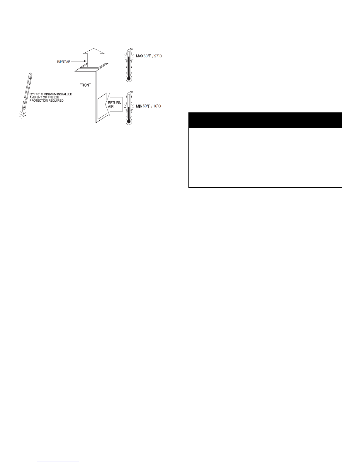
The temperature of the return air to the furnace is maintained between
60°F (16 °C) and 80°F (27 °C), with no evening setback or shutdown.
The use of the furnace while the structure is under construction is
deemed to be intermittent operation per our installation instructions.
The air temperature rise is within the rated rise range on the furnace
rating plate, and the gas input rate has been set to the nameplate value.
The filters used to clean the circulating air during the construction
process must be either changed or thoroughly cleaned prior to
occupancy.
The furnace, ductwork and filters are cleaned as necessary to remove
drywall dust and construction debris from all HVAC system components
after construction is completed.
CAUTION
Frozen and burst water pipe hazard
Failure to protect against the risk of freezing may result in property
damage. Special precautions MUST be made if installing furnace in an
area which may drop below freezing. This can cause improper operation
or damage to equipment. If furnace environment has the potential of
freezing, the drain trap and drain line must be protected
WARNING
FIRE, INJURY OR DEATH HAZARD
Failure to follow this warning could result in personal injury, death
and/or property damage.
When the furnace is installed in a residential garage, the burners and
ignitions sources must be located at leat 18” (457 mm) above the floor.
The furnace must be located or protected to avoid damage by vehicles.
When the furnace is installed in a public garage, airplane hangar, or
other building having a hazardous atmosphere, the furnace must be
installed in accordance with the NFPA 54/ANSI Z223.1-2009 or
CAN/CSA B149.2-2010 (Figure 2 Installation in a garage)
Do not install the furnace on its back or hang furnace with control
compartment facing downward. Safety control operation will be
adversely affected. Never connect return air duct to the back of the
furnace. (Figure 3 Prohibited installation)
CAUTION
Property damage hazard
Failure to follow this caution may result in burst water pipes and/or
property damage. If a condensate pump is installed, a plugged
condensate drain or a failed pump may cause the furnace to shut down.
Do not leave the home unattended during freezing weather without
turning off water supply and draining water pipes or otherwise
protecting against the risk of frozen pipes.
Ensure all condensate drain connections are secured and liquid tight.
Use the furnished tube clamps and verify tightness
the furnace rating plate.
2. Install this furnace only in a location and position as specified
in section 2.3- Location.
3. Provide adequate combustion and ventilation air to the
furnace space as specified in section 7-Venting.
4. Combustion products must be discharged outdoors. Connect
this furnace to an approved vent system only, as specified in in
section 7-Venting of these instructions.
5. Never test for gas leaks with an open flame. Use a
commercially available soap solution made specifically for the
detection of leaks to check all connections, as specified in the
“Gas Piping” section.
6. Always install furnace to operate within the furnace’s
intended temperature rise range with a duct system which has an
external static pressure within the allowable range, as specified
in section 4-Duct installation. See furnace rating label.
7. When a furnace is installed so that supply ducts carry air
circulated by the furnace to areas outside the space containing
the furnace, the return air shall also be handled by duct(s) sealed
to the furnace casing and terminating outside the space
containing the furnace. See section 4-Duct installation.
8. A gas fired furnace for installation in a residential garage
must be installed as specified in section 2.3-Location.
9. The furnace may be used for construction heat provided that
the furnace installation and operation complies with section 2.3Location.
10. The furnace is factory shipped for use with natural gas. A
CSA (A.G.A. and C.G.A.) listed accessory gas conversion kit is
required to convert furnace for use with propane gas.
11. See Table 1 Minimum clearance to combustible material
for all units for required clearances to combustible construction.
12. Maintain a 1” (25 mm) clearance from combustible materials
to supply air ductwork for a distance of 36” (914 mm) horizontally
from the furnace. See NFPA 90B or local code for further
requirements.
13. These furnaces SHALL NOT be installed directly on
carpeting, tile, or any other combustible material other than wood
flooring.
6

CAUTION
FURNACE CORROSION HAZARD
Failure to follow this caution may result in furnace damage. Air for
combustion must not be contaminated by halogen compounds, which
include fluoride, chloride, bromide, and iodine. These elements can
corrode heat exchangers and shorten furnace life. Air contaminants are
found in aerosol spray, detergents, bleaches, cleaning solvents, salts,
air fresheners, and other household products.
WARNING
CARBON MONOXIDE POISONING HAZARD
Failure to follow this warning could result in personal injury or death.
The operation of exhaust fans, kitchen ventilation fans, clothes dryers,
attic exhaust fans or fireplaces could create a NEGATIVE PRESSURE
CONDITION at the furnace. Make-up air MUST be provided for the
ventilation devices, in addition to that required by the furnace.
WARNING
CARBON MONOXIDE POISONING HAZARD
Failure to follow the steps outlined below for each appliance connected
to the venting system being placed into operation could result in carbon
monoxide poisoning or death. The following steps shall be followed for
each appliance connected to the venting system being placed into
operation, while all other appliances connected to the venting system
are not in operation:
1. Seal any unused openings in venting system;
2. Inspect the venting system for proper size and horizontal
pitch, as required in the National Fuel Gas Code, NFPA
54/ANSI Z223.1-2009 and these instructions. In Canada, refer
to CAN/CSA-B149.1-2010. Determine that there is no
blockage or restriction, leakage, corrosion and other
deficiencies, which could cause an unsafe condition
3. As far as practical, close all building doors and windows and
all doors between the space in which the appliance(s)
connected to the venting system are located and other spaces
of the building.
4. Close fireplace dampers.
5. Turn on clothes dryers and any appliance not connected to
the venting system. Turn on any exhaust fans, such as range
hoods and bathroom exhausts, so they are operating at
maximum speed. Do not operate a summer exhaust fan.
6. Follow the lighting instructions. Place the appliance being
inspected into operation. Adjust the thermostat so appliance
is operating continuously.
7. Test for spillage from draft hood equipped appliances at the
draft hood relief opening after 5 minutes of main burner
operation. Use the flame of a match or candle.
8. If improper venting is observed during any of the above tests,
the venting system must be corrected in accordance with the
National Fuel Gas Code, NFPA 54/ANSI Z223.1-2009. In
Canada, refer to CAN/ CSA-B149.1-2010.
9. After it has been determined that each appliance connected
to the venting system properly vents when tested as outlined
above, return doors, windows, exhaust fans, fireplace
dampers and any other gas-fired burning appliance to their
previous conditions of use.
WARNING
CARBON MONOXIDE POISONING HAZARD
For all venting configurations for this appliance and other gas
appliances placed into operation for the structure, provisions for
adequate combustion, ventilation, and dilution air must be provided in
accordance with:
U.S.A. Installations: Section 9.3 NFPA 54/ANSI Z223.1 1−2009, Air for
Combustion and Ventilation and applicable provisions of the local
building codes.
Canadian Installations: Part 8 of CAN/CSA−B149.1−10. Venting
Systems and Air Supply for Appliances and all authorities having
jurisdiction.
WARNING
CARBON MONOXIDE POISONING HAZARD
Failure to follow this warning could result in personal injury or death. To
route the vent pipe and combustion air pipe through the furnace, the
manufacturer supplied kit must be used. See Canadian Installations:
Part 8 of CAN/CSA−B149.1−10. Venting Systems and Air Supply for
Appliances and all authorities having jurisdiction.
Failure to properly seal the blower compartment from the furnace
vestibule could result in the circulation of carbon monoxide throughout
the structure. Seals supplied in this kit must be installed per the
instructions provided. Follow all procedures outlined in these
instructions.
2- INTRODUCTION
This 4-way multi-positioning Category IV condensing furnace is CSA
design certified as a direct vent (2 pipes) or non-direct vent (1 pipe). The
furnace is factory shipped for use with natural gas. The furnace can be
converted in the field for use with propane gas when a factory supplied
conversion kit is used. Refer to the furnace rating plate for conversion kit
information.
This Category IV furnace is approved for installation in
Manufactured/Mobile housing. The furnace must be installed in
accordance with the instruction provided in this manual. Follow all
national and local codes and standards in addition to these
instructions. The installation must comply with regulations of the serving
gas supplier, local building, heating, plumbing, and other codes.
This furnace is designed for minimum continuous return air temperature of
60 °F (16 °C) or intermittent operation down to 55 °F (13 °C) such as when
used with a night setback thermostat. Return air temperature must not
exceed 80 °F (27 °C). Failure to follow these return air temperature limits
may affect reliability of heat exchangers, motors, and controls (Figure 1
Freeze protection and return air temp.).
The furnace should be sized to provide 100 % of the design heating load
requirement plus any margin that occurs because of furnace model size
capacity increments. Heating load estimates can be made using approved
methods available from Air Conditioning Contractors of America (Manual
J); American Society of Heating, Refrigerating, and Air Conditioning
Engineers; or other approved engineering methods. Excessive over sizing
of the furnace could cause the furnace and/or vent to fail prematurely.
7
2.1- CODES AND STANDARDS
CAUTION
FURNACE RELIABILITY HAZARD
Failure to follow this caution may result in unit component damage.
Electrostatic discharge can affect electronic components. Take
precautions during furnace installation and servicing to protect the
furnace electronic control. Precautions will prevent electrostatic
discharges from personnel and hand tools which are held during the
procedure. These precautions will help to avoid exposing the control to
electrostatic discharge by putting the furnace, the control, and the
person at the same electrostatic potential.
Figure 1 Freeze protection and return air temp.
Follow all national and local codes and standards in addition to these
instructions. The installation must comply with regulations of the serving
gas supplier, local building, heating, plumbing, and other codes. In absence
of local codes, the installation must comply with the national codes listed
below and all authorities having jurisdiction. In the United States and
Canada, follow all codes and standards for the following:
2.1.1- Safety
USA: National Fuel Gas Code (NFGC) NFPA 54-2009/ANSI Z223.1-
CANADA: National Standard of Canada, Natural Gas and Propane
2.1.2- General installation
USA: NFGC and the NFPA 90B. For copies, contact the National Fire
CANADA: NSCNGPIC. For a copy, contact Standard Sales, CSA
2.1.3- Combustion and air ventilation
USA: Section 9.3 of the NFPA54/ANSI Z223.1-2009 Air for
CANADA: Part 8 of the CAN/CSA B149.1-2010, Venting Systems and Air
2.1.4- Duct systems
USA and CANADA: Air Conditioning Contractors Association
2.1.5- Acoustical lining and fibrous glass duct
USA and CANADA: current edition of SMACNA, NFPA 90B as tested by
UL Standard 181 for Class I Rigid Air Ducts.
2.1.6- Gas piping and pipe pressure testing
USA: NFPA 54/ANSI Z223.1-2009 NFGC; Chapters 5, 6, 7, and 8
CANADA: CAN/CSA-B149.1-2010, Parts 4, 5, 6, and 9.
IN THE STATE OF MASSACHUSETTS:
2009 and the Installation Standards, Warm Air Heating and Air
Conditioning Systems ANSI/NFPA 90B
Installation Code (NSCNGPIC) CAN/CSA B149.1-2010
Protection Association Inc., Battery march Park, Quincy, MA
02269; or for only the NFGC contact the American Gas
Association, 400 N. Capitol, N.W.,Washington DC 20001
International, 178 Rexdale Boulevard, Etobicoke (Toronto),
Ontario, M9W 1R3, Canada
Combustion and Ventilation
Supply for Appliances
(ACCA) (Manual D), Sheet Metal and Air Conditioning
Contractors National Association (SMACNA), or American
Society of Heating, Refrigeration, and Air Conditioning
Engineers (ASHRAE).
and national plumbing codes.
This product must be installed by a licensed plumber or gas fitter.
When flexible connectors are used, the maximum length shall not
exceed 36”. (914 mm).
When lever type gas shutoffs are used they shall be "T" handle
type.
The use of copper tubing for gas piping is not approved by the state
of Massachusetts.
2.1.7- Electrical connections
USA: National Electrical Code (NEC) ANSI/NFPA 70-2011
CANADA: CAN/CSA-B149.1-2010, Parts 4, 5, 6, and 9.
2.2- ELECTROSTATIC DISCHARGE
1) Disconnect all power to the furnace. Multiple disconnects may be
required. DO NOT TOUCH THE CONTROL OR ANY WIRE
CONNECTED TO THE CONTROL PRIOR TO DISCHARGING
YOUR BODY’S ELECTROSTATIC CHARGE TO GROUND.
2) Firmly touch the clean, unpainted, metal surface of the furnace
chassis which is close to the control. Tools held in a person’s
hand during grounding will be satisfactorily discharged.
3) After touching the chassis, you may proceed to service the
control or connecting wires as long as you do nothing to recharge
your body with static electricity (for example; DO NOT move or
shuffle your feet, do not touch ungrounded objects, etc.).
4) If you touch ungrounded objects (and recharge your body with
static electricity), firmly touch a clean, unpainted metal surface of
the furnace again before touching control or wires.
5) Use this procedure for installed and uninstalled (ungrounded)
furnaces.
6) Before removing a new control from its container, discharge your
body’s electrostatic charge to ground to protect the control from
damage. If the control is to be installed in a furnace, follow items
1 through 4 before bringing the control or yourself in contact with
the furnace. Put all used and new controls into containers before
touching ungrounded objects.
7) An ESD service kit (available from commercial sources) may
also be used to prevent ESD damage.
2.3- LOCATION
General
These furnaces are shipped with the following materials to assist in proper
furnace installation. These materials are shipped in the main blower
compartment. See Table 2 Loose parts list for loose parts bag contents.
This furnace must:
Be installed so the electrical components are protected from water;
Not be installed directly on any combustible material other than
wood flooring;
Be located close to the chimney or vent and attached to an air
distribution system. Refer to section 5 Ducts section;
8

Be provided ample space for servicing and cleaning. Always
Position
Clearance in (mm)
Rear
0
Front
0
Required for service (front)
*24'' (610)
All sides of supply plenum
*1''(25)
Sides
0
Vent
0
Top of furnace
1''
Quantity
Description
1
Plastic cap 5/8"
4
Plastic cap 1/2"
10
Screw TEKS HEX WSH #8-18 x ½
1
2" PVC pipe (Length = 1.5")
1
Drain trap
1
Drain trap gasket
2
Gasket wall pipe flange
2
Wall pipe flange
1
Clear PVC tube 5/8" ID x 24"
1
Clear PVC tube 1/2" ID x 24"
comply with minimum fire protection clearances shown in Table 1
Minimum clearance to combustible material
for all units or on the furnace rating label.
Table 1 Minimum clearance to combustible material
for all units
*See local buildings codes.
Table 2 Loose parts list
furnace should be located as close to the chimney (vertical venting) or to
the outside vent wall (horizontal venting) as possible.
When installing the furnace, provisions must be made to insure the supply
of adequate combustion and ventilation air in accordance with the air for
combustion and ventilation section of the National Fuel Gas Code, NFPA
5/ANSI Z223.1-2002, or latest edition, or applicable provisions of the local
building code.
If this furnace is to be installed down flow or in horizontal position, see
section 3-Installation of this manual.
Figure 2 Installation in a garage
The following types of furnace installations may require OUTDOOR AIR for
combustion due to chemical exposures:
Commercial buildings
Buildings with indoor pools
Laundry rooms
Hobby or craft rooms, and
Chemical storage areas
If air is exposed to the following substances, it should not be used for
combustion air and outdoor air may be required for combustion:
Permanent wave solutions
Chlorinated waxes and cleaners
Chlorine based swimming pool chemicals
Water softening chemicals
De-icing salts or chemicals
Carbon tetrachloride Halogen type refrigerants
Cleaning solvents (such as perchloroethylene)
Printing inks, paint removers, varnishes, etc.
Hydrochloric acid
Cements and glues
Antistatic fabric softeners for clothes dryers
Masonry acid washing materials
All fuel burning equipment must be supplied with air for fuel combustion.
Sufficient air must be provided to avoid negative pressure in the equipment
room or space. A positive seal must be made between the furnace cabinet
and the return air duct to prevent pulling air from the burner area.
Place the unit so that proper venting can be achieved, with a minimum
number of elbows, in accord with the instructions in this manual. The
Figure 3 Prohibited installation
2.3.1- Location relative to cooling equipment
The cooling coil must be installed parallel with, or on the downstream side
of the unit to avoid condensation in the heat exchangers. The coling coil
should be at least 6” above heat exchanger.
2.4- INTRODUCTION
2.4.1- Direct vent (2 pipes applications)
When this furnace is installed as a direct vent (2 pipes) furnace; no special
provisions for air for combustion are required. However, other gas
appliances installed in the space with the furnace may require outside air
for combustion. Follow the guidelines below to insure that other gas
appliances have sufficient air for combustion.
Direct vent installations require a dedicated combustion air and venting
system. All air for combustion is taken from outside and all combustion
products are discharged to the outdoors.
Therefore, no ventilation or combustion air openings are required.
In Canada, refer to manufacturer's instructions for supporting ULC S636
venting.
9

2.4.2- Non direct vent (1 pipe) applications
IMPORTANT: Clean and deburr all pipe cuts. The shavings must not
allowed to block the exhaust, inlet or condensate drain
pipes.
IMPORTANT: Do not common vent with any other appliance. Do not
install in the same chase or chimney with a metal or
high temperature plastic pipe from another gas or fuelburning appliance unless the required minimum
clearances to combustibles are maintained between
the approved PVC pipe and other pipes.
When the furnace is installed as a non-direct vent (1 pipe) furnace, it will
be necessary to insure there is adequate air for combustion. Other gas
appliances installed with the furnace may also require air for combustion
and ventilation in addition to the amount of combustion air and ventilation
required for the furnace.
2.4.3- Ventilated combustion air applications
When the furnace is installed using the ventilated combustion air option,
the attic or crawlspace must freely communicate with the outdoor to provide
sufficient air for combustion. The combustion air pipe cannot be terminated
in attics or crawlspaces that uses ventilation fans designed to operate
during the heating season. If ventilation fans are present in these areas,
the combustion pipe must terminate outdoor as a direct vent (2 pipes)
system.
Figure 4 Dimensional drawing
All air for combustion is piped directly to the furnace from a space that is
well ventilated with outdoor air (such as an attic, crawlspace or equipment
closet) and the space is well isolated from the living space or garage. In
addition, other gas appliances installed in the space with the furnace may
require outside air for combustion.
Provisions for adequate combustion, ventilation, and dilution air must be
provided in accordance with:
U.S.A. Installations: Section 5.3 of the NFPA 54/ANSI Z223.1-2009, Air for
Combustion and Ventilation and applicable provisions of the local building
codes.
Canada: Part 8 of the CAN/CSA-B149.1-2010, Venting Systems and Air
Supply for Appliances.
2.5- CONNECTING TO FURNACE
The exhaust air pipe connection is a 2” female PVC pipe fitting extending
through the back right side of the furnace top plate.(See Figure 5 Vent
coupling and adapter with gaskets). When 2” pipe is used, connect it
directly to this fitting. When 3” pipe is used, connect a 2” to 3” coupling to
this fitting with a short piece of 2” PVC pipe. The inlet combustion air
connection is at the front right side of the top plate.
All exhaust piping must be installed in compliance with Part 7, “Venting of
Equipment,” of the latest edition of the National Fuel Gas Code NPFA 54,
90A and 90B ANSI Z223.1-, local codes or ordinances and these
instructions:
10

Figure 5 Vent coupling and adapter with gaskets
1. Provide the space with sufficient air for proper combustion,
ventilation, and dilution of flue gases using permanent horizontal
or vertical duct(s) or opening(s) directly communicating with the
outdoors or spaces that freely communicate with the outdoors.
2. Insulate all vent runs through unconditioned spaces where below
freezing temperatures are expected with 1" thick medium
density, foil faced fiberglass or equivalent Rubatex/Armaflex
insulation.
3. For horizontal runs where water may collect, wrap the vent pipe
with self-regulating, 3 or 5 Watt heat tape. The heat tape must
be U.L./CSA. listed and installed per the manufacturer’s
instructions.
4. All piping between the furnace and the roof or outside wall
penetration is between 2” and 4”. The Table 11 and Table 13
Deduction for fitting list the maximum allowable length for the
exhaust vent pipe and intake air pipe for the number of elbows
used based on the type of termination and furnace size.
5. The minimum vent length is 5 feet.
6. All piping through the roof or outside wall is 2".
7. Terminate the vent using one of the termination options shown
in Figure 6 Vent termination
8. Elbows must be a minimum of 15” apart.
9. No fine screens may be used to cover combustion air or exhaust.
NOTE: For all installations. Extend the combustion air exhaust pipe of 18"
vertically above the furnace cabinet before turning the vent.
NOTE: Vertical piping is preferred.
Figure 6 Vent termination
2.5.1- Combustion air piping
Use a 90° elbow or two medium-radius sweep elbows to keep the inlet
downward and prevent the entry of rain. The inlet opening of the
combustion air termination must be a minimum of 12” above the
anticipated level of snow accumulation.
Install termination as follow:
1. Install a 2" coupling to the combustion air pipe at the outside wall
to prevent the termination from being pushed inward.
2. Cut a 2 1/4" length of 2" PVC pipe and connect this to the
coupling.
3. Connect another 2" coupling to the end of the 2 1/4" length of
pipe. Terminate this outer coupling 4" from the wall.
4. Attach the elbow in the final 2" coupling in the vertical position
with PVC cement.
2.5.2- Exhaust vent piping
The exhaust vent must terminate at least 12” above the combustion air
termination inlet. The maximum length of the exposed vent pipe above the
roof is 30".
All horizontal venting must be done with direct venting (2 pipes).
NOTE: The combustion air and exhaust terminations must be at least 12”
above grade or anticipated snow levels. Use alternate horizontal
terminations when termination locations are limited and higher
snow levels are anticipated.
NOTE: Ensure the location of the combustion air inlet with respect to the
exhaust vent terminal complies with
Figure 22 Direct venting.
NOTE: Slope horizontal vent piping upward a minimum of 1/4" per foot of
run so that condensate drains toward the furnace.
NOTE: Support horizontal vent piping at least every four feet. No sags or
dips are permitted.
NOTE: All furnaces with horizontal air intakes must have a drain tee
assembly and trap installed in the combustion air pipe as close to
the furnace as possible. This is to drain any water that may enter
the combustion air pipe to prevent it from entering the furnace
vestibule area.
3- INSTALLATION
The furnace is factory built for upflow position. In this position, the drain
trap can be installed on right or left side depending on air return duct.
When installing the furnace in other orientation than the upflow position,
simply re-route the tubing accordingly with the instructions provided in this
section of the manual.
11

Figure 7 Drain Trap
3.1- UPFLOW ORIENTATION
In the Upflow orientation, the condensate trap can be to the right or to the
left of the furnace. The condensate drain must be routed from the trap
through the furnace casing. Remove the knock out parts of metal and
route the hoses to the drain trap. The condensate drain can be routed
through the left (Figure 8 Left side condensate drain connection or right (
Figure 9 Right side condensate drain connection side of the casing. (The
left or right side is as you are viewing the furnace.)
Figure 8 Left side condensate drain connection
Figure 9 Right side condensate drain connection
12

3.1.1- Right side condensate drain connection
1. Remove the oblong knock-out from the right side of the casing.
2. Place the drain trap gasket on drain trap, in a way that the holes
are aligned.
3. Install the drain trap on the right side, the three outlet stub of the
drain trap toward the interior of the furnace. The three outward
stubs ends are now inside the furnace.
4. Slide the three clamps down the plain end of the drain tubes that
are already connected inside the furnace.
5. Secure the drain tubes to the trap with the clamps provided.
6. Screw in place the drain trap with two head tapping screws on
the right side of the furnace.
7. Connect the outlet drain from the drain trap to an additional
condensate piping in compliance with the local building codes;
that is a code approved drain, or to a condensate pump
approved for use with acidic furnace condensate.
3.1.2- Left side condensate drain connection
1. Remove the oblong knock-out from the side of the casing.
2. Place the drain trap gasket on drain trap.
3. Install the drain trap on the side, the two outlet stubs of the drain
trap toward the interior of the furnace. The two outward stubs
ends are now inside the furnace.
4. Slide the three clamps down the plain end of the drain tubes.
5. Secure the drain tubes to the trap with the clamps provided.
6. Screw in place the drain trap with two head tapping screws on
the side of the furnace.
7. Connect the outlet drain from the drain trap to an additional
condensate piping in compliance with the local building codes;
that is a code approved drain, or to a condensate pump approved
for use with acidic furnace condensate.
3.2- DOWN FLOW ORIENTATION
To install the furnace in down flow position, few steps are needed for
proper operation.
NOTE: It is STRONGLY RECOMMENDED to use the optional downflow base
to ensure the 2’’ clearance around the supply duct going through
the floor and the proper slope of the furnace for condensate
drainage. Also, the base allows sufficient spacing for the venting
and the drain trap.
that is a code approved drain, or to a condensate pump approved
for use with acidic furnace condensate.
Figure 10 : Down flow orientation
3.2.2- Downflow venting drainaged
All furnace with horizontal exhaust vent piping must have a drain tee
assembly and trap installed in the exhaust pipe as close to the furnace as
possible.
3.2.3- Condensate box pressure switch
The 3/16 stub just beside the drain of the condensate box must be drilled
or cut open. The PVC tubing of the pressure switch -0.2 (nearest to the ID
blower) must be connected to this stub.
Figure 11 Condensate pressure switch
3.2.1- Down flow condensate drain connection Remove all
PVC tubes from the ID blower, condensate box and vent collector and
block the stubs with furnished 5/8’’ & 1/2’’ black caps.
2. Remove the knock-out from the bottom left side of the casing.
3. Place the drain trap gasket on drain trap.
4. Install the drain trap on the bottom left side, the three outlet stubs
of the drain trap toward the interior of the furnace. The three
outward stubs ends are now inside the furnace.
5. Screw in place the drain trap with 2 head tapping screws on the
side of the furnace.
6. Install two 1/2’’ black plastic cap on the 1/2” stub of the drain trap.
See Figure 10 : Down flow orientation
7. Cut 20’’ of furnished 5/8’’ clear PVC tube and connect one end
on the port on the lower right side of the condensate box.
8. Connect the other end to 5/8’’ stub of the drain trap and secure
the tube on the gas manifold with a tie wrap.
9. Connect the outlet drain from the drain trap to an additional
condensate piping in compliance with the local building codes;
3.3- HORIZONTAL RIGHT ORIENTATION
3.3.1- Horizontal right condensate drain connection
1. Remove all PVC tubes from the ID blower, condensate box and
vent collector and block the stubs with furnished 5/8’’ & 1/2’’ black
caps.
2. Remove the knock-outs from the bottom middle side of the
casing.
3. Place the drain trap gasket on the drain trap.
13

4. Screw in place the drain trap with 2 head tapping screws on the
side of the furnace.
5. Install two 1/2” black plastic cap on the stubs of the drain trap
inside the furnace.
6. Connect a piece of 5/8’’ PVC tube to the bottom left of the
condensate box and route with an elbow to the drain trap.
7. Install the drain trap on the bottom middle side, the three outlets
stubs of the drain trap toward the interior of the furnace.
8. Connect the outlet drain from the drain trap to an additional
condensate piping in compliance with the local building codes or
to a condensate pump approved for use with acidic furnace
condensate.
NOTE : The drain trap must be vertical.
Figure 12 Horizontal right drain trap position
3.3.3- Condensate box pressure switch
The 3/16 stub just beside the drain of the condensate box must be drilled
or cut open. The PVC tubing of the pressure switch -0.2 (nearest to the ID
blower) must be connected to this stub.
The pressure switch needs now to be electrically connected in series with
the low fire pressure switch (top) with the brown jumper. See Figure 14
Pressure switch assembly and wiring diagrams.
Figure 14 Pressure switch assembly
Figure 13 Horizontal right condensate tubing
3.3.2- Horizontal right vent drainage
All furnace with horizontal exhaust vent piping must have a drain tee
assembly and trap installed in the exhaust pipe as close to the furnace as
possible (See Figure 13 Horizontal right condensate tubing).
3.4- HORIZONTAL LEFT ORIENTATION
3.4.1- Horizontal left condensate drain connection
1. Remove the knock-outs from the bottom middle side of the
casing.
2. Drill open the bottom stub of the ID blower if not already open.
Be sure to remove all debris.
3. Reroute the ID blower drain tube from the bottom of the ID blower
casing to one of the 1/2” stub. Do not screw the drain trap to
the furnace casing.
4. Block the other open ID blower drain with a 1/2’’ black cap.
5. Reroute the condensate box drain tube from the bottom of the
condensate box through the casing.
6. Reroute de vent collector drain tube to one of the 1/2” stub.
7. Apply the neoprene 7/8’’ gasket around the 5/8’’ and 1/2” tubes
at the point where they cross the furnace casing to seal the
passage.
8. Plug the 5/8’’ and 1/2” tubes to the drain trap, securing the
connections with the clamps. The drain trap must be vertical.
9. Connect the outlet drain from the drain trap to an additional
condensate piping in compliance with the local building codes; or
to a condensate pump approved for use with acidic furnace
condensate.
14

Figure 15 Horizontal left condensate drain connection
Figure 16 Return air base
4.1.1- Bottom return air inlet
In Upflow orientation, for the bottom inlet, it is possible to use a return air
base. This base allows the connection of the duct on the side with a bottom
inlet. (See
Figure 16 Return air base)
1. Cut a rectangular opening on the bottom plate of the furnace. To
know what dimension to be used, refer to the input of the furnace
as showed on Figure 4 Dimensional drawing. Install the return
air inlet as per local codes.
3.4.2- Condensate box pressure switch
The 3/16” stub just beside the drain of the condensate box must be drilled
or cut open. The PVC tubing of the pressure switch nearest to the ID
blower must be connected to this stub.
The pressure switch needs to be electrically connected in series with the
low fire pressure switch (top) with the brown jumper. See Figure 14
Pressure switch assembly and wiring diagrams.
4- DUCT INSTALLATION
4.1- RETURN AIR CONNECTIONS
The return air duct must be connected to bottom, left side or right side
NOTE: In downflow configuration, side return air is not permitted, it must
be connected to bottom.
4.1.2- Side return air inlet
1. Remove 4 knock-outs on the side of the furnace on 8 knock-outs
available. Use the knock-outs related to the furnace size as
shown on Figure 4 Dimensional drawing. This concerns the width
of the return outlet.
2. Install the return air inlet as per local codes.
4.2- FILTER ARRANGEMENT
There are no provisions for an internal filter rack in these furnaces. An
external filter is required.
4.3- SUPPLY AIR DUCTS
The supply air duct must be connected ONLY to the furnace supply outlet
air duct flanges or air conditioning coil casing (when used). DO NOT cut
main furnace casing side to attach supply air duct, humidifier, or other
accessories. All accessories MUST be connected to duct external to
furnace main casing.
NOTE: Many states, provinces and localities are considering or have
implemented standards and/or restrictions on duct sizing
practices, ductwork leakage, and/or ductwork thermal, airflow and
electrical efficiencies. CONSULT LOCAL CODE OFFICIALS for
ductwork design and performance requirement in your area.
4.4- GENERAL REQUIREMENTS
The duct system should be designed and sized according to accepted
national standards such as those published by: Air Conditioning
Contractors Association (ACCA), Sheet Metal and Air Conditioning
Contractors National Association (SMACNA) or American Society of
Heating, Refrigerating and Air Conditioning Engineers (ASHRAE) or
15

consult The Air Systems Design Guidelines reference tables available
INPUT
HIGH
45,000
60,000
75,000
105,000
120,000
LOW
31,500
42,000
52,500
73,500
84,000
OUTPUT
HIGH
42,750
57,000
71,475
99,750
115,080
LOW
29,925
39,900
50,032
69,825
80,556
EFFICIENCY
95
95
95.3
95
95.9
TEMP. RISE
40-70 °F
MAX
CFM
HIGH
Please see tables in Annex I
LOW
COOLING
DIRECT DRIVE
MOTOR TYPE
ECM
DIRECT DRIVE
MOTOR HP
1/2
3/4
3/4 1 1
BLOWER WHEEL
DIAMETER X WIDTH
11 x 6
11 x 8
11 x 9
11 x 11
11 x 11
INPUT
HIGH
45,000
60,000
75,000
105,000
120,000
LOW
31,500
42,000
52,500
73,500
84,000
OUTPUT
HIGH
42,750
56,640
71,775
99,540
115,200
LOW
29,925
39,648
50,242
69,678
80,640
EFFICIENCY
95
94.4
95.7
94.8
96
TEMP. RISE
40-70 °F
MAX
CFM
HIGH
Please see tables in Annex I
LOW
COOLING
DIRECT DRIVE
MOTOR TYPE
PSC
DIRECT DRIVE
MOTOR HP
1/2
1/2
3/4
1 1
BLOWER WHEEL
DIAMETER X WIDTH
11 x 6
11 x 8
11 x 9
11 x 11
11 x 11
from your local distributor.
The duct system should be sized to handle the required system design
CFM at the design external static pressure. The furnace airflow rates are
provided in Table 3 Air flow capacity and blower data. When a furnace is
installed so that the supply ducts carry air circulated by the furnace to
areas outside the space containing the furnace, the return air shall also be
handled by duct(s) sealed to the furnace casing and terminating outside
the space containing the furnace.
Secure ductwork with proper fasteners for type of ductwork used. Seal
supply and return duct connections to furnace with code approved tape or
duct sealer.
NOTE: Flexible connections should be used between ductwork and
furnace to prevent transmission of vibration.
Ductwork passing through unconditioned space should be
insulated to enhance system performance. When air conditioning
is used, a vapour barrier is recommended.
Table 3 Air flow capacity and blower data 2 stage variable
Maintain a 1 in. (25 mm) clearance from combustible materials to
supply air ductwork for a distance of 36 in. (914 mm) horizontally
from the furnace. See NFPA 90B or local code for further
requirements.
4.4.1- Duct work acoustical treatment
NOTE: Metal duct systems that do not have a 90 degree elbow and 10 ft.
(3 M) of main duct to the first branch take-off may require internal
acoustical lining. As an alternative, fibrous ductwork may be used
if constructed and installed in accordance with the latest edition of
SMACNA construction standard on fibrous glass ducts. Both
acoustical lining and fibrous ductwork shall comply with NFPA
90B as tested by UL Standard 181 for Class 1 Rigid air ducts.
NOTE: For horizontal applications, the top most flange may be bent past
90° to allow the evaporator coil to hang on the flange temporarily
while the remaining attachment and sealing of the coil are
performed.
Table 4 : Air flow capacity and blower data 2 stage direct drive
16

Table 5 : Air flow capacity and blower date 1 stage direct drive
INPUT
HIGH
45,000
60,000
75,000
105,000
120,000
OUTPUT
HIGH
42,750
57,000
71,475
100,065
115,440
EFFICIENCY
95
95
95.3
95.3
96.2
TEMP. RISE
40-70 °F
MAX
CFM
HIGH
Please see tables in Annex I
COOLING
DIRECT DRIVE
MOTOR TYPE
PSC
DIRECT DRIVE
MOTOR HP
1/2
1/2
3/4 1 1
BLOWER WHEEL
DIAMETER X WIDTH
11 x 6
11 x 8
11 x 9
11 x 11
11 x 11
Nominal
Iron pipe
size in.
(mm)
Internal dia.
in. (mm)
Length of pipe - FT (M)
10 (3.0)
20 (6.0)
30 (9.1)
40
(12.1)
50
(15.2)
1/2 (13)
0.622 (158)
175
120
97
82
73
3/4 (19)
0.824 (20.9)
360
250
200
170
151
1 (25)
1.049 (26.6)
680
465
375
320
285
1-1/4 (32)
1.380 (35.0)
1400
950
770
660
580
1-1/2 (39)
1.610 (40.9)
2100
1460
1180
990
900
Gas Pressure in w.c.
(psig)
Natural gas
Propane
Maximum
10.5 (0.38)
13.0 (0.47)
Minimum
4.5 (0.16)
11.0 (0.40)
5- GAS PIPING
Gas piping must be installed in accordance with national and local codes.
Refer to current edition of NFGC in the U.S.A. Refer to current edition of
CAN/CSA B149.1 in Canada. Installations must be made in accordance
with all authorities having jurisdiction. If possible, the gas supply line
should be a separate line running directly from meter to furnace.
NOTE: Use a back-up wrench on the inlet of the gas valve when
connecting the gas line to the gas valve.
NOTE: In the state of Massachusetts:
1. Gas supply connections MUST be performed by a licensed
plumber or gas fitter.
2. When flexible connectors are used, the maximum length shall
not exceed 36 in. (915 mm).
3. When lever handle type manual equipment shutoff valves are
used, they shall be "T" handle valves.
4. The use of copper tubing for gas piping is NOT approved by the
state of Massachusetts.
Report to Table 6 Maximum capacity of pipe for recommended gas pipe
sizing. Support all gas piping with appropriate straps, hangers, etc. Use a
minimum of 1 hanger every 6 ft (1.8 m). Joint compound (pipe dope)
should be applied sparingly and only to male threads of joints. Pipe dope
must be resistant to the action of propane gas.
An accessible manual equipment shut off valve MUST be installed
external to furnace casing and within 6 ft. (1.8 m) of furnace.
Install a sediment trap in riser leading to furnace as shown in Figure 17
Typical gas pipe arrangement. Connect a capped nipple into lower end of
tee. Capped nipple should extend below level of furnace gas controls.
Place a ground joint union between furnace gas control valve and exterior
manual equipment gas shutoff valve.
Figure 17 Typical gas pipe arrangement
A 1/8” (3 mm) NPT plugged tapping, accessible for test gauge connection,
MUST be installed immediately upstream of gas supply connection to
furnace and downstream of manual equipment shutoff valve.
Piping should be pressure and leak tested in accordance with the current
addition of the NFGC in the United States, local, and national plumbing
and gas codes before the furnace has been connected. Refer to current
edition of NSCNGPIC in Canada. After all connections have been made,
purge lines and check for leakage at furnace prior to operating furnace.
NOTE: The furnace gas control valve inlet pressure tap connection is
suitable to use as test gauge connection providing test pressure.
Table 7 Gas pressure
Table 6 Maximum capacity of pipe in Ft³ of gas/hr
* Cubic feet of gas per hr for gas pressures of 0.5 psig (14 in. w.c)
(Based on a 0.60 specific gravity gas)
Ref: Table 6.2 of NFPA54/ANSI Z223.1-2009
If pressure exceeds 0.38 psig (10.5 in. W.C.), gas supply pipe must be
disconnected from furnace and capped before and during supply pipe
pressure test. If test pressure is equal to or less than 0.38 psig (10.5 in.
W.C.), turn off electric shutoff switch located on furnace gas control valve
and accessible manual equipment shutoff valve before and during supply
pipe pressure test. After all connections have been made, purge lines and
check for leakage at furnace prior to operating furnace.
17

The gas supply pressure shall be within the maximum and minimum inlet
WARNING
FIRE HAZARD
Failure to follow this warning could result in personal injury, death, or
property damage.
Do not connect aluminium wire between disconnect switch and
furnace. Use only copper wire.
Max. Min.
45 000 120-60-1 127 104 10.7 12,6 14 29 (8.8) 15
60 000 120-60-1 127 104 13.1 15,6 12 36 (11.0) 20
75 000 120-60-1 127 104 13.1 15,6 12 36 (11.0) 20
105 000 120-60-1 127 104 15.8 19 12 36 (11.0) 20
120 000 120-60-1 127 104 15.8 19 12 36 (11.0) 20
Max. Min.
45 000 120-60-1 127 104 10.7 12.6 14 29 (8.8) 15
60 000 120-60-1 127 104 12.6 15 14 29 (8.8) 15
75 000 120-60-1 127 104 12.6 15 14 29 (8.8) 15
105 000 120-60-1 127 104 15.8 19 12 36 (11.0) 20
120 000 120-60-1 127 104 15.8 19 12 36 (11.0) 20
Max. Min.
45 000 120-60-1 127 104 12.8 15.3 14 36 (11.0) 20
60 000 120-60-1 127 104 12.5 14.9 12 29 (8.8) 15
75 000 120-60-1 127 104 12.5 14.9 14 29 (8.8) 15
105 000 120-60-1 127 104 15.8 19.1 12 36 (11.0) 20
120 000 120-60-1 127 104 15.8 19.1 12 36 (11.0) 20
Max. Min.
45 000 120-60-1 127 104 13.4 15.9 12 36 (11.0) 20
60 000 120-60-1 127 104 13.1 15.5 12 36 (11.0) 20
75 000 120-60-1 127 104 13.1 15.5 12 36 (11.0) 20
105 000 120-60-1 127 104 16.4 19.6 12 36 (11.0) 20
120 000 120-60-1 127 104 16.4 19.6 12 36 (11.0) 20
1 stage PSC motor
Unit Size
Volts-Hertz-
Phase
Operating Voltage
Range
Maximum
Unit Amps
Unit
Ampacity
Minimum
Wire Size
AWG
Maximum
Wire Length
Ft( m)
Maximum Fuse
or CKT BKR
Amp
2 stage PSC motor
Unit Size
Volts-Hertz-
Phase
Operating Voltage
Range
Maximum
Unit Amps
Unit
Ampacity
Minimum
Wire Size
AWG
Maximum
Wire Length
Ft( m)
Maximum Fuse
or CKT BKR
Amp
2 stage variable speed
Unit Size
Volts-Hertz-
Phase
Operating Voltage
Range
Maximum
Unit Amps
Unit
Ampacity
Minimum
Wire Size
AWG
Maximum
Wire Length
Ft( m)
Maximum Fuse
or CKT BKR
Amp
Modulating furnace
Unit Size
Volts-Hertz-
Phase
Operating Voltage
Range
Maximum
Unit Amps
Unit
Ampacity
Minimum
Wire Size
AWG
Maximum
Wire Length
Ft( m)
Maximum Fuse
or CKT BKR
Amp
supply pressures marked on the rating plate with the furnace burners and
in Table 7 Gas pressure.
5.1- GAS PIPE GROMMET
For direct vent (2 pipes) applications, the hole for the gas pipe on the
cabinet must be sealed to prevent air leakage. Install the grommet in the
hole, then insert the gas pipe and apply fillet paste.
6- ELECTRICAL CONNECTIONS
Check all factory and field electrical connections for tightness.
Supplied field wiring shall conform to the limitations of 63°F (33°C) rise.
6.1- 120 V WIRING
Furnace must have a 120 V power supply properly connected and
grounded.
NOTE: Proper polarity must be maintained for 120 V wiring. If polarity is
incorrect, control LED status indicator light will flash rapidly and
furnace will NOT operate.
Verify that the voltage, frequency, and phase correspond to that specified
on unit rating plate. Also, check to be sure that service provided by utility
is sufficient to handle load imposed by this equipment. Refer to rating plate
or
Table 8 Electrical data for equipment electrical specifications.
U.S.A. Installations:
Make all electrical connections in accordance with the current edition of
the National Electrical Code (NEC) ANSI/NFPA 70 and any local codes or
ordinances that might apply.
Canada Installations:
Make all electrical connections in accordance with the current edition of
the Canadian Electrical Code CSA C22.1 and any local codes or
ordinances that might apply.
Use a separate, fused branch electrical circuit with a properly sized fuse
or circuit breaker for this furnace. See
Table 8 Electrical data for wire size and fuse specifications. A readily
accessible means of electrical disconnect must be located within sight of
the furnace.
.
Table 8 Electrical data
18

Figure 18 Power cord installation in the furnace
INPUT
HEATING
COOLING
45,000
LOW
MED-HIGH
60,000
MED-LOW
MED-HIGH
75,000
MED-LOW
MED-HIGH
105,000
HIGH
MED-HIGH
120,000
HIGH
MED-HIGH
INPUT
HEATING 1st
STAGE
HEATING 2
nd
STAGE
COOLING
45,000
LOW
MED-LOW
MED-HIGH
60,000
LOW
MED-LOW
MED-HIGH
75,000
LOW
MED-LOW
MED-HIGH
105,000
LOW
MED-HIGH
MED-LOW
120,000
MED-LOW
HIGH
MED-HIGH
6.2- 24 V WIRING
Make field 24 V connections at the 24 V terminal strip. Connect terminal
Y/Y2 for proper cooling operation. Use only AWG No. 18, color-coded,
copper thermostat wire.
NOTE: Use AWG No. 18 color coded copper thermostat wire for lengths
up to 100ft. (30.5m). For wire lengths over 100 ft., use AWG No
16 wire.
The 24 V circuit contains an automotive type, 3-amp fuse located on the
control. Any direct shorts during installation, service, or maintenance could
cause this fuse to blow. If fuse replacement is required, use ONLY a 3
amp.
blower speeds. See airflow tables in annexe for the relation between CFM
and external static pressure applicable to your model. The cooling and
heating blower speed are shipped with the suggested fan speed describe
in table 9 and table 10. These blower speeds are set for a temperature
rise of 55°F. Blowers should be adjusted by the installer to match the
installation requirements so as to provide the correct heating temperature
rise and cooling load. To adjust the circulator blower speed, proceed as
follow:
1. Turn off the power to the furnace
2. Select the heating and cooling blower speeds that match the
installation requirements from the airflow tables in annexe.
3. Relocate the desired motor leads to the desire speed on the
motor.
4. If heating and cooling speeds are the same, a jumper wire must
be used between the heat and cool terminal on the control
board. The unused leads must be connected to the “PARK”
terminal on the control board.
5. Turn on power to the furnace.
6. Verify proper temperature rise. Excessive temperature rise can
cause limit switch tripping.
Table 9 : Suggested fan speed on 1 stage furnace
6.3- THERMOSTATS
Thermostats and Control Settings for Two Stage Furnaces.
A single stage or two stage heating and single stage or two stage cooling
thermostat may be used with the furnace. Consult the thermostat
installation instructions for specific information about configuring the
thermostat.
Thermostats and Control Settings for Single Stage furnaces.
A single stage heating and single stage or two stage cooling thermostat
may be used with the furnace. Consult the thermostat installation
instructions for specific information about configuring the thermostat.
6.4- ALTERNATE POWER SUPPLY
The furnace is designed to operate on utility generated power which has
a smooth sinusoidal waveform. If the furnace is to be operated on a
generator or other alternate power supply must produce a smooth
sinusoidal waveform for compatibility with the furnace electronics. The
alternate power supply must generate the same voltage, phase, and
frequency (Hz) as shown in
Table 8 Electrical data or the furnace rating plate.
Power from an alternate power supply that is non-sinusoidal may damage
the furnace electronics or cause erratic operation.
Contact the alternate power supply manufacturer for specifications and
details.
6.5- BLOWER SPEEDS (4 SPEED PSC MOTOR)
Furnace with model number CXX-1-D and CXX-2-D are equipped with a
multi-speed circulator blower. This blower provides ease in adjusting
Table 10 : Suggested fan speed on 2 stage furnace
19

Figure 19 Wiring diagram – One stage PSC
20

Figure 20 : Two Stage PSC - Furnace Control
21

Figure 21 : Two Stage ECM - Furnace Control
22

7- VENTING
systems must be composed of pipe, fittings, cements, and
primers listed to ULC S636.
7.1- SPECIAL VENTING REQUIREMENTS FOR
INSTALLATIONS IN CANADA
The special vent fittings and accessory concentric vent termination kits
and accessory external drain trap have been certified to ULC S636 for use
with those Royal Pipe and IPEX PVC vent components which have been
certified to this standard.
In Canada, the primer and cement must be of the same manufacturer as
the vent system GVS-65 Primer (Purple) for Royal Pipe or IPEX System
636, PVC/CPVC Primer, Purple Violet for Flue Gas Venting and GVS-65
PVC Solvent Cement for Royal Pipe or IPEX System 636(1)t, PVC
Cement for Flue Gas Venting, rated Class IIA, 65 C. must be used with
this venting system - do not mix primers and cements from one
manufacturer with a vent system from a different manufacturer.
Follow the manufacturer’s instructions in the use of primer and cement
and never use primer or cement beyond its expiration date.
The safe operation, as defined by ULC S636, of the vent system is based
on following these installation instructions, the vent system manufacturer’s
installation instructions, and proper use of primer and cement.
All fire stop and roof flashing used with this system must be UL listed
material.
Acceptability under Canadian standard CAN/CSA B149 is dependent
upon full compliance with all installation instructions. Under this standard,
it is recommended that the vent system be checked once a year by
qualified service personnel.
The authority having jurisdiction (gas inspection authority, municipal
building department, fire department, etc.) should be consulted before
installation to determine the need to obtain a permit.
*IPEX System 636™ is a trademark of IPEX Inc.
7.2- GENERAL
If this furnace replaces a furnace that was connected to a vent system or
chimney, the vent or vent connectors of other remaining appliances may
need to be re-sized. Vent systems or vent connectors of other appliance
must be sized to the minimum size as determined using appropriate table
found in the current edition of National Fuel Gas Code NFPA 54/ANSI Z-
223.1. In Canada, refer to CAN/CSA-B149.1.
An abandoned masonry chimney may be used as a raceway for properly
insulated and supported combustion-air (when applicable) and vent pipes.
Each furnace must have its own set of combustion air and vent pipes and
be terminated individually.
A furnace shall not be connected to a chimney flue serving a separate
appliance designed to burn solid fuel.
Other gas appliances with their own venting system may also use the
abandoned chimney as a raceway providing it is permitted by local code,
the current edition of the National Fuel Gas Code, and the vent or liner
manufacturer’s installation instructions. Care must be taken to prevent the
exhaust gases from one appliance from contaminating the combustion air
of other gas appliances.
7.3- MATERIALS
USA: Combustion air and vent pipe, fittings, primers, and solvents
must conform to American National Standards Institute (ANSI)
standards and American Society for Testing and Materials
(ASTM) standards. See Table 14 Approved combustion air and
vent pipe, fitting and cement materials (U.S.A. Installation for
approved materials for use in the U.S.A.)
CANADA: Special Venting Requirements for Installations in Canada must
conform to the requirements of CAN/CSA B149 code. Vent
7.4- DIRECT VENT - 2 PIPES SYSTEM
In a direct vent (2 pipes) system, all air for combustion is taken directly from
outdoor atmosphere, and all flue products are discharged to outdoor
atmosphere. Combustion air and vent pipes must terminate together in the
same atmospheric pressure zone, either through the roof (preferred) or a
sidewall. See
Figure 22 Direct venting for references to clearances required by National
code authorities.
TERMINATION REQUIREMENTS FOR THE PROVINCE OF ALBERTA
AND SASKATCHEWAN
The Provinces of Alberta and Saskatchewan require a minimum
unobstructed distance of 4 ft. (1.2 M) from the foundation to the property
line of the adjacent lot for vent termination of any appliance with an input
over 35,000 BTU/h. If there is less than 4 ft. (1.2 M) of unobstructed
distance to the property line of the adjacent lot, no type of vent termination
is permitted for appliances with inputs greater than 35,000 BTU/h. There
are no additional restrictions on unobstructed distances greater than 8 ft.
(2.4 M).
All single, two pipes and concentric vents may be used, providing all other
Code and manufacturer’s requirements in these instructions are adhered
to.
If the unobstructed distance from the foundation to the property line of the
adjacent lot is no less than 4 ft. (1.2 M) and no greater than 8 ft. (2.4 M),
it will be necessary to re-direct the flue gas plume. In this situation, a
concentric vent kit cannot be used.
A 2 pipes termination (or single pipe termination when permitted) that
redirects the flue gas away by use of an elbow or tee, certified to ULC
S636 from the adjacent property line must be used.
7.5- SIZE OF THE VENT AND COMBUSTION AIR
PIPES
Furnace combustion air and vent pipe connections are sized for 2” pipe.
Any pipe diameter change should be made outside furnace casing in
vertical pipe. Any change in diameter to the pipe must be made as close
to the furnace as reasonably possible.
The Maximum Vent Length for the vent and combustion air pipe (when used)
is determined from the Maximum Equivalent Vent Length in Table 11 or Table
12 Maximum equivalent straight vent length (single stage), minus the number
of fittings multiplied by the deduction for each type of fitting used from Table
13 Deduction for fitting. The measured length of pipe used in a single or two
pipes termination is included in the total vent length. Include a deduction for
a Tee when used for Alberta and Saskatchewan terminations.
1. Measure the individual distance from the furnace to the
termination for each pipe.
2. Select a Maximum Equivalent Vent Length (MEVL) longer than
the measured distance of the individual vent and combustion air
connections to the vent termination.
3. Count the number of elbows for each pipe.
4. For each pipe, multiply the number of elbows by the equivalent
length for the type of elbow used. Record the equivalent length
of all the elbows for each pipe.
5. If a Tee is used on the termination, record the equivalent length
of the Tee used. (see Table 13 Deduction for fitting)
6. Record the equivalent length of the termination to be used.
7. Subtract the equivalent lengths of the fittings and terminations
from the Maximum Equivalent Vent Length.
23

8. If the Maximum Vent Length calculated is longer than the
individual measured length of the vent pipe and combustion air
pipe, then the diameter of pipe selected may be used.
9. If the Maximum Vent Length calculated is shorter than the
individual measured length of either the vent pipe or the
combustion air pipe, recalculate the Maximum Vent Length using
the next larger diameter pipe.
NOTE: The vent pipe and combustion air pipe must be the same
diameter.
Figure 22 Direct venting
NOTE: If the Maximum Vent Length for diameter of the pipe selected is
longer than the measured length and the equivalent length of all
the fitting and terminations, recalculate using the next smaller
diameter. If the recalculated Maximum Vent Length is longer than
the measured length of the vent pipe and combustion air pipe,
then that diameter of pipe selected may be used.
When installing vent systems of short pipe lengths use the smallest
allowable pipe diameter.
Do not use pipe size greater than required or incomplete combustion,
flame disturbance, or flame sense lockout may occur.
24

Figure 23 Multi venting
Altitude (ft)
Unit size (Btu/hr)*
Vent pipe diameter (in.)
2"
3" and 4"
0 to 4500 ft
15,000
300
N/A
30,000
180
N/A
45,000
70
90
60,000
70
90
75,000
70
90
105,000
15
80
120,000
10
65
Altitude
(ft)
Unit size
(Btu/hr)*
Vent pipe diameter (in.)
2"
3" and 4"
0 to 4500 ft
45,000
70
90
60,000
45
90
75,000
30
90
105,000
N/A
70
120,000
N/A
40
Table 11 : Maximum equivalent straight vent length (two stage and modulating)
Table 12 Maximum equivalent straight vent length (single stage)
25
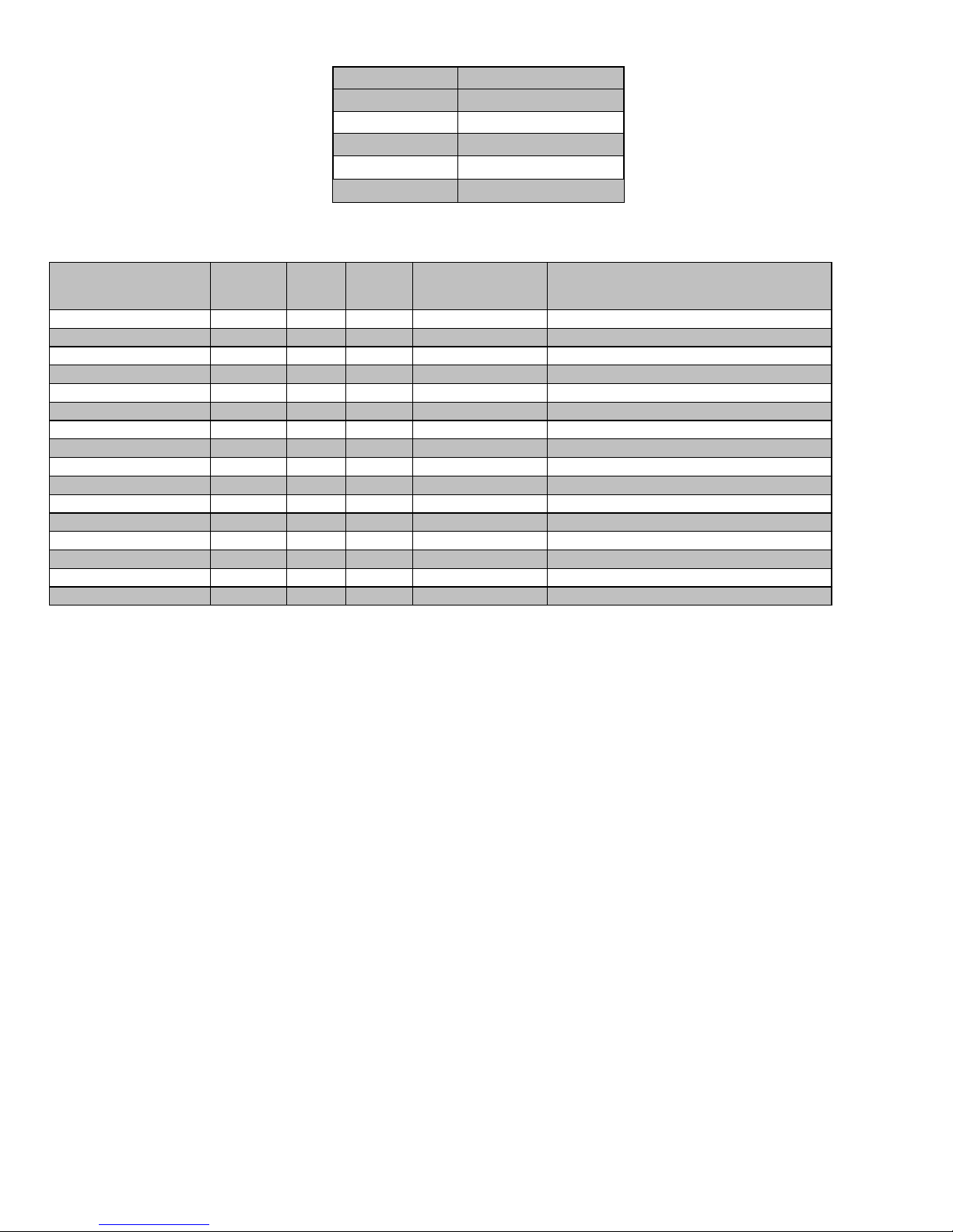
Table 13 Deduction for fitting
Type of elbow
Equivalent Length (ft.)
45° Standard
5
45° Long sweap
2½
90° Standard
10
90° Long sweap
5
Tee
1.5
ASTM SPECIFICATION
(MARKED ON MATERIAL)
MATERIAL PIPE FITTINGS
SOLVENT CEMENT
AND PRIMERS
DESCRIPTION
D1527 ABS PIPE - - Schedule-40
D1765 PVC PIPE - - Schedule-40
D2235 For ABS - - Solvent Cement For ABS
D2241 PVC PIPE - - SDR-21 & SDR-26
D2466 PVC - Fittings - Schedule-40
D2468 ABS - Fittings - Schedule-40
D2564 For ABS - - Solvent Cement For PVC
D2661 ABS PIPE Fittings - DWV at Schedule-40 IPS Sizes
D2665 PVC PIPE Fittings - DWV at Schedule-40 IPS Sizes
F438 CPVC - Fittings - Schedule-40
F441 CPVC PIPE - - Schedule-40
F442 CPVC PIPE - - SDR
F493 For CPVC - - Solvent Cement For CPVC
F628 ABS PIPE - - Cellulare Core DWV at Schedule-40 IPS sizes
F656 For PVC - - Primer For PVC
F891 PVC PIPE - - Cellulare Core Schedule-40 & DWV
Table 14 Approved combustion air and vent pipe, fitting and cement materials (U.S.A. Installation)
7.6- COMBUSTION AIR AND VENT PIPING
INSULATION GUIDELINES
The vent pipe may pass through unconditioned areas.
1. Using winter design temperature (used in load calculations), find
appropriate temperature for your application and furnace model.
2. Determine the amount of total and exposed vent pipe.
3. Determine required insulation thickness for exposed pipe
length(s).
4. When combustion air inlet piping is installed above a suspended
ceiling, the pipe MUST be insulated with moisture resistant
insulation such as Armaflex™ or other equivalent type of
insulation.
5. Insulate all vent runs through unconditioned spaces where below
freezing temperatures are expected with 1" thick medium
density, foil faced fiberglass or equivalent Rubatex/Armaflex
insulation.
6. In extremely cold climate areas, use heat trace cable as
regulated per local codes.
7. For horizontal runs where water may collect, wrap the vent pipe
with self-regulating, 3 or 5 Watt heat tape. The heat tape must
be U.L./CSA. listed and installed per the manufacturer’s
instructions.
8. Insulate combustion air inlet piping when run in warm, humid
spaces.
9. Install the insulation per the insulation manufacturer’s installation
instructions.
NOTE: Pipe length specified for maximum pipe lengths located in
unconditioned spaces cannot exceed total allowable pipe length as
calculated from Table 11 and Table 12 Maximum equivalent straight vent
length (single stage).
NOTE: The rubber coupling with drain that attaches to the vent pipe
adapter must be used. The adapter seals the vent pipe to the
casing and reduces the strain on the vent elbow attached to the
inducer.
Apply the wall pipe flange gaskets to the vent wall pipe and combustion
air wall pipe flanges.
NOTE: The vent wall pipe flange and the combustion air wall pipe flange
have the same ID.
1. Place the wall pipe flange over the 1.750” of 2” diameter pipe
provided.
2. Align the pipe on the rubber coupling with drain and tighten the
clamp around the rubber coupling.
3. Align the screw holes in the plastic wall pipe flange with the
dimples in the casing.
4. Pilot drill the screw holes for the flange in the casing and attach
the vent wall pipe flange to the furnace with sheet metal screws
5. Repeat for the air combustion wall pipe flange and secure to the
top casing.
Install the remaining vent and combustion air pipes. It is recommended
that all pipes be cut, prepared, and preassembled before permanently
cementing any joint.
1. Working from furnace to outside, cut pipe to required length(s).
2. Deburr inside and outside of pipe.
3. Chamfer outside edge of pipe for better distribution of primer and
cement.
26

4. Clean and dry all surfaces to be joined.
5. Check dry fit of pipe and mark insertion depth on pipe.
6. Insert the vent pipe into the vent elbow.
7. Insert the combustion air pipe into the adapter.
8. Pilot drill a screw hole through the adapter into the combustion
air pipe and secure the pipe to the adapter with sheet metal
screws.
9. Seal around the combustion air pipe with silicone or foil tape.
10. After pipes have been cut and preassembled, apply generous
layer of cement primer to pipe fitting socket and end of pipe to
insertion mark. Quickly apply approved cement to end of pipe
and fitting socket (over primer). Apply cement in a light, uniform
coat on inside of socket to prevent build-up of excess cement.
Apply second coat.
11. While cement is still wet, twist pipe into socket with ¼ in. turn. Be
sure pipe is fully inserted into fitting socket.
12. Wipe excess cement from joint. A continuous bead of cement will
be visible around perimeter of a properly made joint.
13. Handle pipe joints carefully until cement sets.
14. Horizontal portions of the venting system shall be supported to
prevent sagging. Support combustion air piping and vent piping
a minimum of every 5 ft. (1.5 M) [3 ft. (.91 M) for SDR-21 or -26
PVC] using perforated metal hanging strap or commercially
available hangars designed to support plastic pipe.
15. Prevent condensate from accumulating in the pipes by sloping
the combustion air piping and vent piping downward towards
furnace a minimum of ¼ in. per linear ft. with no sags between
hangers.
16. Complete the vent and combustion air pipe installation by
installing the required termination elbows. See Figure 6 Vent
termination.
17. Use appropriate methods to seal openings where combustion air
pipe and vent pipe pass through roof or sidewall.
7.7- INSTALLING THE VENT TERMINATION
A roof termination of any type will require a 4” (102 mm) flashing for a 2”
(51 mm) concentric vent or a 5” diameter (127 mm) flashing for a 3” (76
mm) concentric vent kit. For two-pipe or single pipe vent systems, a
flashing for each pipe of the required diameter will be necessary. It is
recommended that the flashing be installed by a roofer or competent
professional prior to installing the concentric vent. The terminations can
be installed on a flat or pitched roof.
7.7.1- Concentric vent
Single or multiple concentric vent must be installed as shown in Figure 23
Multi venting. Maintain the required separation distance between vents or
pairs of vents and all clearance.
Cut one 4 in. (102 mm) diameter hole for 2 in. (51 mm) kit, or one 5 in.
(127 mm) diameter hole for 3 in. (76 mm) kit in the desired location.
Loosely assemble concentric vent/combustion air termination
components together using instructions in kit. Slide assembled kit with rain
shield REMOVED through hole in wall or roof flashing.
NOTE: Do not allow insulation or other materials to accumulate inside
of pipe assembly when installing it through hole. Disassemble loose pipe
fittings. Clean and cement using same procedures as used for system
piping.
7.7.2- Two pipes termination
Two pipes vent must be installed as shown in Figure 23 Multi
ventingMaintain the required separation distance between vents or pairs
of vents and all clearance. Cut the required number of holes in the roof or
sidewall for vent and combustion air pipes. Sidewall holes for two pipes
vent terminations should be side-by-side, allowing space between the
pipes for the elbows to fit on the pipes. Holes in the roof for two pipe
terminations should be spaced no more than 18” (457 mm) apart.
Termination elbows will be installed after the vent and combustion air pipe
is installed.
When 2 or more furnaces are vented near each other, the next vent
termination must be at least 36 in. (914 mm) away from first 2 terminations.
It is important that vent terminations be made as shown in Figure 23 Multi
ventingto avoid recirculation of flue gases.
7.7.3- Sidewall termination
Determine an appropriate location for termination kit using Figure 22 Direct
venting and Figure 23 Multi venting.
1. Cut one 4” diameter hole for 2” kit, or one 5” diameter hole for 3”
kit.
2. Loosely assemble concentric vent/combustion air termination
components together using instructions in kit.
3. Slide assembled kit with rain shield REMOVED through hole
(NOTE: Do not allow insulation or other materials to accumulate
inside of pipe assembly when installing it through hole).
4. Locate assembly through sidewall with rain shield positioned no
more than 1” (25 mm) from wall.
5. Disassemble loose pipe fittings. Clean and cement using same
procedures as used for system piping.
6. Cut 2 holes, 1 for each pipe, of appropriate size for pipe size
being used.
7. Loosely install elbow in bracket and place assembly on
combustion-air pipe.
8. Disassemble loose pipe fittings. Clean and cement using same
procedures as used for system piping.
8- START UP, ADJUSTMENT AND SAFETY
CHECK
1. Furnace must have a 120 V power supply properly connected
and grounded (NOTE: Proper polarity must be maintained for
120 V wiring. Control status indicator light flashes rapidly and
furnace does not operate if polarity is incorrect.)
2. Thermostat wire connections at terminals R, W/W1, G, Y/Y2, etc.
must be made at 24 V terminal block on furnace control
3. Natural gas service pressure must not exceed 0.38 psig (10.5 in.
w.c.), but must be no less than 0.16 psig (4.5-in. w.c.). Propane
service pressure must dot exceed 0.47 psig (13 in. w.c.) but must
be no less than 0.40 psig (11 in. w.c.)
4. Blower door must be in place to complete 120 V electrical circuit
to furnace.
8.1- TO START THE FURNACE
This appliance is equipped with a hot surface ignition device. This device
lights the main burners each time the room thermostat calls for heat. See
the lighting instructions on the furnace.
During initial start-up, it is not unusual for odour or smoke to come out of
any room registers. To ensure proper ventilation, it is recommended to
open windows and doors before initial firing.
The furnace has a negative pressure switch that is a safety during a call
for heat. The induced draft blower must pull a negative pressure on the
heat exchanger to close the negative pressure switch. The induced draft
blower must maintain at least the negative pressure switch set point for
the furnace to operate. If the induced draft blower fails to close or maintain
the closing of the negative pressure switch, a “no heat call” would result.
27

1. Remove the burner compartment control access door.
WARNING
Failure to replace the burner door can cause products of combustion
to be released into the conditioned area resulting in personal injury or
death.
COOL
delay to fan-off:
Set switch
#1
45 sec.*
On
90 sec.
Off
HEAT
delay to fan-on:
Set switch
#2
30 sec.*
On
45 sec.
Off
HEAT
delay to fan-off:
Set switch
#3 #4
60 sec.
On
On
90 sec.
Off
On
120 sec.
On
Off
180 sec.*
Off
Off
2. IMPORTANT: Be sure that the manual gas control has been in
the “OFF” position for at least five minutes. Do not attempt to
manually light the main burners.
3. Set the room thermostat to its lowest setting and turn off the
furnace electrical power.
4. Turn the gas control knob to the “ON” position.
5. Replace the burner compartment control access door.
6. Turn on the manual gas stop.
7. Turn on the furnace electrical power.
8. Put thermostat to “Heat” mode and set the room thermostat at
least 10°F above room temperature to light the main burners.
9. After the burners are lit, set the room thermostat to a desired
temperature.UNIT OPERATION HAZARD
These furnaces are equipped with a manual reset limit switch in burner
assembly. This switch opens and shuts off power to the gas valve if an
overheat condition (flame rollout) occurs in burner assembly. Correct
inadequate combustion-air supply or improper venting condition before
resetting switch. DO NOT jumper this switch.
Before operating furnace, check flame rollout manual reset switch for
continuity. If necessary, press de button to reset switch. EAC-1 terminal is
energized whenever blower operates. HUM terminal is only energized
when blower is energized in heating.
8.3- SETUP SWITCHES
The furnace control has setup switches that may be set to meet the
application requirements. To set these setup switches for the appropriate
requirement:
1. Turn off electrical power.
2. Remove upper door.
3. Locate setup switches on furnace control.
4. Configure the set-up switches as necessary for the application.
5. Replace upper door and turn on electrical power.
8.4- OPTION SWITCHES – 1 STAGE, PSC
The option switches on the 50A55-843 control are used to determine the
length of the cool delay-to-fan-off, heat delay-to fan-on and heat delayto-fan-off periods. The following table shows the time periods that will
result from the various switch positions.
Table 15: Option switches positions
* Factory setting
8.4.1- Heat mode
In a typical system, a call for heat is initiated by closing the thermostat
contacts. This starts the 50A55 control’s heating sequence. The inducer
blower and optional humidifier are energized and the igniter is powered
within one second. This controller has an adaptive algorithm that adjusts
the duration of the igniter warm-up, to extend igniter life. Upon initial
application of power, the warm-up time is 17 seconds. The igniter on-time
will then be increased or decreased depending on whether or not flame is
achieved. The warm-up time is limited to a maximum of 21 seconds.
During the first 64 warm-up periods following power-up, the warm-up time
may not be less than 17 seconds.
Upon a call for heat, if the warm-up time has not been locked, it will be
decreased by one second. This reduction of the igniter on time will
continue until flame fails to be achieved (resulting in a retry).
In the event of a retry, the warm-up time will be increased by two seconds
and locked in at that duration. Once the warm-up time is locked, it remains
fixed until another call for heat results in a retry, in which case the warmup time is again increased by two seconds and remains locked.
In the event of two successive retry attempts, the warm-up time will be
unlocked and set to 21 seconds. If flame is then achieved, the warm-up
time will begin adapting again with the next call for heat. If, however, this
third attempt fails to achieve flame, the control will go into system lockout.
At the end of the igniter warm-up time, both valves in the 36E manifold
gas valve are opened. Flame must be detected within 4 seconds.
If flame is detected, the delay-to-fan-on period begins. After the delay-tofan-on period ends, the optional electronic air cleaner is energized and the
circulator fan is energized at heat speed. When the thermostat is satisfied,
the gas valve is de-energized. After proof of flame loss, the heat delay-tofan-off period begins and the inducer blower remains energized to purge
the system for 15 seconds. When the purge is complete, the inducer
blower and humidifier are de-energized. After the delay-to-fan-off period
ends, the circulator fan and electronic air cleaner are de-energized.
If flame is not detected, both valves are de-energized, the igniter is turned
off, and the 50A55 control goes into the “retry” sequence. The “retry”
sequence provides a 60 seconds wait following an unsuccessful ignition
attempt (flame not detected). After this wait, the ignition sequence is
restarted with an additional 2 seconds of igniter warm-up time. If this
ignition attempt is unsuccessful, one more retry will be made before the
control goes into system lockout.
If flame is detected, then lost, the 50A55 control will repeat the initial
ignition sequence for a total of four “recycle”. After four unsuccessful
“recycle” attempts, the control will go into system lockout.
If flame is established for more than 10 seconds after ignition, the 50A55
controller will clear the ignition attempt (or retry) counter. If flame is lost
after 10 seconds, it will restart the ignition sequence. This may occur a
maximum of five times before system lockout.
During burner operation, a momentary loss of power of 50 milliseconds or
longer will de-energize the main gas valve. When power is restored, the
gas valve will remain de-energized and a restart of the ignition sequence
will begin immediately. A momentary loss of gas supply, flame blowout, or
a shorted or open condition in the flame probe circuit will be sensed within
2.0 seconds. The gas valve will de-energize and the control will restart the
ignition sequence. Recycles will begin and the burner will operate normally
if the gas supply returns, or the fault condition is corrected, before the last
ignition attempt. Otherwise, the control will go into system lockout.
If the control has gone into system lockout, it may be possible to reset
the control by a momentary power interruption of one second or longer.
Refer to SYSTEM LOCKOUT FEATURES.
8.4.2- Cool mode
In a typical system, a call for cool is initiated by closing the thermostat
contacts. This energizes the 50A55 control and the compressor. The cool
delay-to-fan-on period begins. After the delay period ends, the optional
electronic air cleaner is energized, and the circulator fan is energized at
cool speed. After the thermostat is satisfied, the compressor is deenergized and the cool mode delay-to-fan-off period begins. After the
28

delay-to-fan off period ends, the circulator fan and electronic air cleaner
1 flash, then pause
System lockout
2 flashes, then pause
Pressure switch stuck closed
3 flashes, then pause
Pressure switch stuck open
4 flashes, then pause
Open limit switch
5 flashes, then pause
Open rollout switch
6 flashes, then pause
115 Volt AC power reversed/Improper
ground
7 flashes, then pause
Low flame sense signal
Continuous flashing
no pause)
Flame has been sensed when no
flame should be present (no call for
heat)
HEAT delay to
fan-off:
On “S1,”
set switch #:
3 4
90 sec.*
Off
Off
120 sec.
Off
On
150 sec.
On
Off
180 sec.
On
On
2nd Stage delay for single stage thermostats
Delay Time:
On "S1"
set switch #
1 2
Off*
Off
Off
10 min
On
Off
Auto min
Off
On
20 min
On
On
Average
Calculated Duty
Cycle % Equals
Or less
than
Low to High
Stage Delay
Demand
0
38
12 minutes
Light
38
50
10 minutes
Light to Average
50
62
7 minutes
Average
62
75
5 minutes
Average to Heavy
75
88
3 minutes
Heavy Light
88
100
1 minute
Heavy
(optional) are de-energized.
8.4.3- Manual fan on mode
If the thermostat fan switch is moved to the ON position, the circulator fan
(cool speed) and optional electronic air cleaner are energized. When the
fan switch is returned to the AUTO position, the circulator fan and
electronic air cleaner (optional) are de-energized.
8.4.4- Twinning interface
If the control has six screw terminals, one of which is designated TWIN,
the control is equipped with a single wire twinning interface. If twinning is
used, either control will process a call for heat, cool or fan as described
above. However, after the heat, cool, or fan-on delay time expires, both
units will energize the circulator blowers at the same time. Likewise, after
the heat, cool, or fan-off delay time expires, both units will de-energize the
circulator blowers at the same time. This allows for proper air flow to be
obtained.
To assure proper control operation, both controls must share a common
transformer ground (TR).
To enable twinning, do the following.
1. Power supplied to both furnaces must be from the same phase of
the incoming 120 VAC power.
2. Connect the TWIN screw terminals on the 50A55-843 of the
furnaces to be twinned to each other using a single wire (14-22
AWG.).
8.4.5- System lockout and diagnostic features
8.4.6- System lockout features
When system lockout occurs, the gas valve is de-energized, the circulator
blower is energized at heat speed, and, if flame is sensed, the inducer
blower is energized. The diagnostic indicator light will flash or glow
continuously to indicate system status. (System lockout will never override
the precautionary features.)
To reset the control after system lockout, do one of the following:
1. Interrupt the call for heat or cool at the thermostat for at least one
second but less than 20 seconds (if flame is sensed with the gas
valve de-energized, interrupting the call for heat at the thermostat
will not reset the control).
2. Interrupt the 24 VAC power at the control for at least one second.
You may also need to reset the flame rollout sensor switch.
3. After one hour in lockout, the control will automatically reset itself.
8.4.7- Diagnostic features
The 50A55-843 control continuously monitors its own operation and the
operation of the system. If a failure occurs, the LED will indicate a failure
code as shown below. If the failure is internal to the control, the light
will stay on continuously. In this case, the entire control should be
replaced, as the control is not field-repairable.
If the sensed failure is in the system (external to the control), the LED will
flash in the following flash-pause sequences to indicate failure status
(each flash will last approximately 0.25 seconds, and each pause will last
approximately 2 seconds).
The LED will also flash once at power-up.
8.5- OPTION SWITCHES – 2 STAGE, PSC
Option switches on the 50M51-843 control are used to determine the
length of the delay-to-fan-off periods. The following tables show the time
periods that will result from the various switch positions.
When using a single stage thermostat, second stage delay is based on
the setting of switch S1-1, S1-2 shown below.
Table 16: Option switches S1-3 & S1-4 positions
*Factory default setting
Table 17: Option switches S1-1 & S1-2 positions
*Factory default-setting – two-stage thermostat
8.5.1- Heat mode
In a typical system, a call for first stage heat is initiated by closing the W1
thermostat contacts. The inducer blower is energized at high speed and
the control waits for the low pressure switch contacts to close. The
humidifier (optional) is also energized at this time. Once the low pressure
switch contacts close, a 15 second pre-purge is initiated. Then the inducer
changes to low speed and the 120V igniter is powered. At the end of the
igniter warm-up time, the first stage of the two stage manifold gas valve is
energized (low fire).
Flame must be detected within 4 seconds. If flame is detected, the 45
seconds HEAT delay-to-fan-on period begins. After the delay-to-fan-on
period ends, the 50M51 control will energize the circulator fan at low heat
speed. The electronic air cleaner (optional) will also energize at this time.
For a two-stage thermostat, a call for second stage heat (W1 and W2)
after a call for first stage heat will energize the inducer at high speed and
the circulator at high heat speed. The second stage pressure switch
contacts will close and energize the second stage gas valve (high fire).
For a single-stage thermostat, when a call for heat occurs (W1), a 10, 20
minutes or auto mode heat staging timer will be activated (timing is
selectable with option switches S1-1 and S1-2 positions). Following this
delay, the second stage heat is energized as above.
The AUTO model algorithm is a method of energizing the second stage
gas valve based on the recent average of the heating duty cycle. During
a typical heating day, the low to high stage delay is determined by using
the average calculated duty cycle from the table below.
Once the specified delay time has expired the second stage valve will be
energized.
See the table below for the different duty cycles.
Table 18: Duty cycles
When the second stage of the thermostat is satisfied, the inducer motor is
reduced to low speed and the second stage gas valve is de-energized.
29

On the 50M51 control, the circulator will remain at high heat speed for 30
seconds following the opening of the second stage gas valve and then is
reduced to low heat speed.
When the first stage of the thermostat is satisfied, the first stage gas valve
is de-energized and the HEAT delay-to-fan-off begins timing. The inducer
will post purge for an additional 15 seconds, then the inducer and
humidifier will turn off. Upon completion of the HEAT delay-to-fan-off
period, the 50M51 circulator is turned off. The electronic air cleaner on the
control is also de-energized at this time.
If flame is not detected during the trial-for-ignition period or if the flame is
detected/sensed and then lost before completion of 10 seconds of
establishment, the gas valve is de-energized, the igniter is turned off, and
the control goes into the “retry” sequence.
The “retry” sequence provides a 60 seconds wait with the inducer inter-
purge following an unsuccessful ignition attempt (flame not detected).
After this wait, the ignition attempt is restarted. Two retries will be
attempted before the control goes into system lockout.
If flame is established for more than 10 seconds after ignition, the 50M51
controller will clear the ignition attempt (or retry) counter. If flame is lost
after 10 seconds, the control will restart the ignition sequence.
A momentary loss of gas supply, flame blowout, or a shorted or open
condition in the flame probe circuit will be sensed within 2 seconds. The
gas valve will de-energize and the control will restart the ignition
sequence. Recycles will begin and the burner will operate normally if the
gas supply returns, or the fault condition is corrected, before the last
ignition attempt. Otherwise, the control will go into system lockout.
If the control has gone into system lockout, it may be possible to reset the
control by a momentary power interruption of 10 seconds or longer. Refer
to SYSTEM LOCKOUT AND DIAGNOSTIC FEATURES.
8.5.2- Cool mode
In a typical single stage cooling system (Y connection), a call for cool is
initiated by closing the thermostat contacts. This energizes the
compressor and the electronic air cleaner (optional).
The circulator will be energized at cool speed after the COOL delay-tofan-on period. After the thermostat is satisfied, the compressor is deenergized and the COOL delay-to-fan-off period begins. After the COOL
delay-to-fan-off period ends, the circulator and the electronic air cleaner
are de-energized.
energized, interrupting the call for heat at the thermostat will not
reset the control).
2. Interrupt the 24 VAC power at the control for at least 20 seconds.
You may also need to reset the flame rollout sensor switch.
3. After one hour in lockout, the control will automatically reset itself.
8.5.7- Last fault mode
To retrieve fault codes, push and release the "LAST ERROR" button for
more than 1/5 second and less than 5 seconds. (Control will indicate this
period by solid GREEN for 1/5 to 5 seconds). The LED will flash up to five
stored fault codes, beginning with the most recent. If there are no fault
codes in memory, the LED will flash two green flashes. The control will
flash the most recent error first and the oldest error last (last in first out).
There shall be 2 seconds between codes. Solid LED error codes will not
be displayed.
8.5.8- Fault code reset
To clear the fault code memory, push and hold the "LAST ERROR" button
for more than 5 seconds and less than 10 seconds. (Control will indicate
this period by RAPID GREEN FLASH for 5 seconds to 10 seconds.) The
LED will flash three green flashes when the memory has been cleared.
8.5.9- Diagnostic features
The 50M51 control continuously monitors its own operation and the
operation of the system. If a failure occurs, the red LED on the control will
flash a failure code. If the failure is internal to the control, the light will stay
on. In this case, the entire control should be replaced, as the control is not
fielded repairable.
If the sensed failure is in the system (external to control), the LED will flash
in the following flash-pause sequences to indicate failure status (each
flash will last approximately 0.25 seconds, and each pause will last
approximately 2 seconds.)
During a second-stage error condition, the red LED when in lockout will
flash groups of double pulses. The red LED will flash on for approximately
1/15 second then off for 1/15 second then on for 1/15 second, then off for
3/10 second. The pause between groups of flashes is approximately 2
seconds. The diagnostics will indicate the specific fault through the
following codes:
8.5.3- Manual fan on mode
If the thermostat fan switch is moved to the ON position, the circulator fan
(low heat speed) and the electronic air cleaner (optional) are energized.
When the fan switch is returned to the AUTO position, the circulator and
electronic air cleaner are de-energized.
8.5.4- Twinning interface
The 50M51 is equipped with a single wire twinning interface. If twinning is
used, either control will process a call for heat, cool or fan as described
previously. However, after the heat or cool on delay time expires, both
units will energize the circulator blowers at the same time. Likewise, after
the heat or cool-off delay time expires, both units will de-energize the
circulator at the same time. This allows for the proper air flow to be
obtained.
In a twinned application, the controls are able to communicate no matter
how the transformers are phased.
To enable twinning, connect the TWIN screw terminals on the 50M51
controls of the furnaces to be twinned to each other using a single wire
(14-22 AWG).
8.5.5- System lockout and diagnostic features
8.5.6- System lockout
When system lockout occurs, the gas valve is de-energized and the low
speed inducer blower and the low heat speed circulator are energized.
The electronic air cleaner (optional) will also energize at this time. The
diagnostic indicator light will flash to indicate the system status.
To reset the control after system lockout, do one of the following:
1. Interrupt the call for heat at the thermostat for at least one second
but less than 20 seconds (if flame is sensed with the gas valve de-
30

Green
LED
Flash
Amber
LED
Flash
Red
LED
Flash
Error/Condition
Comments/Troubleshooting
1
Flame sensed when no flame
should be present
Verify the gas valve is operating and shutting down properly.
Flame in burner assemble should extinguish promptly at the
end of the cycle. Check orifices and gas pressure.
2
Pressure switch stuck closed/
inducer error
Pressure switch stuck closed. Check switch function, verify
inducer is turning off.
3
1st-stage pressure switch stuck
open/inducer error
Check pressure switch function and tubing. Verify inducer is
turning on the pulling sufficient vacuum to engage switch.
4
Open limit switch
Verify continuity through rollout switch circuit.
5
Open rollout/open fuse detect
Verify continuity through rollout switch circuit, check fuse.
6
1st-stage pressure switch cycle
lockout
If the first stage pressure switch cycles 5 times (open,
closed) during one call for heat from the thermostat the
control will lockout. Check pressure switch for fluttering,
inconsistent closure or poor vacuum pressure.
7
External lockout (retries)
Failure to sense flame is often caused by carbon deposits
on the flame sensor, a disconnected or shorted flame
sensor lead or a poorly grounded furnace. Carbon deposits
can be cleaned with emery cloth. Verify sensor is not
contacting the burner and is located in a good position to
sense flame. Check sensor lead for shorting and verify
furnace is grounded properly.
8
External lockout (ignition recycles
exceeded where flame is
established and then lost)
Check items for exceeded retries listed above and verify
valve is not dropping out allowing flame to be established
and then lost.
9
Grounding or Reversed polarity
Verify the control and furnace are properly grounded. Check
and reverse polarity (primary) if incorrect.
10
Module gas valve contacts
energized with no call for heat
Verify valve is not receiving voltage from a short. If a valve
wiring is correct and condition persists, replace module.
11
Limit switch open – possible blower
failure overheating limit
Possible blower failure, restricted air flow through appliance
or duct work. Verify continuity through limit switch circuit and
correct overheating cause.
12
Module Igniter contact failure
Fault code indicates the module igniter contacts are not
functioning properly. Replace module.
Solid
Module - internal fault condition
Module contacts for gas valve not operating or processor
fault. Reset control. If condition persists replace module.
Rapid
Twinning error Check wire
connections.
If condition persists, replace module.
3
double
2nd-stage Pressure Switch Stuck
Open/Inducer Error
Check pressure switch function and tubing. Verify inducer is
turning on and pulling sufficient vacuum to engage switch.
1
Normal Operation with call for first
stage heat
Normal operation - first stage
2
Normal Operation with call for
second stage heat
Normal operation - first stage
3
W2 present with no W1
Second stage call for heat on thermostat circuit with no call
for first stage. Verify dip switches are set for two stage
thermostat and check thermostat first stage circuit.
Configured for a multi-stage thermostat the Module will not
initiate heating unless first stage call from thermostat is
received.
4
Y present with no G call
Module will allow cooling to operate with only a "Y signal
from the thermostat but will also trigger this code. Verify
thermostat is energizing both "Y" and "G" on call for cool.
Check "G" terminal connections.
Rapid
Low
flame
sense
current
Low flame sense current is often caused by carbon deposits
on the flame sensor, a poorly grounded furnace or a
misaligned flame sense probe. Carbon deposits can be
cleaned with emery cloth. Check for improve furnace and
module ground. Verify sensor is located in or very near
flame as specified by the appliance manufacturer.
1
Standby or Call for Cool
Normal operation. Waiting for call from thermostat or
receiving thermostat call for cool.
31

8.6- OPTION SWITCH SETTINGS – 2 STAGE ECM
A B C
D
COOL
S3-1
OFF
ON
OFF
ON
S3-2
OFF
OFF
ON
ON
HEAT
S4-3
OFF
ON
OFF
ON
S4-4
OFF
OFF
ON
ON
Average
calculated
Duty Cycle
% Equals
or is less
than
Low to
High Stage
Delay
Demand
0 38 12 minutes Light
38 50 10 minutes Light to Average
50 62 7 minutes Average
62 75 5 minutes Average to Heavy
75 88 3 minutes Heavy light
88 100 1 minute Heavy
8.6.1- Thermostat type and heat-fan-off delay
8.6.5- De-humidification connection
DIP switch S5-2 (see table above) is set to “On” from the factory for
systems that do not have a dehumidification terminal connection from the
thermostat. For systems using a thermostat that provides a DeHumidification option move DIP switch S5-2 to “Off”.
Table 19: DIP Switches
8.6.2- Multi-stage thermostat set-up, factory default
DIP switches S7-1 and S7-2 (see table above) are set to the “Off” position
from the factory for use with a multi-stage thermostat. This allows the
thermostat to control staging between low and high fire.
8.6.3- Single stage thermostat set-up, module controls
staging
DIP switches, S7-1 and S7-2 (see table above) configure for a single stage
thermostat. Options include a 10 minutes delay on second stage, 20
minutes delay on second stage or an Auto setting allowing the module to
calculate the time delay for second stage based on average demand. The
“Average Calculated Duty Cycle” table shows how the module calculates
staging based on demand.
Table 20: Duty cycle
8.6.6- Normal operation – heat on
When the thermostat calls for heat the module verifies the pressure
switches are open and energizes the inducer (high speed) and optional
humidifier contacts. When the low pressure switch contacts close a 15
second pre-purge begins. After 15 seconds the inducer switches to low
speed and the 120 VAC igniter is energized. The igniter warms up for 17
seconds and the gas valve is energized on low fire. Flame must be
detected within 4 seconds. If flame is detected, a 45 seconds heat, fan on
time delay begins. This allows the heat exchanger to warm up before
energizing the circulator on low speed and (optional) Electronic Air
Cleaner contact. When the thermostat (or module) initiates second stage
the inducer is energized at high speed.
This closes the second stage inducer pressure switch then energizes the
second stage on the gas valve and then the high heat circulator speed.
8.6.7- Normal operation – heat off
When the thermostat satisfies for second stage, the control will switch high
speed inducer and high fire gas valve to low speed inducer and low fire
gas valve. After the 30 seconds high heat fan delay the circulator will drop
to low speed. When the thermostat satisfies for first stage the gas valve
de-energizes and the inducer will run low speed for a 15 seconds postpurge. The circulator runs until the heat off delay ends.
Note: If the module is configured for a single stage thermostat and
running on second stage when the call for heat ends, the
circulator will drop to low speed after 30 seconds and continue
until the heat off delay ends.
8.6.8- Cool mode
In a typical system, a call for cool is initiated by closing Y and G. This
energizes the compressor and the electronic air cleaner (optional). The
electronic air cleaner and the G and (Y or Ylo outputs to the Circulator
motor will energize after the 5 seconds cool on delay period. After the
thermostat is satisfied, the compressor is de-energized and the control
starts a 60 seconds cool circulator speed off delay. After 60 seconds the
circulator is de-energized.
8.6.4- Heat fan off delay timing
DIP switches S7-3 and S7-4 (see table above) configure the number of
seconds the blower will run after the call for heat ends. Factory default is
90 seconds.Heat pump and de-humidification
Table 21: DIP Switches
Heat pump systems
DIP switch S5-1 (see table above) is set to “On” from the factory for use
with conventional (non-Heat Pump systems). For heat pump systems
move the S5-1 DIP switch to the “Off” position. This will continuously
output an O signal to the motor whenever there is Y signal and run the
circulator blower at a constant speed when the pump is operating.
8.6.9- Adjust cooling airflow – dipswitch S3-1 and S3-2
The ECM blower can be adjusted for a range of airflow for Low Speed or
High Speed cooling.Refer to CFM tables in Annexe for the relation
between airflow, external static pressure and dipswitch setting. .
Table 22 : Dipswitch setting for airflow selection
8.6.10- Manual fan on mode
If the thermostat fan switch is moved to the “ON” position, the electronic
air cleaner (optional) and the G circulator output to the circulator motor will
be energized. When the fan switch is returned to the AUTO position, the
G circulator output and the electronic air cleaner are de-energized.
32

8.7- TROUBLESHOOTING
8.7.1- System lockout
When a system lockout occurs (1 hour), the gas valve is de-energized, the
low speed inducer blower is energized for the 60 seconds inter-purge
period and the circulator is energized for selected heat off delay if it was
previously ON. The diagnostic indicator light will flash the fault that is
present (refer to diagnostic table).
To reset the control after system lockout, do one of the following:
8.7.2- System reset
Remove 24 VAC power to the control for twenty (20) seconds
or longer to reset the control.
8.7.3- Thermostat reset
Remove the call for heat from the thermostat for a period of between (1)
second and less 20 seconds. If flame is sensed with the gas valve deenergized, interrupting the call for heat at the thermostat will not reset the
control.
8.7.4- Auto restart
After one (1) hour of internal or external lockout, the control will
automatically reset itself and go into an auto restart purge for 15 seconds.
8.7.5- Diagnostic features
The control continuously monitors its own operation and the operation of
the system. If a failure occurs the diagnostic indicator LED (DSI) will flash
a “RED” failure code. If a failure is internal to the control the “RED”
indicator will stay on continuously. In this case, the entire control should
be replaced as the control is not field-repairable. If the LED is continuously
OFF, there may be no power to the control or a failure within the control.
If the sensed failure is in the system (external to the control), the LED will
flash RED in the sequence listed in the Diagnostic Table. The LED will
also indicate “System Status” as per the Amber and Green LED signatures
listed in the Diagnostic Table. The LED will flash one RED flash at power
up.
8.7.6- Fault code retrieval
To retrieve fault codes, push and release the “LAST ERROR” button for
more than 1/5 seconds and less than 5 seconds. (Control will indicate this
period by solid GREEN for 1/5 seconds. to 5 seconds). The LED will flash
up to five stored fault codes, beginning with the most recent. If there are
no fault codes in memory, the LED will flash two green flashes. The control
will flash the most recent error first and the oldest error last (last in first
out). There shall be 2 seconds between codes. Solid LED error codes will
not be displayed.
NOTE: These error codes may be different from furnace
label or furnace manual.
8.7.7- CFM indicator
The LED (DS2) CFM flashes when the blower motor is running. The
flashing indicates the motor CFM (cubic feet per minute) air flow
designated by the furnace manufacturer. Consult the furnace
manufacturer for flash code detail.
33

Green
LED
Flash
Amber
LED
Flash
Red
LED
Flash
Error/Condition
Comments/Troubleshooting
1
Flame sensed when no flame
should be present
Verify the gas valve is operating and shutting down properly.
Flame in burner assemble should extinguish promptly at the
end of the cycle. Check orifices and gas pressure.
2
Pressure switch stuck closed/
inducer error
Pressure switch stuck closed. Check switch function, verify
inducer is turning off.
3
1st-stage pressure switch stuck
open/inducer error
Check pressure switch function and tubing. Verify inducer is
turning on the pulling sufficient vacuum to engage switch.
4
Open limit switch
Verify continuity through rollout switch circuit.
5
Open rollout/open fuse detect
Verify continuity through rollout switch circuit, check fuse.
6
1st-stage pressure switch cycle
lockout
If the first stage pressure switch cycles 5 times (open,
closed) during one call for heat from the thermostat the
control will lockout. Check pressure switch for fluttering,
inconsistent closure or poor vacuum pressure.
7
External lockout (retries)
Failure to sense flame is often caused by carbon deposits
on the flame sensor, a disconnected or shorted flame
sensor lead or a poorly grounded furnace. Carbon deposits
can be cleaned with emery cloth. Verify sensor is not
contacting the burner and is located in a good position to
sense flame. Check sensor lead for shorting and verify
furnace is grounded properly.
8
External lockout (ignition recycles
exceeded where flame is
established and then lost)
Check items for exceeded retries listed above and verify
valve is not dropping out allowing flame to be established
and then lost.
9
Grounding or Reversed polarity
Verify the control and furnace are properly grounded. Check
and reverse polarity (primary) if incorrect.
10
Module gas valve contacts
energized with no call for heat
Verify valve is not receiving voltage from a short. If a valve
wiring is correct and condition persists, replace module.
11
Limit switch open – possible blower
failure overheating limit
Possible blower failure, restricted air flow through appliance
or duct work. Verify continuity through limit switch circuit and
correct overheating cause.
12
Module Igniter contact failure
Fault code indicates the module igniter contacts are not
functioning properly. Replace module.
Solid
Module - internal fault condition
Module contacts for gas valve not operating or processor
fault. Reset control. If condition persists replace module.
Rapid
Twinning error Check wire
connections.
If condition persists, replace module.
3
double
2nd-stage Pressure Switch Stuck
Open/Inducer Error
Check pressure switch function and tubing. Verify inducer is
turning on and pulling sufficient vacuum to engage switch.
1
Normal Operation with call for first
stage heat
Normal operation - first stage
2
Normal Operation with call for
second stage heat
Normal operation - first stage
3
W2 present with no W1
Second stage call for heat on thermostat circuit with no call
for first stage. Verify dip switches are set for two stage
thermostat and check thermostat first stage circuit.
Configured for a multi-stage thermostat the Module will not
initiate heating unless first stage call from thermostat is
received.
4
Y present with no G call
Module will allow cooling to operate with only a "Y signal
from the thermostat but will also trigger this code. Verify
thermostat is energizing both "Y" and "G" on call for cool.
Check "G" terminal connections.
Rapid
Low
flame
sense
current
Low flame sense current is often caused by carbon deposits
on the flame sensor, a poorly grounded furnace or a
misaligned flame sense probe. Carbon deposits can be
cleaned with emery cloth. Check for improve furnace and
module ground. Verify sensor is located in or very near
flame as specified by the appliance manufacturer.
1
Standby or Call for Cool
Normal operation. Waiting for call from thermostat or
receiving thermostat call for cool.
34

8.8- PRIME CONDENSATE TRAP WITH WATER
Control Switch - Single Stage Valve
Control Switch - 2 Stage Valve
UNIT OPERATION HAZARD
Failure to follow this caution may result in intermittent unit operation or
performance satisfaction. Condensate trap must be PRIMED or proper
draining may not occur. The condensate trap has two internal
chambers which can ONLY be primed by pouring water into the side or
top drain inlet of condensate trap.
NOTE: Temperature rise can be determined for Minimum Heat,
Intermediate Heat and Maximum Heat operation by locking
the furnace in each mode of operation. The mode of
operation is based on the position of Set-up switch on the
furnace control board. The furnace is capable of
automatically providing proper airflow to maintain the
temperature rise within the range specified on furnace rating
plate. If temperature rise is outside this range, proceed as
follows:
a. Check gas input for minimum, intermediate and maximum heat
operation.
b. Check derate for altitude if applicable.
c. Check all return and supply ducts for excessive restrictions
causing static pressure greater than 0.5 in. w.c.
d. Check Troubleshooting Guide for Variable Speed Step
8.8.1- Check safety controls
The flame sensor, gas valve, and pressure switch were all checked in
the Start-up procedure section as part of normal operation.
1. Check Main Limit Switch
a. This control shuts off combustion system and energizes air-
circulating blower motor, if furnace overheats. By using this
method to check limit control, it can be established that limit
is functioning properly and will operate if there is a restricted
return air supply or motor failure. If limit control does not
function during this test, cause must be determined and
corrected.
b. Run furnace for at least 5 minutes.
c. Gradually block off return air with a piece of cardboard or
sheet metal until the limit trips.
d. Unblock return air to permit normal circulation.
e. Burners will re-light when furnace cools down.
f. Check Pressure Switch(es)
g. This control proves operation of the draft inducer blower.
h. Turn off 115 V power to furnace.
i. Disconnect inducer motor lead wires from wire harness.
j. Turn on 115 V power to furnace.
k. Set thermostat to “call for heat” and wait 1 minute. When
pressure switch is functioning properly, hot surface igniter
should NOT glow and control diagnostic light flashes a status
code 32. If hot surface igniter glows when inducer motor is
disconnected, shut down furnace immediately.
l. Determine reason pressure switch did not function properly
and correct condition.
m. Turn off 115 V power to furnace.
n. Reconnect inducer motor wires, replace blower door, and
turn on 115 V power.
o. Blower will run for 90 seconds before beginning the call for
heat again.
p. Furnace should ignite normally.
8.8.2- Checklist
1. Put away tools and instruments. Clean up debris.
2. Verify that blower and control doors are properly installed.
3. Cycle test furnace with room thermostat.
4. Check operation of accessories per manufacturer’s instructions.
5. Review Owner’s Manual with owner.
6. Attach literature packet to furnace.
9- OPERATING YOUR FURNACE
These furnaces are equipped with an ignition device which automatically
lights the burners. Do not try to light the burners by hand.
Before operating, smell around furnace area for gas. Be sure to smell
near floor because some gas is heavier than air and will settle to the
lowest point. See WHAT TO DO IF YOU SMELL GAS on page 44 if the
odour of gas is present. Use only your hand to turn the gas control knob;
never use tools. If the knob will not turn by hand, don’t try to repair it.
Call a qualified service technician. Force or attempted repair may
result in a fire or explosion.
9.1- START UP INSTRUCTIONS
1. STOP! Read the previous safety information.
2. Set the thermostat to the lowest setting.
3. Turn off all electric power to the furnace.
4. Remove the burner compartment access panel.
5. This appliance is equipped with an automatic ignition device.
Do not try to light the burners by hand.
6. Move the gas control switch to “OFF” (see Figure 24).
Figure 24 Control Switch – Modulating Valve
7. Wait 5 minutes to clear out any gas, then smell for gas (including
at the bottom of the unit near the ground). If you smell gas, stop
and follow the directions in WHAT TO DO IF YOU SMELL GAS
on page 44. If you don’t smell gas, continue to next step.
8. Move the gas control knob or switch to “ON”.
9. Replace the burner compartment access panel.
10. Turn on all electric power to the furnace.
11. Set the thermostat to the desired setting.
12. If the furnace will not operate, follow the instructions found below
in to turn off Gas to Furnace and call your service technician or
gas supplier.
9.2- SHUTTING DOWN THE FURNACE
To shut down the furnace, set the thermostat to the “OFF” position.
9.2.1- To turn off gas to furnace
1. Set the thermostat to the lowest setting.
2. Turn off all electric power to the furnace if service is to be
performed.
3. Remove the burner compartment access panel.
4. Move the gas control knob or switch to “OFF” (see Figure 24). Do
not force.
5. Replace the burner compartment access panel.
35
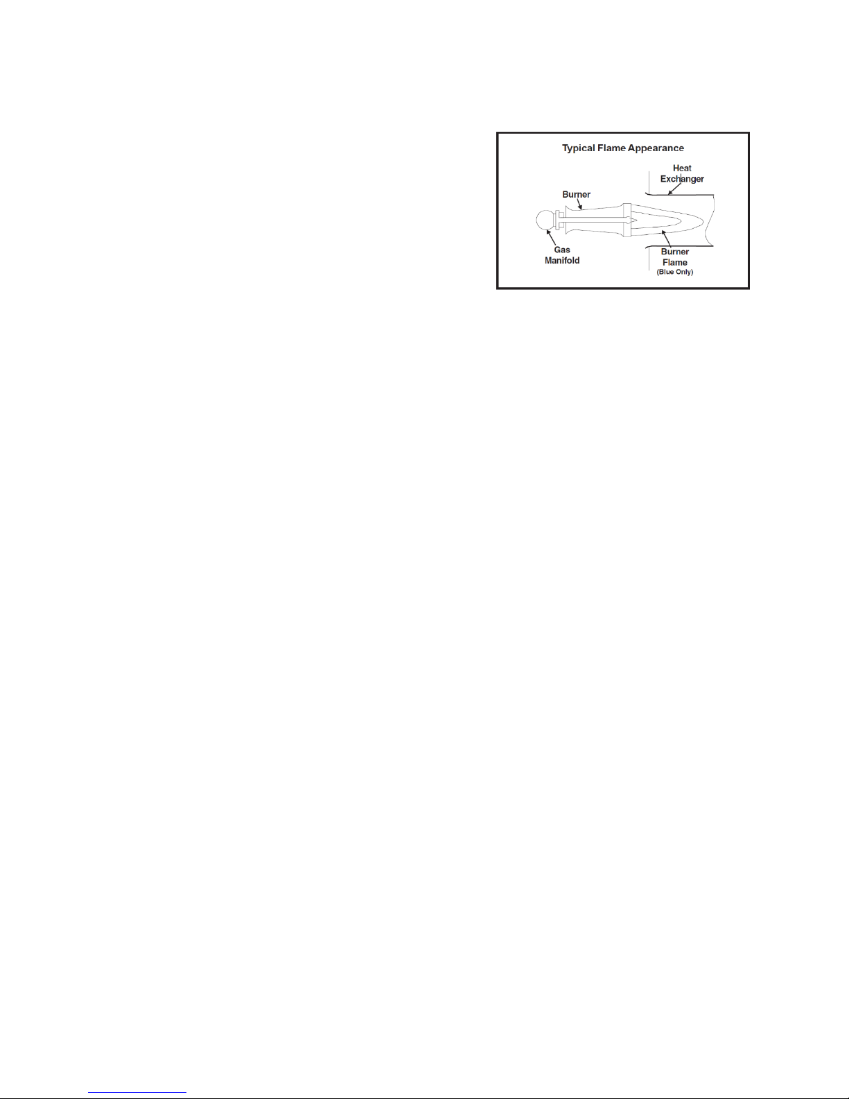
10- MAINTENANCE OF YOUR FURNACE
There are routine maintenance steps you should take to keep your
furnace operating efficiently. This maintenance will assure longer life,
lower operating costs, and fewer service calls.
In addition to the maintenance procedures listed in this manual, there
are also other service and maintenance procedures that require the
skills of a service person that has specialized tools and training.
Personal injury can result if you are not qualified to do this work.
Please call your dealer when service is needed.
Your gas furnace is designed to give many years of efficient, satisfactory
service. However, the varied air pollutants commonly found in most
areas can affect longevity and safety. Chemicals contained in everyday
household items such as laundry detergents, cleaning sprays, hair
sprays, deodorizers, and other products which produce airborne
residuals may have an adverse effect upon the metals used to construct
your appliance. The cabinet of the furnace can be cleaned with soap and
water. Grease spots can be removed with a household cleaning agent.
It is important that you conduct periodic physical inspections of your
appliance, paying special attention to the gas burner and the flue outlet
from the furnace. These components are located at the front of the unit.
A flashlight will be useful for these inspections. Make one inspection
prior to the beginning of the heating season and another during the
middle.
Should you observe unusual amounts of any of the following conditions,
it is important that you call your authorized dealer at once to obtain a
qualified service inspection:
Rust, flakes, or other deposits
Coatings
Corrosion
Even if no unusual rust or other conditions are observed, it is
recommended that the furnace be inspected and serviced at least
once per year by a qualified service technician. Regular inspections
and planned maintenance will assure many years of economic
performance from your gas furnace.
10.1- CLEANING/REPLACING THE FILTER
It is very important to clean or replace the air filter regularly.
Dirty filters are the most common cause of inadequate heating or cooling
performance and can sharply increase the operational costs of your unit.
In some cases, they can double the cost. The air filter should be
inspected at least every 6 weeks and cleaned or replaced as
required.
Your furnace may use either a disposable filter or a cleanable filter. The
type of filter may be indicated on a label attached to the filter. If a
disposable filter is used, replace with the same type and size. To remove
excess dirt from a cleanable filter, shake filter and/or use a vacuum
cleaner. Wash filter in soap or detergent water and replace after filter is
dry.
Cleanable filters do not need to be oiled after washing. Cleanable filters
may be replaced with disposable filters.
If your air distribution system has a central return air filter-grille, the
furnace does not need a filter. Filter grilles can be maintained the same
way as cleanable filters (see above).
10.1.1- Filter location
The filter on your furnace will be located in one of two different locations:
- On one side of the furnace
- On the bottom of the furnace
is present. If your observations indicate improper flame adjustment, call
your authorized service dealer for service. Do not attempt to adjust
flame!
Your service representative will perform this adjustment correctly.
Figure 25 Typical Flame Appearance
10.4- CONDENSATE COLLECTION AND DISPOSAL
SYSTEM (IF APPLICABLE)
If the furnace has a condensate drain, it is incorporated within the
furnace and is self-priming. The condensate system must not be
exposed to temperatures under 32°F.
Make sure the condensate drain line does not become blocked or
plugged. Visual inspection of condensate flow can easily be made while
the furnace is operating. Use a flashlight to illuminate discharge end of
the condensate drain that is placed in the sewer opening. The furnace
will not operate properly if condensate drain line becomes blocked or
plugged. If this event occurs, have the furnace inspected by a qualified
service technician.
10.5- ROLLOUT SWITCH
This unit is equipped with a manual reset high temperature sensor or
rollout switch. In the unlikely event of a sustained burner flame rollout,
the rollout switch will shut off the flow of gas by closing the gas valve.
The switch is located inside the gas burner area. Flame rollout can be
caused by blockage of the power vent system, a blocked heat
exchanger, or improper gas pressure or adjustment. If this event occurs,
the unit will not operate properly. The gas supply to the unit should be
shut off and no attempt should be made to place it in operation. The
system should be inspected by a qualified service technician.
10.6- SAFETY INTERLOCK SWITCH
The blower compartment door on your high efficiency gas furnace is
equipped with a safety interlock switch that will automatically shut off
your complete system (including blower) once the door is removed. This
is for your personal safety. Be sure to check your furnace for proper
operation once the door or panel has been replaced. If the system does
not operate once the panel has been replaced, try removing and
replacing it once again. If the furnace still does not operate, call your
dealer for service.
10.7- REPAIR PARTS
The repair parts are available from your local distributor. When ordering
parts: include the complete furnace model number and serial number
which are printed on the rating plate located on the furnace. For part
numbers refer to
10.2- LUBRICATION
Lubrication of the bearings in the circulating air blower motor and the
combustion blower motor is not recommended.
10.3- BURNER FLAME
While the furnace is in operation, observe the burner flames. Compare
these observations to Figure 25 to determine if proper flame adjustment
36

Figure 26 Exploded view 1 stage PSC
37

38

Table 23 Part list - 1 stage PSC
#
Description
C45-1-D
C60-1-D
C75-1-D
C105-1-D
C120-1-D
1
Heat exchanger assembly
B40508-03
B40508-04
B40508-05
B40508-07
B40508-08
2
Back panel assembly
B40511-01
B40511-02
B40511-03
B40511-03
B40511-03
3
Right panel assembly
B40510-33
B40510-33
B40510-33
B40510-33
B40510-33
4
Loose part bag
B40569-01
B40569-02
B40569-02
B40569-02
B40569-02
5
Hose 5/8
B30157-34
B30157-34
B30157-34
B30157-34
B30157-34
6
Hose 1/2
B30157-38
B30157-38
B30157-38
B30157-38
B30157-38
7
Hose 3/16
B30157-40
B30157-40
B30157-40
B30157-40
B30157-40
8
Floor
B40546-01
B40546-02
B40546-02
B40546-03
B40546-03
9
Blower assembly
B40518-01
B40518-02
B40518-03
B40518-04
B40518-04
10
Electric blower kit
B40590-01
B40590-01
B40590-01
B40590-02
B40590-02
11
Separator assembly
B40513-07
B40513-08
B40513-09
B40513-11
B40513-12
12
Inducer restrictor
B40563-07
B40563-04
B40698
N/A
N/A
13
Pressure switch assembly
B40675-03
B40675-04
B40675-05
B40675-07
B40675-08
14
Gas valve
R01H012
R01H012
R01H012
R01H012
R01H012
15
Control card assembly
B40697
B40697
B40697
B40697
B40697
16
Lower door assembly
B40570-01
B40570-02
B40570-02
B40570-03
B40570-03
17
Upper door assembly
B40571-01
B40571-02
B40571-02
B40571-03
B40571-03
18
Left panel assembly
B40509-01
B40509-01
B40509-01
B40509-01
B40509-01
19
Elect. Kit inverter/blower
B40589-01
B40589-01
B40589-01
B40589-02
B40589-02
20
Elect. Kit principal harness
B40591-01
B40591-01
B40591-01
B40591-02
B40591-02
21
Complete gas manifold assembly
B40514-03
B40514-04
B40514-05
B40514-07
B40514-08
22
ID blower assembly
B40578-04
B40578-01
B40578-01
B40578-01
B40578-01
23
Top panel assembly
B40512-01
B40512-02
B40512-02
B40512-03
B40512-03
24
Blower rail
B40552
B40552
B40552
B40552
B40552
25
Door switch
L07H001
L07H001
L07H001
L07H001
L07H001
26
Observation port w Dettson logo
B40565
B40565
B40565
B40565
B40565
27
Observation port
L04Z022
L04Z022
L04Z022
L04Z022
L04Z022
28
Grommet
G14F017
G14F017
G14F017
G14F017
G14F017
29
Pressure switch support
B40560
B40560
B40560
B40560
B40560
30
Pressure switch (condensate box)
R99F035
R99F035
R99F035
R99F035
R99F035
31
Pressure switch
R99F043
R99F042
R99F048
R99F039
R99F039
32
Drain trap gasket
B40568
B40568
B40568
B40568
B40568
33
PVC pipe
B40571-02
B40571-01
B40571-01
B40571-01
B40571-01
34
Drain trap
B40535
B40535
B40535
B40535
B40535
35
Venting flange gasket
B40567
B40567
B40567
B40567
B40567
36
Venting flange
B40533
B40533
B40533
B40533
B40533
37
Igniter
R03K005
R03K005
R03K005
R03K005
R03K005
38
Roll out switch
R02N022
R02N022
R02N022
R02N022
R02N022
39
Gas manifold assembly
B40527
B40528
B40529
B40531
B40532
40
Orifice #48 natural gas
R04I001
R04I001
R04I001
R04I001
R04I001
41
Flame detector
R03J004
R03J004
R03J004
R03J004
R03J004
42
Clamp 5/8
G99Z035
G99Z035
G99Z035
G99Z035
G99Z035
43
Elbow 5/8
G07J007
G07J007
G07J007
G07J007
G07J007
44
Condensate box
B40526-01
B40526-02
B40526-02
B40526-03
B40526-04
45
High limit
R02N026
R02N024
R02N023
R02N024
R02N024
46
Baffle
B40572
B40572
B40572
B40572
B40572
47
Smoke box
B40539-01
B40539-02
B40539-02
B40539-03
B40539-04
48
Rubber collar for venting
B40580
B40580
B40580
B40580
B40580
49
ID blower
Z01K007
Z01K007
Z01K007
Z01K007
Z01K007
50
Elbow 1/2
G07J006
G07J006
G07J006
G07J006
G07J006
51
Clamp 1/2
G99Z034
G99Z034
G99Z034
G99Z034
G99Z034
52
Capacitor
L01I002
L01I002
L01I005
L01I003
L01I003
53
Motor assembly PSC
B03684-02
B03684-02
B01891-07
B01891-08
B01891-08
54
Motor PSC
L06H004
L06H004
L06I004
L06K004
L06K004
55
Motor mounting bracket
B01889
B01889
B01889
B01889
B01889
56
Blower
Z01I033
Z01I035
Z01I036
Z01I038
Z01I038
57
Oval cap for capitor
L99Z007
L99Z007
L99Z007
L99Z007
L99Z007
58
Bracket for capacitor
B01024
B01024
B01024
B01024
B01024
59
Control board 24V
R99G013
R99G013
R99G013
R99G013
R99G013
60
Control board support
B40559
B40559
B40559
B40559
B40559
61
Transformer 120V-24V
L01F009
L01F009
L01F009
L01F009
L01F009
62
ID blower and PVC elbow ass
N/A
B40766-01
B40766-01
B40766-01
B40766-01
Options
C45-1-D
C60-1-D
C75-1-D
C105-1-D
C120-1-D
Bottom return base assembly
B40691-01
B40691-02
B40691-02
B40691-03
B40691-03
Downflow base
B40632-01
B40632-02
B40632-02
B40632-03
B40632-03
Transition A coil
B40693-01
---
---
---
---
Conversion kit propane
B40574-07
B40574-10
B40574-13
B40574-19
B40574-21
Orifice #56 (LP)
R01I002
R01I002
R01I002
R01I002
R01I002
Replacement kit for drain trap
K01021
K01021
K01021
K01021
K01021
39
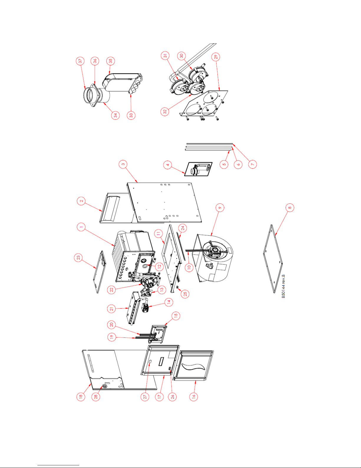
Figure 27 Exploded view 2 stage PSC
40

41

#
Description
C45-2-D
C60-2-D
C75-2-D
C105-2-D
C120-2-D
1
Heat exchanger assembly
B40508-03
B40508-04
B40508-05
B40508-07
B40508-08
2
Back panel assembly
B40511-04
B40511-05
B40511-05
B40511-06
B40511-06
3
Right panel assembly
B40510-34
B40510-34
B40510-34
B40510-34
B40510-34
4
Loose part bag
B40569-01
B40569-02
B40569-02
B40569-02
B40569-02
5
Hose 5/8
B30157-34
B30157-34
B30157-34
B30157-34
B30157-34
6
Hose 1/2
B30157-38
B30157-38
B30157-38
B30157-38
B30157-38
7
Hose 3/16
B30157-40
B30157-40
B30157-40
B30157-40
B30157-40
8
Floor
B40546-01
B40546-02
B40546-02
B40546-03
B40546-03
9
Blower assembly
B40518-01
B40518-02
B40518-03
B40518-04
B40518-04
10
Electric blower kit
B40594-01
B40594-01
B40594-01
B40594-02
B40594-02
11
Separator assembly
B40513-01
B40513-02
B40513-03
B40513-05
B40513-06
12
Inducer restrictor
B40563-07
B40563-04
B40698
N/A
N/A
13
Pressure switch assembly
B40675-11
B40675-12
B40675-13
B40675-15
B40675-16
14
Gas valve
R01I003
R01I003
R01I003
R01I003
R01I003
15
Control card assembly
B40696
B40696
B40696
B40696
B40696
16
Lower door assembly
B40570-04
B40570-05
B40570-05
B40570-06
B40570-06
17
Upper door assembly
B40571-01
B40571-02
B40571-02
B40571-03
B40571-03
18
Left panel assembly
B40509-02
B40509-02
B40509-02
B40509-02
B40509-02
19
Elect. Kit inverter/blower
B40592-01
B40592-01
B40592-01
B40592-02
B40592-02
20
Elect. Kit principal harness
B40593-01
B40593-01
B40593-01
B40593-02
B40593-02
21
Complete gas manifold assembly
B40514-03
B40514-04
B40514-05
B40514-07
B40514-08
22
ID blower assembly
B40578-05
B40578-02
B40578-02
B40578-02
B40578-02
23
Top panel assembly
B40512-01
B40512-02
B40512-02
B40512-03
B40512-03
24
Blower rail
B40552
B40552
B40552
B40552
B40552
25
Door switch
L07H001
L07H001
L07H001
L07H001
L07H001
26
Observation port w Dettson logo
B40565
B40565
B40565
B40565
B40565
27
Observation port
L04Z022
L04Z022
L04Z022
L04Z022
L04Z022
28
Grommet
G14F017
G14F017
G14F017
G14F017
G14F017
29
Pressure switch support
B40560
B40560
B40560
B40560
B40560
30
Pressure switch (condensate box)
R99F035
R99F035
R99F035
R99F035
R99F035
31
Pressure switch (high fire)
R99F043
R99F042
R99F048
R99F039
R99F041
32
Pressure switch (low fire)
R99F039
R99F050
R99F050
R99F050
R99F050
33
Garniture purgeur
B40568
B40568
B40568
B40568
B40568
34
PVC pipe
B40571-02
B40571-01
B40571-01
B40571-01
B40571-01
35
Drain trap
B40535
B40535
B40535
B40535
B40535
36
Venting flange gasket
B40567
B40567
B40567
B40567
B40567
37
Venting flange
B40533
B40533
B40533
B40533
B40533
38
Igniter
R03K005
R03K005
R03K005
R03K005
R03K005
39
Roll out switch
R02N022
R02N022
R02N022
R02N022
R02N022
40
Gas manifold assembly
B40527
B40528
B40529
B40531
B40532
41
Orifice #48 natural gas
R04I001
R04I001
R04I001
R04I001
R04I001
42
Flame detector
R03J004
R03J004
R03J004
R03J004
R03J004
43
Clamp 5/8
G99Z035
G99Z035
G99Z035
G99Z035
G99Z035
44
Elbow 5/8
G07J007
G07J007
G07J007
G07J007
G07J007
45
Condensate box
B40526-01
B40526-02
B40526-02
B40526-03
B40526-04
46
High limit
R02N026
R02N024
R02N023
R02N024
R02N024
47
Baffle
B40572
B40572
B40572
B40572
B40572
48
Smoke box
B40539-01
B40539-02
B40539-02
B40539-03
B40539-04
49
Rubber collar for venting
B40580
B40580
B40580
B40580
B40580
50
ID blower
Z01K006
Z01K006
Z01K006
Z01K006
Z01K006
51
Elbow 1/2
G07J006
G07J006
G07J006
G07J006
G07J006
52
Clamp 1/2
G99Z034
G99Z034
G99Z034
G99Z034
G99Z034
53
Capacitor
L01I002
L01I002
L01I005
L01I003
L01I003
54
Motor assembly PSC
B03684-02
B03684-02
B01891-07
B01891-08
B01891-08
55
Motor PSC
L06H004
L06H004
L06I004
L06K004
L06K004
56
Motor mounting bracket
B01889
B01889
B01889
B01889
B01889
57
Blower
Z01I033
Z01I035
Z01I036
Z01I038
Z01I038
58
Oval cap for capitor
L99Z007
L99Z007
L99Z007
L99Z007
L99Z007
59
Bracket for capacitor
B01024
B01024
B01024
B01024
B01024
60
Control board 24V
R99G015
R99G015
R99G015
R99G015
R99G015
61
Control board support
B40559
B40559
B40559
B40559
B40559
62
Transformer 120V-24V
L01F009
L01F009
L01F009
L01F009
L01F009
63
ID blower and PVC elbow ass
N/A
B40766-02
B40766-02
B40766-02
B40766-02
Options
C45-2-D
C60-2-D
C75-2-D
C105-2-D
C120-2-D
Bottom return base assembly
B40691-01
B40691-02
B40691-02
B40691-03
B40691-03
Downflow base
B40632-01
B40632-02
B40632-02
B40632-03
B40632-03
Transition A coil
B40693-01
---
---
---
---
Conversion kit propane
B40574-08
B40574-11
B40574-14
B40574-20
B40574-23
Orifice #56 (LP)
R01I002
R01I002
R01I002
R01I002
R01I002
Replacement kit for drain trap
K01021
K01021
K01021
K01021
K01021
Table 24: Part list – 2 Stage, PSC
42

Figure 28 Exploded view 2 stage ECM
43
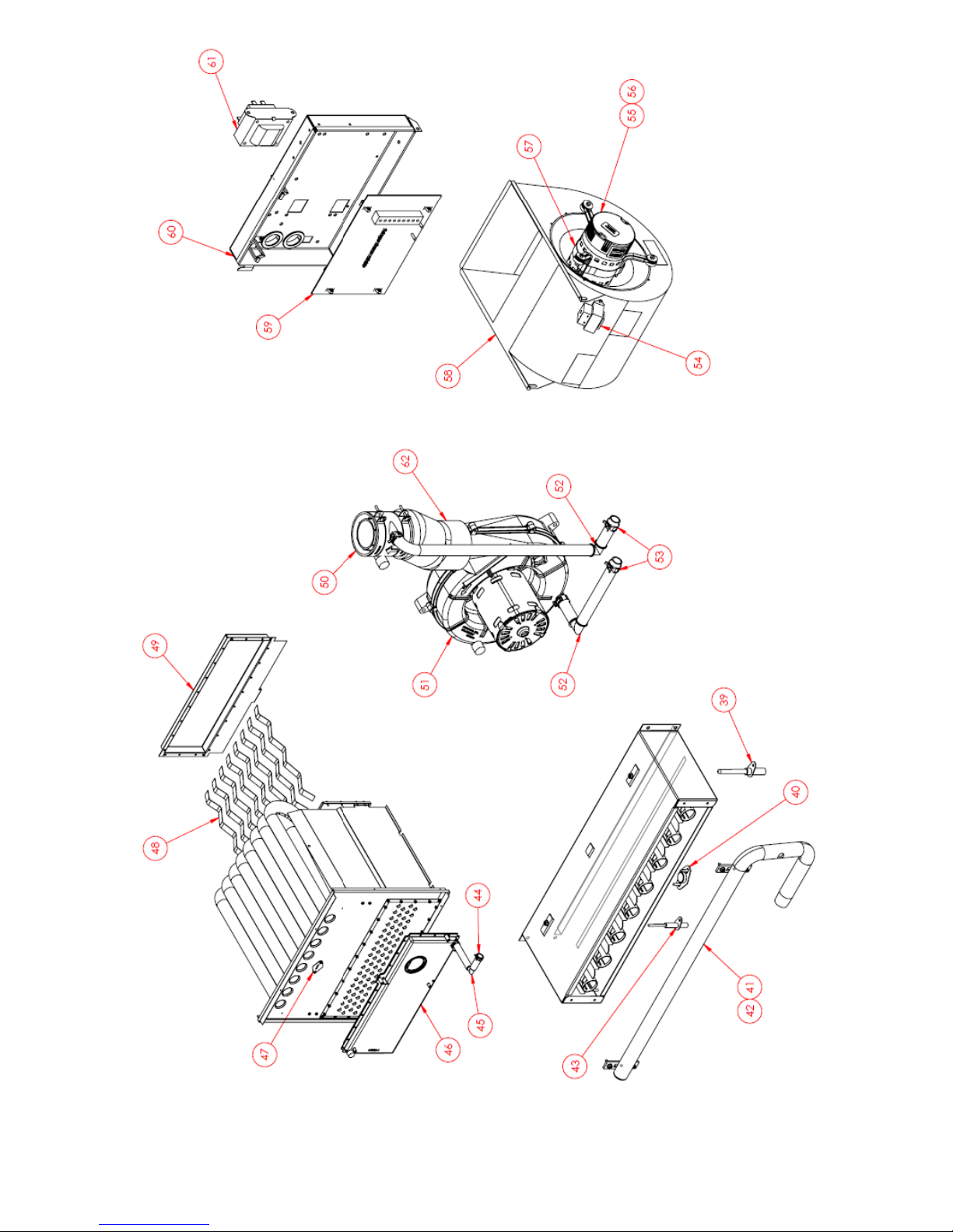
44

Table 25: Part list – 2 Stage, ECM
#
Description
C45-2-V
C60-2-V
C75-2-V
C105-2-V
C120-2-V
1
Heat exchanger assembly
B40508-03
B40508-04
B40508-05
B40508-07
B40508-08
2
Back panel assembly
B40511-04
B40511-05
B40511-05
B40511-06
B40511-06
3
Right panel assembly
B40510-34
B40510-34
B40510-34
B40510-34
B40510-34
4
Loose part bag
B40569-01
B40569-02
B40569-02
B40569-02
B40569-02
5
Hose 5/8
B30157-34
B30157-34
B30157-34
B30157-34
B30157-34
6
Hose 1/2
B30157-38
B30157-38
B30157-38
B30157-38
B30157-38
7
Hose 3/16
B30157-40
B30157-40
B30157-40
B30157-40
B30157-40
8
Floor
B40546-01
B40546-02
B40546-02
B40546-03
B40546-03
9
Blower assembly
B40604-03
B40604-04
B40604-05
B40604-07
B40604-08
10
Electric blower kit
B40581-01
B40581-01
B40581-01
B40581-02
B40581-02
11
Electric blower kit
B03242-04
B03242-04
B03242-04
B03242-05
B03242-05
12
Separator assembly
B40513-01
B40513-02
B40513-03
B40513-05
B40513-06
13
Inducer restrictor
B40563-07
B40563-04
B40698
N/A
N/A
14
Pressure switch assembly
B40675-19
B40675-20
B40675-21
B40675-23
B40675-24
15
Gas valve
R01I003
R01I003
R01I003
R01I003
R01I003
16
Control card assembly
B40695
B40695
B40695
B40695
B40695
17
Lower door assembly
B40570-07
B40570-08
B40570-08
B40570-09
B40570-09
18
Upper door assembly
B40571-01
B40571-02
B40571-02
B40571-03
B40571-03
19
Left pannel assembly
B40509-02
B40509-02
B40509-02
B40509-02
B40509-02
20
Elect. Kit inverter blower
B40592-01
B40592-01
B40592-01
B40592-02
B40592-02
21
Elect. Kit principal harness
B40593-01
B40593-01
B40593-01
B40593-02
B40593-02
22
Complete gas manifold assembly
B40514-03
B40514-04
B40514-05
B40514-07
B40514-08
23
ID blower assembly
B40578-05
B40578-02
B40578-02
B40578-02
B40578-02
24
Top panel assembly
B40512-01
B40512-02
B40512-02
B40512-03
B40512-03
25
Blower rail
B40552
B40552
B40552
B40552
B40552
26
Door switch
L07H001
L07H001
L07H001
L07H001
L07H001
27
Observation port w Dettson logo
B40565
B40565
B40565
B40565
B40565
28
Observation port
L04Z022
L04Z022
L04Z022
L04Z022
L04Z022
29
Grommet
G14F017
G14F017
G14F017
G14F017
G14F017
30
Pressure switch support
B40560
B40560
B40560
B40560
B40560
31
Pressure switch (condensate box)
R99F035
R99F035
R99F035
R99F035
R99F035
32
Pressure switch (high fire)
R99F043
R99F042
R99F048
R99F039
R99F041
33
Pressure switch (low fire)
R99F039
R99F050
R99F050
R99F050
R99F050
34
Drain trap gasket
B40568
B40568
B40568
B40568
B40568
35
PVC pipe
B40571-02
B40571-01
B40571-01
B40571-01
B40571-01
36
Drain trap
B40535
B40535
B40535
B40535
B40535
37
Venting flange gasket
B40567
B40567
B40567
B40567
B40567
38
Venting flange
B40533
B40533
B40533
B40533
B40533
39
Igniter
R03K005
R03K005
R03K005
R03K005
R03K005
40
Roll out switch
R02N022
R02N022
R02N022
R02N022
R02N022
41
Gas manifold assembly
B40527
B40528
B40529
B40531
B40532
42
Orifice #48 natural gas
R04I001
R04I001
R04I001
R04I001
R04I001
43
Flame detector
R03J004
R03J004
R03J004
R03J004
R03J004
44
Clamp 5/8
G99Z035
G99Z035
G99Z035
G99Z035
G99Z035
45
Elbow 5/8
G07J007
G07J007
G07J007
G07J007
G07J007
46
Condensate box
B40526-01
B40526-02
B40526-02
B40526-03
B40526-04
47
High limit
R02N026
R02N024
R02N023
R02N024
R02N024
48
Baffle
B40572
B40572
B40572
B40572
B40572
49
Smoke box
B40539-01
B40539-02
B40539-02
B40539-03
B40539-04
50
Rubber collar for venting
B40580
B40580
B40580
B40580
B40580
51
ID blower
Z01K006
Z01K006
Z01K006
Z01K006
Z01K006
52
Elbow 1/2
G07J006
G07J006
G07J006
G07J006
G07J006
53
Clamp 1/2
G99Z034
G99Z034
G99Z034
G99Z034
G99Z034
54
Inductance
B03141-02
B03141-01
B03141-01
B03141
B03141
55
Motor assembly ECM (EON 5.0)
B03240-12
B03716-02
B03716-03
B03241-09
B03241-10
56
Motor ECM (EON 5.0)
B03811-25
B03812-09
B03812-10
B03813-15
B03813-16
57
Motor mounting bracket
B01889
B01889
B01889
B01889
B01889
58
Blower
Z01I033
Z01I035
Z01I036
Z01I038
Z01I038
59
Control board 24V
R99G016
R99G016
R99G016
R99G016
R99G016
60
Control board support
B40559
B40559
B40559
B40559
B40559
61
Transformer 120V-24V
L01F009
L01F009
L01F009
L01F009
L01F009
62
ID blower and PVC elbow ass
N/A
B40766-02
B40766-02
B40766-02
B40766-02
Options
C45-2-V
C60-2-V
C75-2-V
C105-2-V
C120-2-V
Bottom return base assembly
B40691-01
B40691-02
B40691-02
B40691-03
B40691-03
Downflow base
B40632-01
B40632-02
B40632-02
B40632-03
B40632-03
Transition A coil
B40693-01
---
---
---
---
Conversion kit propane
B40574-09
B40574-12
B40574-15
B40574-21
B40574-24
Orifice #56 (LP)
R01I002
R01I002
R01I002
R01I002
R01I002
Replacement kit for drain trap
K01021
K01021
K01021
K01021
K01021
45

ANNEX I : CFM TABLES
Motor speed
Static pressure
0.1
0.2
0.3
0.4
0.5
0.6
0.7
0.8
0.9 1 HIGH
N/A
1095
1045
1020
970
915
845
780
710
640
MED-HI
N/A
1045
980
940
880
835
775
715
665
585
MED
N/A
950
910
865
820
780
730
670
600
565
LOW
N/A
925
875
835
800
760
710
660
605
545
1st stage -Heating
Motor speed
Static pressure
0.1
0.2
0.3
0.4
0.5
0.6
0.7
0.8
0.9
1
A
505
495
485
475
470
465
460
450
450
445 B 620
600
590
585
580
580
570
570
560
555
C
545
535
530
525
520
515
505
500
495
495
D
440
430
420
415
410
405
400
400
395
385
2nd stage - Heating
Motor speed
Static pressure
0.1
0.2
0.3
0.4
0.5
0.6
0.7
0.8
0.9
1
A
730
715
705
690
690
685
680
670
670
665
B
915
890
865
850
845
845
840
835
830
810 C 740
725
710
700
700
690
685
685
680
670
D
655
640
635
630
625
620
615
605
600
590
1st stage - Cooling
Motor speed
Static pressure
0.1
0.2
0.3
0.4
0.5
0.6
0.7
0.8
0.9 1 A
N/A
895
880
880
860
860
860
845
835
820
B
695
680
680
670
670
665
660
655
650
645 C 520
510
505
490
485
480
475
470
470
475
D
365
360
360
355
355
350
345
335
325
310
2nd stage - Cooling
Motor speed
Static pressure
0.1
0.2
0.3
0.4
0.5
0.6
0.7
0.8
0.9 1 A
N/A
1075
1060
1025
990
960
925
895
860
820 B 870
850
840
840
830
825
820
810
805
795
C
670
655
655
655
635
635
635
630
625
615
D
460
455
450
445
440
440
440
435
425
420
Table 26 CFM for 45,000 BTU PSC motor
Table 27 CFM in heating for 45,000 BTU 2 stage ECM motor
Table 28 CFM in cooling for 45,000 BTU 2 stage ECM motor
46

Table 29 CFM for 60,000 BTU PSC motor
Motor speed
Static pressure
0.1
0.2
0.3
0.4
0.5
0.6
0.7
0.8
0.9
1
HIGH
N/A
N/A
1370
1305
1230
1155
1085
1005
945
860
MED-HI
N/A
1195
1134
1085
1025
975
925
875
814
740
MED
N/A
1150
1100
1050
1000
955
905
860
795
725
LOW
N/A
1005
980
945
905
865
820
780
720
655
1st stage -Heating
Motor speed
Static pressure
0.1
0.2
0.3
0.4
0.5
0.6
0.7
0.8
0.9
1
A
N/A
745
735
725
720
705
705
695
685
675
B
N/A
910
910
900
895
890
880
870
865
855
C
N/A
835
825
820
815
805
795
790
780
775
D
N/A
770
770
770
765
755
750
750
735
730
2nd stage - Heating
Motor speed
Static pressure
0.1
0.2
0.3
0.4
0.5
0.6
0.7
0.8
0.9
1
A
N/A
1125
1120
1110
1100
1100
1090
1080
1075
1075
B
N/A
N/A
1355
1350
1340
1335
1325
1315
1305
1265
C
N/A
1250
1230
1230
1220
1220
1215
1205
1195
1190
D
N/A
1180
1180
1175
1165
1165
1160
1155
1150
1140
1st stage - Cooling
Motor speed
Static pressure
0.1
0.2
0.3
0.4
0.5
0.6
0.7
0.8
0.9
1
A
N/A
1300
1295
1295
1280
1280
1265
1250
1230
1230
B
N/A
1080
1070
1065
1050
1045
1050
1040
1035
1035
C
N/A
890
870
860
860
850
835
835
825
820
D
N/A
720
690
675
665
655
645
635
630
610
2nd stage - Cooling
Motor speed
Static pressure
0.1
0.2
0.3
0.4
0.5
0.6
0.7
0.8
0.9 1 A
N/A
N/A
1555
1515
1475
1445
1415
1370
1330
1285
B
N/A
N/A
1375
1370
1360
1350
1340
1325
1285
1255
C
N/A
1145
1145
1135
1130
1125
1115
1110
1105
1095
D
N/A
900
890
885
880
870
860
855
845
835
Table 30 CFM in heating for 60,000 BTU 2 stage ECM motor
Table 31 CFM in cooling for 60,000 BTU 2 stage ECM motor
47
Table 32 CFM for 75,000 BTU PSC motor
Motor speed
Static pressure
0.1
0.2
0.3
0.4
0.5
0.6
0.7
0.8
0.9
1
HIGH
N/A
1615
1540
1440
1355
1280
1204
1182
1060
980
MED-HI
N/A
1670
1590
1480
1382
1300
1219
1192
1065
982
MED
N/A
1496
1388
1289
1188
1133
1087
1083
1015
975
LOW
1272
1197
1148
1108
1042
967
913
824
777
749
1st stage -Heating
Motor speed
Static pressure
0.1
0.2
0.3
0.4
0.5
0.6
0.7
0.8
0.9
1
A
N/A
995
985
985
985
980
985
975
985
980
B
N/A
1320
1300
1280
1280
1260
1235
1210
1160
1150
C
N/A
1145
1105
1100
1105
1110
1105
1105
1110
1100
D
N/A
915
915
920
925
925
925
925
925
920
2nd stage - Heating
Motor speed
Static pressure
0.1
0.2
0.3
0.4
0.5
0.6
0.7
0.8
0.9
1
A
N/A
N/A
1425
1415
1385
1345
1320
1300
1255
1225
B
N/A
N/A
1570
1495
1425
1365
1325
1310
1285
1245
C
N/A
N/A
1430
1445
1435
1385
1365
1335
1300
1260
D
N/A
N/A
1465
1440
1380
1360
1330
1300
1260
1225
1st stage - Cooling
Motor speed
Static pressure
0.1
0.2
0.3
0.4
0.5
0.6
0.7
0.8
0.9
1
A
N/A
1240
1225
1215
1210
1200
1195
1180
1155
1105
B
N/A
1060
1030
1010
1020
1020
1010
1010
1005
1010
C
N/A
845
830
840
840
830
830
830
835
835
D
N/A
655
650
650
650
650
650
650
650
645
2nd stage - Cooling
Motor speed
Static pressure
0.1
0.2
0.3
0.4
0.5
0.6
0.7
0.8
0.9 1 A
N/A
N/A
1575
1515
1470
1415
1365
1325
1270
1215
B
N/A
N/A
1430
1420
1390
1350
1295
1250
1220
1165
C
N/A
1075
1070
1070
1070
1075
1080
1075
1080
1090
D
N/A
690
690
695
690
690
690
695
695
695
Table 33 CFM in heating for 75,000 BTU 2 stage ECM motor
Table 34 CFM in cooling for 75,000 BTU 2 stage ECM motor
48

Table 35 CFM for 105,000 BTU PSC motor
Motor speed
Static pressure
0.1
0.2
0.3
0.4
0.5
0.6
0.7
0.8
0.9
1
HIGH
N/A
1740
1615
1515
1430
1355
1285
1195
1110
1030
MED-HI
N/A
1655
1550
1435
1360
1285
1230
1150
1080
990
MED
N/A
1405
1325
1240
1180
1135
1070
1005
930
845
LOW
N/A
1130
1065
1025
975
935
870
830
775
705
1st stage -Heating
Motor speed
Static pressure
0.1
0.2
0.3
0.4
0.5
0.6
0.7
0.8
0.9
1
A
N/A
1255
1230
1225
1220
1220
1215
1210
1205
1205
B
N/A
1490
1475
1465
1460
1465
1460
1450
1445
1420
C
N/A
1350
1340
1345
1345
1345
1340
1340
1335
1325
D
N/A
1135
1130
1130
1125
1125
1125
1120
1115
1115
2nd stage - Heating
Motor speed
Static pressure
0.1
0.2
0.3
0.4
0.5
0.6
0.7
0.8
0.9
1
A
N/A
N/A
1750
1720
1725
1705
1665
1620
1565
1525
B
N/A
N/A
1850
1830
1775
1700
1660
1610
1555
1515
C
N/A
N/A
1860
1825
1770
1705
1655
1610
1555
1520
D
N/A
1645
1650
1650
1650
1640
1625
1605
1555
1515
1st stage - Cooling
Motor speed
Static pressure
0.1
0.2
0.3
0.4
0.5
0.6
0.7
0.8
0.9
1
A
N/A
N/A
1525
1530
1500
1520
1515
1500
1500
1495
B
N/A
1305
1300
1300
1315
1320
1310
1310
1305
1305
C
N/A
1145
1120
1120
1125
1115
1115
1115
1115
1110
D
N/A
940
935
930
930
930
935
930
925
920
2nd stage - Cooling
Motor speed
Static pressure
0.1
0.2
0.3
0.4
0.5
0.6
0.7
0.8
0.9 1 A
N/A
N/A
1880
1835
1770
1710
1665
1610
1550
1510
B
N/A
N/A
N/A
1660
1655
1645
1630
1585
1450
1505
C
N/A
1460
1455
1450
1450
1450
1445
1450
1450
1445
D
1230
1230
1210
1215
1220
1225
1230
1230
1220
1225
Table 36 CFM in heating for 105,000 BTU 2 stage ECM motor
Table 37 CFM in cooling for 105,000 BTU 2 stage ECM motor
49

Table 38 CFM for 120,000 BTU PSC motor
Motor speed
Static pressure
0.1
0.2
0.3
0.4
0.5
0.6
0.7
0.8
0.9
1
HIGH
N/A
N/A
1490
1410
1330
1255
1180
1100
1020
930
MED-HI
N/A
N/A
1465
1380
1315
1250
1180
1100
1010
930
MED
N/A
1325
1255
1185
1120
1050
970
915
855
790
LOW
N/A
1180
1135
1080
1025
970
930
890
830
790
1st stage -Heating
Motor speed
Static pressure
0.1
0.2
0.3
0.4
0.5
0.6
0.7
0.8
0.9
1
A
N/A
N/A
1590
1570
1560
1550
1525
1490
1450
1385
B
N/A
N/A
1960
1880
1820
1770
1720
1675
1625
1570
C
N/A
N/A
1795
1780
1730
1675
1630
1575
1525
1475
D
N/A
1455
1440
1425
1425
1425
1395
1385
1370
1325
2nd stage - Heating
Motor speed
Static pressure
0.1
0.2
0.3
0.4
0.5
0.6
0.7
0.8
0.9
1
A
N/A
N/A
1985
1905
1850
1790
1750
1705
1625
1580
B
N/A
N/A
1955
1920
1850
1780
1730
1700
1615
1565
C
N/A
N/A
1955
1920
1850
1780
1730
1700
1615
1565
D
N/A
N/A
1950
1920
1865
1780
1730
1710
1615
1565
1st stage - Cooling
Motor speed
Static pressure
0.1
0.2
0.3
0.4
0.5
0.6
0.7
0.8
0.9
1
A
N/A
N/A
1840
1805
1760
1695
1640
1590
1550
1500
B
N/A
1460
1445
1430
1420
1410
1395
1385
1375
1335
C
N/A
1280
1255
1240
1230
1220
1205
1190
1175
1170
D
N/A
1050
1050
1045
1040
1035
1020
1010
1000
985
2nd stage - Cooling
Motor speed
Static pressure
0.1
0.2
0.3
0.4
0.5
0.6
0.7
0.8
0.9 1 A
N/A
N/A
2030
1930
1875
1800
1760
1695
1640
1570
B
N/A
N/A
1800
1775
1735
1685
1640
1590
1545
1475
C
N/A
1655
1620
1605
1580
1560
1555
1515
1460
1405
D
N/A
1365
1355
1350
1340
1335
1315
1310
1290
1280
Table 39 CFM in heating for 120,000 BTU 2 stage ECM motor
Table 40 CFM in cooling for 120,000 BTU 2 stage ECM motor
50

ANNEX II : SPECIFICATION SHEET
INPUT
HIGH
45 000
60 000
75 000
105 000
120 000
LOW
31 500
42 000
52 500
73 500
84 000
OUTPUT
HIGH
42 750
57 000
71 475
99 750
115 080
LOW
29 925
39 900
50 033
69 825
80 556
EFFICIENCY
95.0
95.0
95.3
95.0
95.9
TEMP. RISE
40-70 °F (22-39°C)
MAX CFM
HIGH
Please see Annex I
LOW
COOLING
COOLING CAPACITY (tons)
2
3.5 4 4
5
MOTOR HP
1/2
3/4
3/4 1 1
INPUT
HIGH
45 000
60 000
75 000
105 000
120 000
LOW
31 500
42 000
52 500
73 500
84 000
OUTPUT
HIGH
42 750
57 000
71 775
99 750
115 200
LOW
29 925
39 900
50 243
69 825
80 640
EFFICIENCY
95.0
95.0
95.7
95.0
96.0
TEMP. RISE
40-70 °F (22-39°C)
MAX CFM
Please see Annex I
COOLING CAPACITY (tons)
2
3.5 4 4
5
MOTOR HP
1/2
1/2
3/4 1 1
INPUT
45 000
60 000
75 000
105 000
120 000
OUTPUT
42 750
57 000
71 475
100 065
115 440
EFFICIENCY
95.0
95.0
95.3
95.3
96.2
TEMP. RISE
40-70 °F (22-39°C)
MAX CFM
Please see Annex I
COOLING CAPACITY (tons)
2
3.5 4 4
5
MOTOR HP
1/2
1/2
3/4 1 1
Altitude (ft)
Unit size (Btu/hr)
Vent pipe diameter (in.)
2"
3"
0 to 4500 ft
45,000
70
90
60,000
45
90
75,000
30
90
105,000
N/A
70
120,000
N/A
40
Altitude (ft)
Unit size (Btu/hr)
Vent pipe diameter (in.)
2''
3''
0 to 4500 ft
15,000
300
N/A
30,000
180
N/A
45,000
70
90
60,000
70
90
75,000
70
90
105,000
N/A
80
120,000
N/A
65
Table 41 2 stage variable speed gas furnace (ECM)
Table 44 Maximum equivalent straight vent length for 1 stage unit (1-D)
Table 42 2 Stage fixed speed gas furnace (PSC)
Table 43 1 Stage fixed speed gas furnace (PSC)
Table 45 Maximum equivalent straight vent length for modulating and 2 stage unit (M-V;2-D and 2-V)
51

52
 Loading...