

Page 1
Welcome to DeTeWe
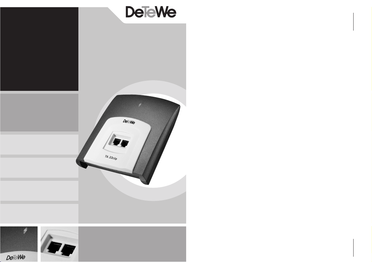
TA 33clip
User Guide
Thank you for deciding to purchase this DeTeWe product. Our
product represents the highest
standards of quality combined
with high-grade design.
This user guide will assist you in
using the TA 33clip, answering
all the most important questions. Should you require any
additional support or information, please contact your dealer.
We hope you enjoy using your
TA 33clip.
Page 2
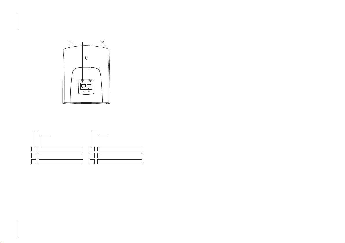
Planning your system
* This is the telephone number
which – unless blocked by your
settings – is displayed on the
called subscriber’s terminal (see
also pages 27 and 35).
In the table opposite, please
enter the telephone numbers
(MSNs*), calls to which are to
be signalled on the corresponding line. The TA33clip can
manage up to six numbers. A
number can be allocated to
more than one line, and each
line can be allocated up to three
numbers.
Analogue lines 1 and 2 and the
telephone numbers are
assigned code digits. These are
required for setting and/or programming the relevant features. Please use this setting aid
to program the TA 33clip (from
page 17 onwards).
* MSN = Multiple Subscriber Num-
ber. These are the ISDN numbers
which you received from your network operator.
Note
After mounting and commissioning the TA 33clip you can
start making and receiving calls
immediately without any programming. To ensure that you
don’t miss a call, all calls are signalled on both lines.
When you make an external
call, the main number of your
ISDN line is transmitted to the
called party by the network
operator.
Please note the settings for the
TA 33clip on delivery listed on
page 38.
Analogue line 1
code digit
Analogue line 1 telephone number
code digits
Your telephone numbers
for line 1
1
2
3
Analogue line 2
code digit
Analogue line 2 telephone number
code digits
Your telephone numbers for line 2
*
1
2
3
*
Page 3

Contents
1
Contents
Safety Precautions 3
Getting to Know Your TA 33clip 5
General 5
Symbols Used 7
Operating Display 7
Mounting and Commissioning 8
Requirements 8
What Is Included? 8
Setting up the TA 33clip/Wall Mounting 9
Connecting the Devices 11
Connecting Analogue Terminals 11
Connecting the TA 33clip to the ISDN 12
Connecting the TA 33clip to the Power Supply 13
Power Supply Socket 14
Setting the Dialling Mode 16
Programming Telephone Numbers 17
Basics 17
Switching the Programming Mode on/off 17
Programming Telephone Numbers for the Analogue Lines 19
Settings for Text Messages (SMS) 21
Example Configuration 22
Making Telephone Calls 24
Displaying the Caller’s Number / Text Messages (SMS) 24
External Calls 24
Internal Calls 24
Enquiry Calls 25
Toggling 25
Page 4

Safety Precautions
3
Contents
2
Ending a Held Call 25
Ending the Current Call 26
Transferring a Call 26
Picking up a Call 26
ISDN Features 27
Temporary Calling Line Identification Restriction for a Call 27
Switching Call Waiting on/off and Checking Call-waiting Status 27
Accepting a Waiting Call and Putting the Current Call on Hold 28
Accepting a Waiting Call and Disconnecting the Current Call 28
Rejecting a Waiting Call 29
Three-party Conference 29
Call Forwarding 30
Callback on Busy 32
Programming Other Settings 34
Switching the Programming Mode on/off 34
Permanent Calling Line Identification Restriction 35
Operation in Telecommunications Systems/Keypad Signalling 36
Resetting All Settings to the Default Options 37
Settings on Delivery 38
Audio Signals and Cadences 39
Troubleshooting 40
Service and Warranty 41
Programming Table 42
Declaration of Conformity 43
Technical Data 43
Glossary 45
Index 47
Drilling Template 49
Safety Precautions
Before you set up or use the TA
33clip ...
...please ensure that you observe
the instructions in this guide. We
are legally required to inform
you of important precautions
you need to take in order to
ensure your own safety and
avoid damage to the TA 33clip
and to other devices.
If these instructions are not
observed, the manufacturer cannot accept any liability for damage arising from negligent or
deliberate disregard of the
instructions in this guide.
Only devices supplying SELV
(safety extra-low voltage) may
be connected to the TA 33clip.
• The correct usage of permitted devices meets this
requirement.
• Do not open the casing.
Unauthorised opening of the
casing and incorrect repairs
may result in risks to the
user. It also renders the warranty null and void.
• Do not allow any liquid to
penetrate into the interior of
the TA 33clip as this could
result in electric shocks or
short-circuits.
• Position the connection
cables so as to prevent accidents.
• Do not install your TA 33clip
- in the vicinity of heat
sources,
- in direct sunlight,
- in the vicinity of other
electrical devices.
• Do not allow the device to
come into contact with
Page 5

Getting to Know Your TA 33clip
5
Safety Precautions
4
damp, dust, caustic liquids or
vapour.
• Plug the connection cables
only into the appropriate
sockets .
• Connect only permitted
accessories to the device.
• Use only the AC adapter supplied, part no. 4505617.
• Use only a slightly damp
cloth to clean the device
• Do not use the TA 33clip in
damp areas (e.g. bathrooms)
or in areas where there is a
risk of explosion.
Getting to Know
Your TA 33clip
General
The TA 33clip terminal adapter is
used to operate analogue equipment such as telephones
(including DECT base stations),
fax machines (Classes 2 and 3)
and analogue modems (28,800
Baud) on an ISDN basic access.
You can use the two user channels (B-channels) for two independent external calls (e.g. telephone conversations). You can
call someone whilst at the same
time transferring data to a business contact from your PC (using
an analogue modem).
The TA 33clip can be operated
on an ISDN multi-terminal access
using the DSS1 protocol or in a
telecommunications system on
the internal S0bus.
The TA 33clip supports calling
line identification presentation
(CLIP) and the reception of text
messages (SMS) on suitable terminals (depending on the network operator).
In the default setting on delivery, keypad signalling is also
supported. This means that you
can control features on the
ISDN network (for more information, see page 36).
On the TA 33clip you can operate analogue telephones with
dual-tone multifrequency
(DTMF) dialling and flash function (60 to 350-ms flash time
detection) or terminals with
pulse dialling. However, you
can only use the full range of
features on telephones with
DTMF dialling and flash. Pulsedialling telephones do not have
a flash function, a star or a hash
key, all of which are required to
control the TA 33clip features
and/or the features of any
Page 6

Getting to Know Your TA 33clip
7
Getting to Know Your TA 33clip
6
telecommunications system to
which the TA33clip is connected as a sub-system.
The following restrictions apply
when using telephones with
pulse dialling:
• Internal dialling and call pickup are not possible.
• Accepting a waiting call is
only possible by replacing
the handset and raising it
again.
• For all call processing procedures, e.g. toggling, press
the digit “1” instead of the Rkey. However, you cannot
return to the previous status,
e.g. to the held call, by pressing this key again, as you can
with dual-tone multifrequency telephones.
Use of the following ISDN features is only possible using a
telephone with dual-tone multifrequency:
Calling line identification
restriction (CLIR) for a call, setup
or blocking of call waiting (CW),
call forwarding (CFU, CFB,
CFNR) and completion of call to
busy subscriber (CCBS).
When operated on an ISDN
access, the TA 33clip behaves
just like a digital terminal. This
means that up to seven additional digital terminals can be
connected in parallel to the TA
33clip.
Symbols Used
b
Lift the handset
d
Replace the handset
g
Your telephone is ringing
c
Conduct your conversation
r
Press the R-key
*
Press the star key
#
Press the hash key
t
Dial a number or press a
code digit
q
You will hear a tone, e.g.
dialling tone, busy tone,
acknowledgement tone,
call waiting tone, etc.
Operating Display
The LED above the sockets for
the analogue lines is:
• continuously illuminated:
TA 33clip power supply is on.
• flashing: If you hear the busy
tone approx. five seconds
after lifting the handset and
the LED starts flashing, the
ISDN connection cable is not
plugged in or the NTBA is
faulty.
To stop the flashing once you
have successfully connected
to the ISDN, lift the handset,
wait for approx. five seconds
and then replace the handset.
Page 7

Mounting and Commissioning
9
Mounting and Commissioning
8
Mounting and
Commissioning
To install the system, follow the
steps in the order below:
• Check the requirements for
installation
• Familiarise yourself with the
components supplied
• Connect the devices
• Commission the ISDN
adapter
• Program the telephone numbers (MSNs) for the analogue
lines
Requirements
In order to be able to assemble
and commission the ISDN
adapter correctly, you require a
Euro-ISDN basic access using
the DSS1 protocol (for multi-
terminal access), and a network
terminator (NTBA) from your
network operator, installed and
ready for operation. The
adapter is not designed for
operation on a system access
and such operation may cause
faults.
What Is Included?
Check that the contents of your
package are complete:
• One TA 33clip user guide
• One TA 33clip terminal
adapter
• One AC adapter with a 3-m
connection cable
• One ISDN connection cable,
length 3 m
Setting up the TA 33clip
/
Wall Mounting
The correct mounting location
should meet the following
requirements in order for the
device to function safely and
without faults.
Choose a mounting location,
• where there is absolutely no
risk of liquid dripping onto the
device and entering the device
through the vents,
• on a wall which is level and
stable, and
• in an area which is as free of
dust and as dry as possible to
prevent correct functioning
being impaired. It should be
possible to air the room to
ensure that the air remains dry
and no condensation forms
The TA 33clip has been manufactured for normal operating
conditions and is designed as a
table-top device.
Today’s furniture is coated with
a vast array of varnishes and
plastics and is treated with different polishes. This inevitably
means that there is a risk that
some of these substances may
contain components which
damage the rubber feet on the
TA 33clip. In this situation, it is
possible that the feet on the
unit damaged by external substances may leave unsightly
marks on the surface of furniture. The manufacturer cannot
therefore accept any liability for
damage of this nature. Please
position the TA 33clip on a nonslip base.
Page 8

Connecting the Devices
11
Mounting and Commissioning
10
If you would prefer to mount
the device on a wall, the following tools are required:
• 6 mm drill bit for stone (type
of drill depends on the material)
• Drill
• Screwdriver (suitable for the
type of screw being used)
Warning
Ensure that there are no power
lines, cables or similar laid in
the area where you plan to drill
the holes.
To mount the TA 33clip onto
the wall, use the drilling template supplied (see page 49) to
drill two holes approx. 30 mm
deep and insert two plastic
dowels with a diameter of 6
mm. Screw in the screws so that
the distance between the wall
and the screw head is approx.
4.5 mm. The screw shank
should be 3.5 mm thick. Hang
the TA 33clip up on the two
screws. The AC adapter
socket is located on the
underside of the TA 33clip.
Insert the plug of the AC
adapter cable into this socket.
However, do not plug the
adapter into the mains socket
at this point.
Connecting the
Devices
Connecting Analogue
Terminals
On the front of the device you
will find two RJ11 sockets for
analogue terminals.
Avoid using terminals with different dialling modes (pulse
dialling and DTMF) on the same
line (e.g. via an adapter cable).
For more information on this,
see “Setting the Dialling Mode”
on page 16.
RJ11 socket for
analogue line 1
RJ11 socket for
analogue line 2
Sockets for telephone, fax
machine, answering machine
or analogue modem.
Page 9

Connecting the Devices
13
Connecting the Devices
12
Please note
Pulse-dialling terminals must
be checked in using a specific
procedure in order to be
detected automatically (see
page 16).
Please do not use any connection cables longer than 3
metres for analogue terminals.
Connecting the TA
33clip to the ISDN
The TA33clip has a general connection licence. This means that
anyone may connect the device
to the operator’s telephone network, but only if the following
conditions are met:
• The device is only designed
for the ISDN basic access S
0
bus. Never connect the
device to lines or devices in
an analogue network. This
could result in malfunctions
and/or damage both to the
ISDN adapter and to the network.
• The Euro-ISDN basic multiterminal access must be
equipped with a network terminator (NTBA) from your
network operator.
You will find the ISDN connection socket for the ISDN connection cable supplied on the
underside of the device. Connect this to the network terminator (NTBA).
Connecting the TA
33clip to the Power
Supply
The connection to the 230-V
mains supply can only be carried out without risk if the
instructions below are followed
very carefully.
• Position the mains cable
behind the AC adapter to
ensure that no-one can trip
over it.
• Ensure that the socket and
the AC adapter are easily
accessible so that the
adapter can be unplugged
from the socket quickly in the
event of danger. This is also
necessary because the TA
33clip does not have a separate mains switch. The TA 33
clip can only be completely
disconnected from the mains
by unplugging the AC
adapter.
• Never unplug the adapter by
pulling on the cable. If you
want to disconnect the
device from the power supply, always pull the adapter
itself out of the mains socket.
Caution!
Only use the AC adapter supplied, part no. 4505617. Other
adapters can cause malfunctions or even electric shocks or
material damage.
Warning!
Never operate or continue to
operate the device if the AC
adapter is damaged.
This could be life-threatening
due to risk of electric shock.
Page 10

Connecting the Devices
15
Connecting the Devices
14
If the AC adapter plugged in is
damaged:
• First turn the power off at the
mains before unplugging the
AC adapter.
• The AC adapter must not be
repaired. Purchase a new
adapter from your supplier if
you notice any sign of damage.
• Never remove the AC
adapter supplied from its
connection cable. This could
be life-threatening due to
electric shock. Use a suitable
extension cable from a specialist dealer if the adapter
plug cable cannot reach a
socket.
Power Supply Socket
Telecommunications systems
can be affected by interference
from the power supply originating from other electrical
devices. This is a known issue
with photocopiers, laser printers, electric typewriters, air conditioning units, fan heaters,
vacuum cleaners and refrigerators in particular. For this reason, the following points must
be observed:
• Connect the TA 33clip to a
socket which is as far away as
possible from the sockets for
the devices mentioned
above. The ideal situation
would be to have a separate
power supply for the TA
33clip.
• Ensure that the AC adapter is
safely and securely inserted
into the socket at all times.
Loose plugs and sockets represent a fire hazard.
Such danger spots must be
repaired immediately by an
electrician.
• Use only socket adapters
with an adequate level of
safety. This can only be guaranteed for adapters with a
safety registration code displayed on the outside (e.g.
with the CE symbol, previously the GS symbol for
approved safety). Otherwise
malfunctions may occur
when operating the TA
33clip, including a risk of fire
in the event of a fault.
Note
Provide a separate power supply to the 230-V connection for
the TA 33clip. This excludes the
risk of short circuits from other
existing devices rendering the
TA 33clip non-operational.
To protect against surges,
which can occur during thunderstorms, it is advisable to
install a surge protection
device. Contact an electrician
for specialist advice.
Following correct assembly and
installation, connect the TA
33clip to the power supply. The
AC adapter socket is located on
the underside of the TA 33clip.
Insert the AC adapter cable plug
into this socket. Then plug the
adapter into the mains socket.
If the LED is continually illuminated, the TA 33clip is connected to the power supply.
In the event of an error, please
first attempt to rectify the fault
using the “Troubleshooting”
table.
Page 11

17
Programming Telephone Numbers
Programming
Telephone
Numbers
Basics
As the TA 33clip is supplied as a
“plug & play” device, it is only
necessary to program it for specific purposes, e.g. if you want
to set up a fax machine with a
separate number on your TA
33clip. In the default setting, all
calls are signalled on both analogue lines. Your ISDN access
normally includes three numbers (MSNs), but you can order
more from your provider.
Switching the
Programming Mode
on/off
Before you can carry out any
programming on the TA 33clip,
you need to switch the programming mode on. This then
remains active for 15 minutes
before being switched off automatically. You can also switch
the programming mode off
manually by entering a code.
Please note that whilst the programming mode is active, no
outgoing or incoming calls are
possible on any of the terminals
connected to the TA 33clip.
Programming is carried out
using a DTMF telephone which
is plugged into one of the RJ11
sockets on the front. This telephone is also used to switch the
programming mode on.
Switching the programming
mode on:
b
r * 8
0 0 0 0
# q
d
Connecting the Devices
16
Setting the Dialling
Mode
• Analogue devices using the
DTMF dialling mode and
flash function are detected
automatically. No settings
need to be made.
• Analogue devices using
pulse dialling must be
checked in before being used
for the first time. To do this,
lift the telephone handset
and press any digit other
than “1.” Replace the handset. The dialling mode will be
detected automatically.
If at a later stage a DTMF signal
is detected on a line which has
been set for pulse dialling, the
TA 33clip will automatically
switch back to DTMF operating
mode. It is therefore advisable
to avoid using hand-held transmitters or signal transmitters
for the remote querying of
answerphones on devices using
pulse dialling.
Page 12

19
18
Programming Telephone Numbers
Programming the
Telephone Numbers for
the Analogue Lines
You can allocate telephone
numbers to each of the two
analogue lines. Calls for these
numbers are then signalled on
the terminals connected to the
respective analogue line, i.e. on
the terminals plugged into this
RJ11 socket. A maximum of
three telephone numbers (making a total of six) can be programmed for each analogue
line. The telephone numbers
are assigned the codes “1,” “2”
and “3” for each line.
The lines are assigned the codes
“1” for line 1 and “2” for line 2.
Open out the front gatefold
page “Planning Your System”
and note down the relevant
numbers.
Programming the Telephone
Numbers for Analogue Line 1
Program the first number using
the following key sequence.
b
Lift the handset.
1
Press the code digit “1” for
line 1.
1
Press the programming
2
code digits (“1” and “2”).
t
Press the telephone number code digit.
t
Enter the telephone number (without your area
dialling code).
#
Press the hash key.
q
You will hear the acknowledgement tone.
d
Replace the handset.
Telephone numbers can be up
to 12 digits long.
Programming Telephone Numbers
Switching the programming
mode off:
b
8 # q
d
Once you have switched the
programming mode on, you
start programming the individual numbers by lifting the
handset. After a few seconds
you will hear a series of very
short high-pitched tones (this is
the programming tone). Your
inputs have been saved once
you hear a low-pitched tone for
one second (positive acknowledgement tone). Invalid inputs
are rejected with three short
high-pitched tones (negative
acknowledgement tone). You
end the programming
sequence by replacing the
handset. Replacing the handset
before acknowledgement will
cancel the programming
process.
Please do not forget to switch
the programming mode off
again when you have finished
programming.
Note
To program the TA 33clip without access to the ISDN, you will
need to wait for approx. five
seconds after replacing the
handset before following the
procedure described on pages
17 and 34.
Page 13

21
20
Programming Telephone Numbers
Settings for Text
Messages (SMS)
If you are operating an SMScompatible telephone on your
access, a different telephone
number should be programmed for each line under
the telephone number code
digit “1” (see gatefold cover
page of this user guide). The
reason for this is to prevent the
second telephone ringing when
a text message is received. The
number display function (CLIP)
must not be switched off as
otherwise it is not possible to
send text messages.
Programming Telephone Numbers
If necessary, program a second
and third number for the line.
If you hear negative acknowledgement tone, an error has
occurred during the input
process.
Please repeat the input.
If you want to delete a programmed telephone number,
enter the code digit for that
telephone number (“1,” “2” or
“3”) and then press the hash
key straight away.
Programming the Telephone
Numbers for Analogue Line 2
Program the first number using
the following key sequence.
b
Lift the handset.
2
Press the code digit “2” for
line 2.
1
Enter the programming
2
code digits (“1” and “2”).
t
Press the telephone number code digit.
t
Enter the telephone number (without your area
dialling code).
#
Press the hash key.
q
You will hear the acknowledgement tone.
d
Replace the handset.
Telephone numbers can be up
to 12 digits long. If necessary,
program a second and third
number for the line.
If you want to delete a programmed telephone number,
enter the code digit for that
telephone number (“1,” “2” or
“3”) and then press the hash
key straight away.
Page 14

23
22
Programming Telephone Numbers
Programming the example
configuration: analogue line 2
On the right-hand RJ11 socket
(analogue line 2) you want to
operate another analogue telephone (e.g. cordless DECT telephone) with the number
“4711.” This telephone number
has been assigned the code
digit “1.”
Edit the setting as follows:
b
2
Line code digit
1 2
Programming code digit
1
Telephone number code
digit
t
Telephone number
(“4711”)
#
q
d
Then switch the programming
mode off again (see page 18).
A maximum of six telephone
numbers can be programmed,
three for each line.
Other numbers can be used for
ISDN terminals (in the example,
a PC with an ISDN card) which
are connected directly to the
NTBA or the S0bus. Programming here is then carried out on
the terminals themselves.
Note
In order for your network operator to provide billing for specific telephone numbers, the
telephone number used to
make a call is important. The
telephone number programmed under the code digit
“1” is always used for this purpose. If no telephone number is
programmed under this digit,
the call will be billed under the
main number for your access.
Programming Telephone Numbers
Example Configuration
PC with ISDN card;
Number (MSN), e.g. “4713”
Analogue DECT telephone;
Number (MSN), e.g. “4711”
Analogue telephone;
Number (MSN), e.g. “4712”
Programming the example
configuration: analogue line 1
You want to operate an analogue telephone with the telephone number “4712” on the
left-hand RJ11 socket (analogue
line 1).
This telephone number has
been assigned the code digit
“1.”
Plug a DTMF-compatible telephone into any socket and
switch the programming mode on
(see page 17).
Then edit the setting as follows:
b
1
Line code digit
1 2
Programming code digit
1
Telephone number code
digit
t
Telephone number (“4712”)
#
q
d
Page 15

25
24
Making Telephone Calls
b r * *
The device on the other analogue line is called.
Enquiry Calls
A call can be interrupted to
make an enquiry call to an
internal or external user:
c r q
* *
= internal telephone
number
or
t
external telephone number
c
You speak to the second subscriber and the first subscriber is
put on hold.
Enquiry calls cannot be made
on both lines simultaneously.
After pressing the R-key you
will hear the signal tone if, for
example, you toggle between
calls.
Toggling
You conduct an external conversation, initiate the enquiry
call and dial the new number.
The first call is put on hold. By
pressing
r 2
you can toggle
back and forth between the
calls:
c r q
* *
= internal telephone
number
or
t
external telephone number
c
Toggle using
r q 2 c
Ending a Held Call
You are conducting a conversation and another call is being
held:
c r q 0 c
Making Telephone Calls
Making Telephone
Calls
Displaying the Caller’s
Number / Text
Messages (SMS)
This function is also known as
CLIP (Calling Line Identification
Presentation) and must be supported by your network operator. In addition, the number has
to be transmitted by the caller
and your terminals must be
equipped for this function. If
required, contact your network
operator to order the CLIP service. The CLIP function is also
required if you want to receive
text messages (SMS) using suitable terminals.
External Calls
b
Lift the handset.
t
and dial the external
telephone number.
External calls can be made on
both analogue lines simultaneously. Incoming calls for all
numbers are signalled on both
lines unless you have programmed your TA 33clip differently. No charge pulses are sent
to the analogue terminals.
Note
During a call via DTMF signalling it is advisable to avoid
using hand-held transmitters
for the remote querying of
answerphones on devices using
pulse dialling. This will block
your device for any further
dialling and it will need to be
re-enabled by dialling any digit
other than “1” (see also page
16).
Internal Calls
You can make internal calls free
of charge between the two
telephones.
Page 16

27
ISDN Features
ISDN Features
If your inputs for setting the
features were successful, you
will hear the positive acknowledgement tone (low-pitched
tone for one second). Invalid
inputs are rejected with the
negative acknowledgement
tone (three short high-pitched
tones). Certain inputs are
acknowledged with tones. A list
with descriptions of all the
tones and cadences can be
found in the appendix.
Temporary Calling Line
Identification
Restriction for a Call
The telephone number stored
under the telephone number
code digit “1” for the line used
to make the call is always transmitted to the called subscriber.
You can temporarily restrict
calling line identification for a
call. This also applies to enquiry
calls made during this call. If you
want to set the calling line identification restriction permanently, you will find the required
settings on page 35.
b r * 3 1 # q
t
(external telephone number)
c
Switching Call Waiting
on/off and Checking
Call-waiting Status
Whilst you are conducting a conversation, another subscriber
may try to call you.
You can switch the call-waiting
function on and off individually
for each line with the connected
terminal.
Switching call waiting on:
b r * 4 3 # q d
26
Making Telephone Calls
The held call is disconnected
and you continue your conversation with the subscriber with
whom you were speaking.
Ending the Current
Call
You are conducting a conversation and another call is being
held:
c r q 1 c
The current call is disconnected
and you continue your conversation with the subscriber who
was formerly being held.
Transferring a Call
You can transfer an external call
to the other internal user.
You are conducting an external
conversation:
c r q * * c d
You can wait until the other
internal subscriber answers,
announce the call and then
replace the handset.
You can also replace the handset after pressing the star key
twice.
The other internal subscriber is
then called. When this person
lifts the handset, he or she will
be connected with the external
subscriber. If the other internal
subscriber does not answer
after max. two minutes, the call
on hold with the external subscriber is disconnected.
Picking up a Call
If the other telephone rings,
you can pick up the call:
g b r q
(signal tone)
4
c
You are connected with the
caller.
Page 17

29
28
ISDN Features
Rejecting a Waiting
Caller
You are conducting a conversation and another subscriber
calls you. You hear the call waiting tone:
c q r q 0 c
You continue your conversation
with the first subscriber. The
waiting caller is rejected.
Three-party
Conference
You can speak to two external
subscribers at the same time, in
other words, you can hold a
three-party conference.
For technical reasons it is not
possible to hold a three-party
conference with one external
subscriber and the other internal subscriber on the TA 33clip.
In a three-party conference the
second line on the TA 33clip is
not available; another terminal
on the TA 33clip cannot therefore make any calls.
Other terminals on the ISDN
access or internal S0bus on a
telephone system can make or
take calls on the second channel (B-channel).
You are conducting a conversation and another subscriber is
on hold.
Initiating a three-party conference
You are conducting an external
conversation. You initiate the
enquiry call and dial the new
telephone number. The first call
is put on hold. The conference
is initiated by pressing the Rkey and the digit “3.”
ISDN Features
Switching call waiting off:
b r # 4 3 # q d
Checking the call-waiting status:
b r * # 4 3 # q d
Call waiting on: positive
acknowledgement tone
Call waiting off: negative
acknowledgement tone
Accepting the Waiting
Call and Putting the
Current Call on Hold
You are conducting a conversation and another subscriber
calls you. You hear the callwaiting tone:
c q r q 2 c
You speak to the waiting caller
and the current call is placed on
hold. You can return to the held
call by using
r1
or you can
toggle between the two calls
using
r 2
(see page 18).
Accepting the Waiting
Call and Disconnecting
the Current Call
You are conducting a conversation and another subscriber
calls you. You hear the call waiting tone:
c q r q 1 c
You speak to the waiting caller
and the current call is disconnected.
Or:
d g b c
Replace the handset. The current call is disconnected. Your
telephone rings. You lift the
handset and speak to the waiting caller.
Page 18

31
30
ISDN Features
For an overview, please refer to
the front gatefold to check your
programming options.
In the following procedures you
must always enter your complete telephone number, and
not merely the code digit for
that telephone number. The
destination telephone number
must be prefixed by the area
dialling code.
Switching call forwarding on:
b r * t
(CF code digits)
t
(your telephone number)
* t
(destination telephone
number)
# q d
Switching call forwarding off:
b r # t
(CF code digits)
t
(your telephone number)
# q d
Checking call forwarding:
b r * # t
(CF code dig-
its)
t
(your telephone num-
ber)
# q d
If call forwarding is activated,
you hear the positive acknowledgement tone; if not, you hear
the negative tone.
ISDN Features
c r q t
External number
c
Initiate the conference using
r q 3 c
You speak to both subscribers
at the same time.
Ending the three-party conference:
c r q 2 c
You are reconnected to the subscriber with whom you last
spoke before the conference.
The other subscriber is put on
hold. The call on hold or the
current call can be ended as
described on page 26. If you
want to end both calls simultaneously, replace the handset
during the three-party conference.
Call Forwarding
You can forward calls intended
for you to a different telephone
number.
There are various different ways
of doing this. All call forwarding
options are set individually for
each line on the respective
terminal. There are three types
of call forwarding which can be
selected by entering the relevant call forwarding (CF) code
digits.
• Immediate call forwarding
CF code digits “21”
• Call forwarding on busy
CF code digits “67”
• Call forwarding on no reply
CF code digits “61”
In order to use the call-forwarding function, your telephone
numbers must be programmed
for the respective analogue line
(see page 17ff).
Page 19

33
32
ISDN Features
Cancelling callback on busy
You want to cancel a callback
request:
b r # 3 7 # q d
You will hear the positive
acknowledgement tone if the
callback request has been cancelled.
ISDN Features
Checking the destination
number:
b r * # t
(CF code dig-
its)
t
(your telephone num-
ber)
* t
(destination tele-
phone number)
# q d
If the correct destination number is entered, you hear the
positive acknowledgement
tone; if not, the negative tone.
In this case you will need to
switch the call forwarding feature back on again by entering
the desired destination number.
Deleting all call forwarding
settings:
b r # 0 0 # q
(after a
few seconds)
d
All call forwarding settings for
the ISDN access will be deleted.
Callback on Busy
This function must be supported by the network operator, and ordered if necessary.
You have called an external
user. The line is busy and you
hear the special busy tone.
If you do not hear the special
busy tone, the callback on busy
option cannot be used.
Requesting callback on busy:
c q * 3 7 # q d
You will hear the positive
acknowledgement tone if the
callback request has been
accepted. As soon as the line
becomes free, your telephone
will ring.
When you lift the handset, the
previously busy subscriber is
called.
Page 20

35
34
Programming Other Settings
(negative acknowledgement
tone). End the programming
sequence by replacing the
handset. Replacing the handset
before acknowledgement will
cancel the programming
process.
Please do not forget to switch
the programming mode off
again when you have finished
programming.
Permanent Calling
Line Identification
Restriction
When you make an outgoing
call, your telephone number is
transmitted to the called terminal, assuming that that terminal
supports calling number display. In the default setting, the
TA 33clip is configured to transmit the telephone number. You
can permanently restrict or
enable transmission.
To restrict the transmission of
your own telephone number:
b t
(line code digit) and
8 0 1 q d
Line code digit: “0” for both
lines, “1” for line 1, “2” for line 2
Programming Other Settings
Programming
Other Settings
Switching the
Programming Mode
on/off
Before you can carry out any
programming on the TA 33clip,
you need to switch the programming mode on. This then
remains active for 15 minutes
before being switched off automatically. You can also switch
the programming mode off
manually by entering a code.
Please note that whilst the programming mode is active, no
outgoing or incoming calls are
possible on any terminals connected to the TA 33clip.
Programming is carried out
using a DTMF telephone which
is plugged into one of the RJ11
sockets on the front. This telephone is also used to switch on
the programming mode on.
Switching the programming
mode on:
b r * 8
0 0 0 0
# q d
Switching the programming
mode off:
b 8 # q d
Once you have switched the
programming mode on, you
start the individual programming procedures by lifting the
handset. After a few seconds
you will hear a series of very
short high-pitched tones (programming tone). Your inputs
have been saved once you hear
a low-pitched tone for one second (positive acknowledgement tone).
Invalid inputs are rejected with
three short high-pitched tones
Page 21

37
36
Programming Other Settings
Only one of the following
options can be active at any one
time.
Operation on telecommunications systems:
b 0 3 0 q d
Operation on an ISDN basic
access (NTBA) without keypad
signalling:
b 0 3 1 q d
Operation on an ISDN basic
access (NTBA) with keypad signalling:
b 0 3 2 q d
Resetting All Settings
to the Default Options
All the settings can be reset to
the original settings on delivery:
b 0 0 0 q d
Programming Other Settings
To re-activate the transmission of your own telephone
number:
b t
(line code digit) and
8 0 0 q d
Line code digit: “0” for both
lines, “1” for line 1, “2” for line 2
Operation in
Telecommunications
Systems / Keypad
Signalling
If you operate the TA 33clip on
the internal S0access of a
telecommunications system,
you can change the operating
mode. The telephones on the
TA 33clip then behave like the
other telephones in the
telecommunications system.
Please refer to the operating
instructions for your telecommunications system to find out
which code digits you can use
to make calls to other tele-
phones and for information on
how to make external calls.
With this setting, it is then not
possible to make internal calls
and use other features of the TA
33clip.
When the TA 33clip is operated
on an ISDN basic access, you
can specify whether or not keypad signalling is activated.
Keypad signalling is used to
control special functions on the
ISDN network (e.g. you can
block certain lines and numbers
yourself). If this operating mode
is set, it is possible to switch
over to keypad signalling whenever you press the star key or
the hash key after lifting the
handset, as all keypad procedures start with one of these
keys.
Contact your network operator
for information as to whether or
not keypad signalling is supported and on the range of
services available.
Page 22
39
38
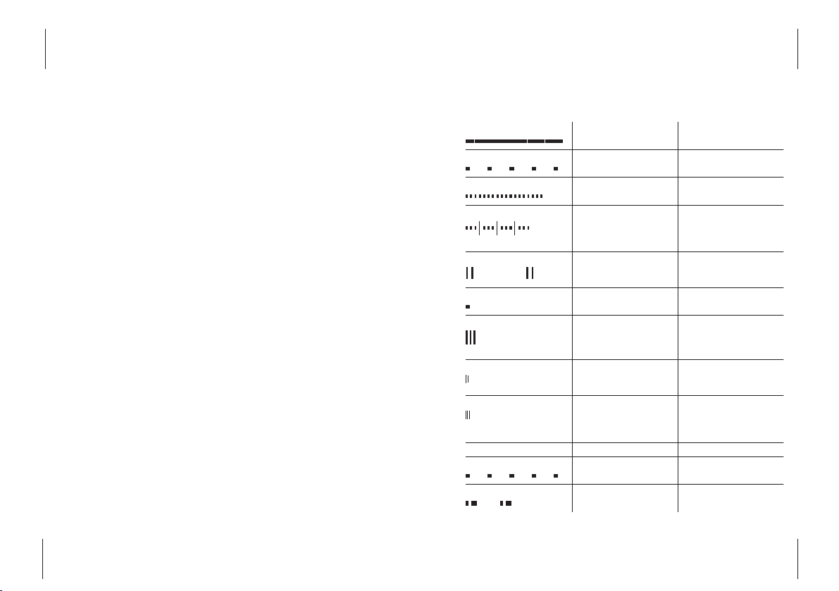
Audio Signals and Cadences
Programming Other Settings
Audio Signals and Cadences
Settings on Delivery
• All telephone numbers are
deleted.
• The main number for your
ISDN access is transmitted to
the called subscriber.
• Operation on telecommunications systems is deactivated (see page 36).
• Call waiting is activated (see
page 27).
• All calls are signalled on both
lines.
• Pulse-dialling telephones are
not checked in (see page 16).
• Keypad signalling is active.
Dialling tone
Call signalling
Busy tone
Special busy tone
Call-waiting tone
Positive acknowledgement tone
Negative acknowledgement tone
Signal tone
Programming tone
External call signalling
Internal call signalling
Continuous tone, 425 Hz You can dial a number
1s T one, 425 Hz,
4s Pause
0,25s Tone, 425 Hz, The subscribe r you
0,25s Pause
3x 0, 5s Tone, 425 Hz, 0,5 s
Pause, 0,1s Tone, 425 Hz,
0,9 s Pause
0,1s Tone, 425 Hz,
0,25s Pause, 0,1 s Tone
425 Hz, 3s Pause
1s Tone, 425 Hz Positive acknowledgement
0,3 s Tone 1600 Hz, 0,3 s
Pause, 0,3 s Tone 1600 Hz,
0,3 s Pause, 0,3 s Tone
1600 Hz
0, 25 s Tone 1600 Hz, 0,25s
Pause, 0,25s, Tone, 1600 Hz
0, 2s Tone, 1600 Hz
0, 2 s Pa use, 0, 2s Tone 1600
Hz , 0,2s Pause, 0,2s Tone
1600 Hz,
1s Call, 4s Pause External call
0, 5s Call, 0,5s Pause
1s Call, 4s Pause
Another subscriber is
being called
called is busy
The subscriber you
called is busy.
You can activate a
callback request.
You are conducting a
conversation when you
receive a second call
of a programming action
A programming action
has been rejected
After pressing the R-key
when in the call state
Programming mode has
been switched on.
Call from the other
analogue line
Page 23

41
40
Guarantee Conditions
Guarantee
Conditions
The guarantee conditions for
this device are as defined by our
representative in your country
in which it is sold. Details
regarding these conditions can
be obtained from the dealer
from whom the device was purchased. The bill of sale or
receipt must be produced when
making any claims under the
terms of this guarantee.
Troubleshooting
Troubleshooting
If your device is no longer functioning as you would wish, first
use the following list to try and
solve the problem yourself. If
your device still isn’t working
properly after this, please contact your dealer’s customer
service department.
Fault
Fault tone (highpitched, short tone)
No connection possible
LED is off
LED is flashing
No calls can be made
to the device
Cause
- Programming error
- One of the connection cables is not
plugged in properly
- Programming mode
is active
- No power supply
- Connection cable to
the ISDN not
plugged in or defective
- Wrong number programmed
- Programming mode
is active
Remedy
- Begin the programming process again
- Check that all plugs
are seated correctly
- Switch the programming mode off
- Plug in the AC
adapter
- Plug the connection
cable in firmly
- Stop the LED from
flashing by lifting
the handset, waiting
approx. five seconds,
and then replacing
the handset
- Re-program
- Switch the programming mode off
Page 24

43
42
Declaration of Conformity
Declaration of Conformity
The EC Declaration of Conformity can be viewed on the Internet at
http://www.detewe.de.
Technical Data
Supply voltage 230 V / 50 Hz via AC adapter
Rated output 3 VA
Protection class 2
ISDN access Euro-ISDN basic access with DSS-1
protocol or internal S0bus on
telecommunications systems
Access type Multi-terminal access
Two analogue ports RJ11 sockets
Pin 2: b, Pin 3: a, Pin 4: b
Connection cable max. 3 m in length
to the telephone
Dialling mode Pulse dialling* , DTMF with flash
function
* with limited functions
Programming Table
Programming
Table
Please enter the settings you
have programmed here and
cross out any points which do
not apply. Settings on delivery
are shown in bold print.
Analogue line 1 Analogue line 2
Line code digit “1” Line code digit “2”
First telephone number:
Telephone number code digit “1”
Second telephone number:
Telephone number code digit “2”
Third telephone number:
Telephone number code digit “3”
Call waiting
on
/ off
on
/ off
Calling line identification
(first telephone number
for the line)
on
/ off
on
/ off
Operation on telephone systems
or
Operation on an ISDN basic
access without keypad
or
Operation on an ISDN basic
on
access with keypad
Page 25

45
44
Glossary
Glossary
a/b line
Line for analogue terminals
using RJ11 sockets.
CLIP (Calling Line Identification Presentation)
Display of the calling subscriber’s number on suitable
terminals (this feature depends
on whether the number is
transmitted and whether this
service is provided by the network operator).
DTMF dual-tone multifrequency
Dialling via internationally standardised tones of different
pitches assigned to the digit
keys and the star and hash keys.
This means that functions at the
exchange can be controlled,
e.g. callback on busy, and
answerphones can be operated
remotely.
Flash function
Function of the R-key or, where
applicable, of another key on
your terminal (flash detection
of the TA 33clip: 60 to 350 ms).
Keypad signalling
For controlling special functions
on the ISDN network (if provided by the network operator,
see also page 36).
Line code digit
Code digit assigned to the a/b
lines (0, 1 or 2).
MSN
With your ISDN basic connection, your operator provides
you with several telephone
numbers (Multiple Subscriber
Numbers) which can be allocated to different terminals.
Pulse dialling
Dialling mode via electrical
pulses; no input via the star and
hash keys is possible.
Technical Data
Flash time detection 60 ms to 350 ms
Data rate for connected
analogue modems 28.8 kbit/sec
analogue fax machines 14.4 kbit/sec
Permissible temperatures
Stationary, weather-proof + 5 °C to + 40°C
Dimensions (W x H x D) 130 mm x 163 mm x 40 mm
Weight (TA 33clip only) approx. 200 g
Page 26

47
46
Stichwortverzeichnis
A
Assembly ...............................8, 9
Audio signals and cadences .39
C
Callback on busy ....................32
Caller’s number ......................24
Call forwarding .......................30
Call pick-up .............................26
Call waiting ..............................27
CLIP .......................................5, 45
Commissioning .........................8
Configuration ..........................22
Connecting analogue
terminals ..................................11
Connecting the TA 33clip
to the ISDN ..............................12
Connecting the TA 33clip
to the power supply ..............13
Customer service ....................40
D
Declaration of conformity ....43
Dialling mode .........................16
Display calling line number ..24
E
Ending a call on hold .............25
Ending the current
conversation ...........................26
Enquiry .....................................25
Example configuration ..........22
External call .............................24
F
Faults ........................................40
Flash function......................5, 45
G
Glossary.....................................45
I
Internal call .............................24
ISDN features ..........................27
K
Keypad signalling ...................36
L
LED ..............................................7
M
Making telephone calls .........24
MSN ...........................................45
Glossary
SMS (Short Message Service)
SMS are text messages which
you can receive on suitable terminals. The prerequisite is that
your network operator supports
SMS and CLIP.
Telephone number code digit
The code assigned to the telephone numbers (MSNs).
Page 27

49
Index of Key Words
48
Drilling Template
Hole spacing
93 mm
✃
Drilling Template
!!! Danger !!!
Before drilling, ensure that there
are no pipes or cables located at
the drilling points. There is a risk
of fatal injury or material damage
if gas, electricity, water or sewage
cables and pipes are damaged.
O
Operating display .....................7
Operation on telecommuni-
cations systems ......................36
P
Packet contents ........................8
Permanent calling line
restriction .................................35
Picking up calls........................26
Programming mode ........17, 34
Programming table ...17, 34, 42
R
Reset all settings ....................37
S
Safety precautions ...................3
Service ......................................41
Settings for text messages ...21
SMS ..........................5, 21, 24, 46
Socket .......................................14
Status on delivery ..................37
Symbols ......................................7
T
Technical data .........................43
Telephone numbers for ana-
logue lines ...............................19
Temporary calling line
identification restriction
for a call ...................................27
Text messages ........................24
Three-party conference ........29
Toggling....................................25
Transferring a call ...................26
Troubleshooting .....................40
W
Wall mounting.........................10
Warranty ..................................41
Page 28

DeTeWe AG & Co. KG · Zeughofstrasse 1 · D-10997 Berlin · Germany · www.detewe.de
Mat. no. 70169.016
As of 06/03
The right to technical modifications is reserved.
 Loading...