

Page 1

Model 700
Remote Sensor/Alarm Relay Module
Operator’s Installation and Instruction Manual
Page 2

700 RAM I.M.
This page left intentionally blank
700 RAM I.M. ii
Page 3

700 RAM I.M.
Table of Contents
1. Introduction ..................................................................................................................................................1
1.1 Description.......................................................................................................................................... 1
1.2 Installation........................................................................................................................................... 1
1.3 Field Wiring........................................................................................................................................ 3
2. Operator Interface.........................................................................................................................................5
3. Set-up and Normal Operation.......................................................................................................................7
3.1 View Sensor Status............................................................................................................................. 8
3.2 Set AutoSpan Level ............................................................................................................................ 8
3.3 Set Serial ID........................................................................................................................................ 9
3.4 Set-up for Relay Outputs .................................................................................................................... 9
3.5 Signal Output Check......................................................................................................................... 10
4. RS-485 Modbus™Protocol.........................................................................................................................11
5. RAM Electronics Warranty........................................................................................................................11
6. Specifications .............................................................................................................................................12
6.1 Spare Parts........................................................................................................................................ 12
6.2 Revision Log......................................................................................Error! Bookmark not defined.
Table of Figures
Figure 1 700 RAM ............................................................................................................................................... 1
Figure 2 RAM Mounting...................................................................................................................................... 2
Figure 3 Mounting RAM with 700 Sensor........................................................................................................... 2
Figure 4 Exploded View of Assembly................................................................................................................. 3
Figure 5 Interface connections on terminal board................................................................................................ 3
Figure 6 Installation with 700 Gas Sensor ........................................................................................................... 4
Figure 7 Remote 700 Gas Sensor with RAM....................................................................................................... 4
Figure 8 RAM Software Flowchart...................................................................................................................... 7
700 RAM I.M. iii
Page 4

This page left intentionally blank
700 RAM I.M.
700 RAM I.M. iv
Page 5
700 RAM I.M.
NOTE:
1. Introduction
1.1 Description
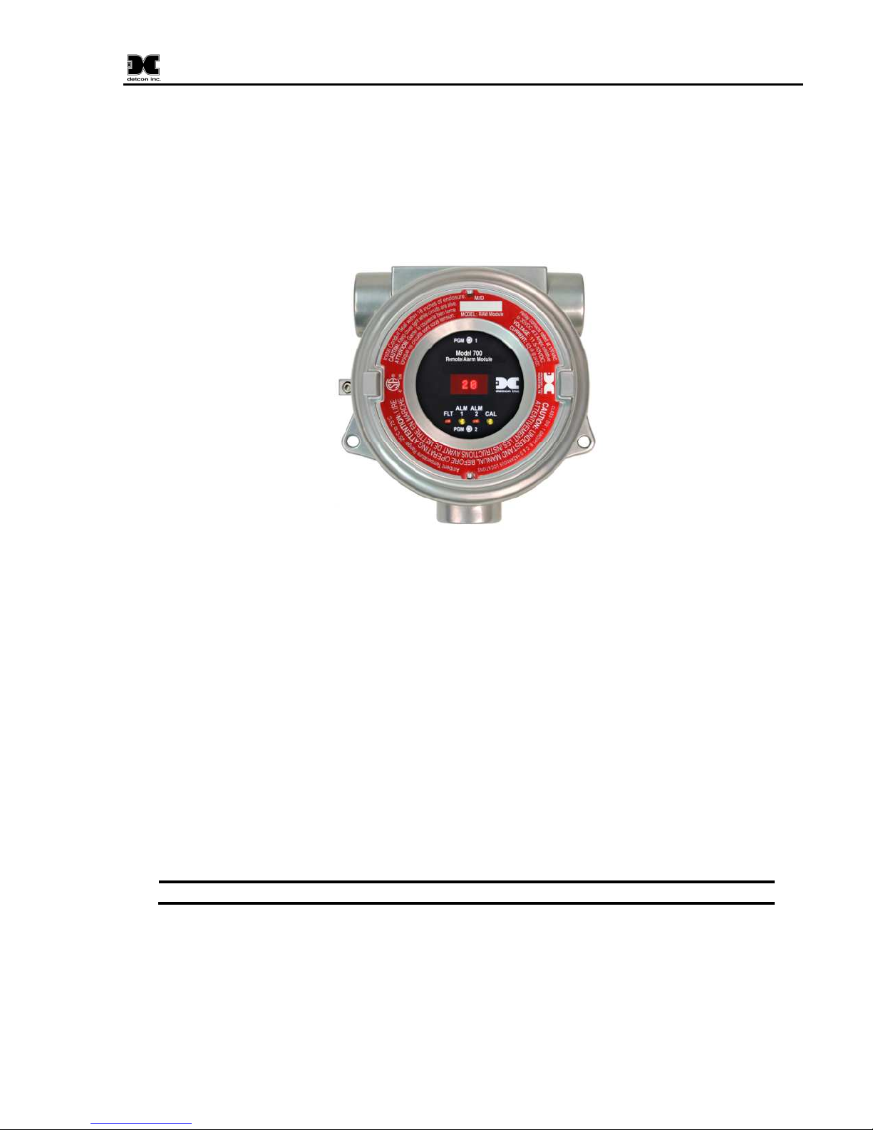
The Model 700 Remote Sensor/Alarm Relay Module (known as the Remote Alarm Module or RAM) is sold
separately as an accessory for Model 700 Gas Sensors. It is a universal design and can be used with any of
the Model 700 Gas Sensors. The RAM is provided in an explosion-proof junction box constructed of either
epoxy-painted aluminum (Figure 1) or 316 stainless steel and includes a glass-viewing window.
Figure 1 700 RAM
The RAM performs two main functions. The first function is to set gas alarm levels and to configure the
three local relay contacts. The second function is to operate a Model 700 Gas Sensor remotely. The remote
sensor function is typically used when the sensor must be mounted in a position where it cannot be viewed or
accessed readily. Both functions can be used at the same time.
The RAM provides the 4-20mA output directly from the Model 700 Gas Sensor. The RAM acts as a
Modbus™ master to the Model 700 Gas Sensor in order to display the reading and execute the remote
control functions. It acts as a Modbus™ slave to any master control device and simply repeats the
Modbus™ output from the 700 Gas Sensor it is connected to.
1.2 Installation
The RAM can be installed as a wall mount or pipe mount using the mounting holes of the explosion-proof
junction box. It should be oriented such that the LED display is horizontal. If the 700 Gas Sensor is
mounted directly to the RAM, use 0.5” spacers underneath the mounting holes to provide access clearance
for the 700 Gas Sensor (Figure 3).
Block any unused ¾” NPT holes with the proper Plug. (Detcon P/N 8522-750)
700 RAM I.M. Rev. 1.1 Page 1 of 12
Page 6

700 RAM I.M.
5.825"
5.2"
5.5"
5.5"
5.2"
Three -¾" NPT Fittings
Ø0.2750 x2
Mounting Holes
Explosion Proof Enclosure
Junction-Box
Figure 2 RAM Mounting
¾" NPT x3
4.35"
4.35"
Bolt
Mounting
Wall (or other
mounting surface)
5.825"
Ø0.275 x2
Mounting Holes
Spacer
Bolt
Mounting
Explosion Proof Enclosure
Junction-Box
(Aluminun Junction-Box shown)
12.945"
7.76"
5.195"
Use Spacers to move
the J-Box and Sensor
detcon inc.
MODEL
XX-700
Sensor
2.115"
PGM2
SPAN
PGM1
ZERO
Assembly away from the
wall at least 0.25-0.5" to
allow access to Sensor
Sensor Assembly
PGM2
SPAN
Wall (or other
mounting surface)
Splash Guard
2"
Figure 3 Mounting RAM with 700 Sensor
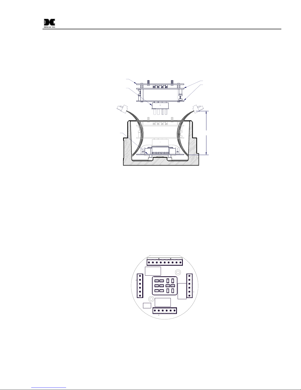
The RAM Electronics package consists of three printed circuit assemblies (PCAs). The top two PCAs (RAM
display and RAM connector board) and the RAM faceplate are enclosed in a molded plastic retaining guard
and can be accessed by removing the junction box cover and using the brass pull knobs to pull the package
directly out of the enclosure. The bottom PCA (terminal board) will remain attached to the bottom of the
700 RAM I.M. Rev. 1.1 Page 2 of 12
Page 7
700 RAM I.M.
junction box via two machine screws allowing the RAM display and RAM connector board to unseat from
the 12-pin plug-in connector and provide access to the terminal board connectors (Figure 5). To install the
electronics package, properly align the 12-pin plug-in connector and gently push the RAM in until it is fully
seated to the terminal board. The RAM faceplate will be even with the top of the junction box when installed
properly. The RAM top should be flush with the top of the enclosure before screwing down the junction box
cover.
RAM faceplate
12-Pin Plug-In
Connector
External Wiring
The terminal
board sets on
the stand-offs in
the enclosure
Input Port
Explosion Proof Junction Box
The RAM display and
RAM connector board
Note: Retaining Guard
removed for clarity
Provide at least
a 6" Service
6"
Loop for all
wiring
Input Port
Figure 4 Exploded View of Assembly
1.3 Field Wiring
The field wiring connections are made to the bottom PCA (terminal board) of the RAM using a series of
connector blocks. There is a 6-pin terminal block for connection to the 700 Gas Sensor (labeled SENSOR), a
9-pin terminal block for connection to the 3 relay contacts (labeled RELAY OUTPUT), a 6-pin terminal
block for connection of power, mA output and Modbus™ interface to the host device (labeled IN) and a 6pin terminal block for connection of power and Modbus™ interface to an additional device (labeled OUT).
Input Power and
Interface to Host
The user will typically connect the 700 Gas Sensor directly to the RAM if there is no requirement for remote
sensor separation (Figure 6). In this case, the 700 sensor will not require its own junction box and it is not
700 RAM I.M. Rev. 1.1 Page 3 of 12
Alarm Relay
Connections
ALM1ALM2 FLT
NO NC COM NO NC COM NO NC COM
J7
mA Output
Modbus™
K1
J2
+
mA
A
B +
IN
U1
K2
J1
+
A B
mA
SENSOR
J4
B
A
K3
OUT
700 Sensor
Connections
Figure 5 Interface connections on terminal board
Modbus™
Interface
Output
Power
Page 8

700 RAM I.M.
NOTE:
NOTE:
necessary to install/use the Transient Protection Module shipped with the 700 sensor. The 700 sensor may
arrive from the factory pre-assembled with the RAM in the j-box, but only if it is ordered in this
configuration. In this configuration, the wires from the 700 sensor will be directly connected to the 6-pin
terminal block labeled “SENSOR” on the terminal board.
If the 700 sensor and RAM are directly connected, it is not necessary to install/use the
Transient Protection Module that is shipped with every 700 Gas Sensor.
Power Input
Fault
Annunciator
mA Output
Alarm 1
Modbus™ Interface
Annunciator
Alarm 2
Annunciator
detconinc.
MODEL
XX-700
PGM2
PGM1
SPAN
ZERO
Sensor
Figure 6 Installation with 700 Gas Sensor
If remote sensor separation is required, the RAM will be separated from the 700 sensor. Remote separation
distances of up to 1000 feet are possible with the recommended cables.
It is highly recommended to install the interconnecting cabling inside rigid metal
conduit to eliminate potential EMI and RFI interference.
Power Input
mA Output
Modbus™ Interface
Figure 7 Remote 700 Gas Sensor with RAM
The recommended cable for remote sensor separation is Belden 8770 (18AWG shielded 3-wire cable) for
connection of power and mA signal return and Belden 9841 (24AWG shielded twisted pair) for serial
Modbus™ communications.
700 RAM I.M. Rev. 1.1 Page 4 of 12
700 RAM
Module
Power & Modbus™
Cabling to/from
Remote 700 Sensor
Transient Protection
Module in Detcon
standard J-Box
Remote 700 Sensor
detconinc.
MODEL
XX-700
PGM1
PGM2
ZERO
SPAN
Sensor
Page 9

Explosion Proof
NOTE:
NOTE:
NOTE:
Junction Box
with RAM Module
ALM1ALM2 FLT
NO NC COM NO N C COM NO NC COM
J7
K1
J2
+
mA
A B
A(+)
K3
SENSOR
B(-)
A
B +
IN
K2
J1
+
mA
(-)
(+)
mA
Customer
J4
B
A
OUT
Supplied Wiring
Power from and 4-20mA
out to Control Device
Modbus RS-485 to
Host Control Device
Transient Protection Module
(TPM) P/N 500-003087-100
A(+)
(+)
(-)
mA
B(-)
Remote
Explosion Proof
Junction Box
with Sensor
Sensor Assembly
Figure 8 Remote Sensor Wiring
Both the 3-wire power/mA cable and the 2-wire Modbus™ serial communications
cable are required when remote wiring between the RAM and the 700 Gas Sensor.
Blk
Red
(+)mA(-)
Wiring to
700 RAM I.M.
Blu
Grn
Wht
A(+)
B(-)
The same recommended cables should be used for the connection between a
Modbus™ master control device and the RAM. However, if only the 4-20mA signal is being
used by the master/host controller, then only the 3-wire cable is required.
2. Operator Interface
The operator interface of the RAM is very similar to the Model 700 Gas Sensor. It uses the identical LED
display, same programming magnet, and has the same magnetic programming switches (PGM1/ZERO and
PGM2/SPAN). The main difference is that the 700 RAM has LED indicators for the 3 relays (ALM1,
ALM2 and FAULT) and a CAL LED to indicate when the 700 sensor is in calibration or being polled
serially by a master control device.
The gas reading, gas units, and fault status reported by the RAM will mimic that of the 700 Gas Sensor. The
Modbus™ output from the RAM repeats the Modbus™ output from the 700 Gas Sensor.
If the Model 700 Gas Sensor is directly connected to the RAM and junction box, then
the gas sensor operation should be exercised through the 700 Gas Sensor (and not the RAM).
This is the recommended practice since the RAM contains a limited number of sensor
operational control functions. If the RAM and 700 Gas Sensor are separated, then normal
remote gas sensor operation should be exercised through the RAM.
The operating interface is menu-driven via the two magnetic program switches located under the target
marks on the RAM faceplate. The two switches are referred to as “PGM1” and “PGM2”. The menu list
consists of three major items that include sub-menus as indicated below. (Refer to the complete Software
Flow Chart Figure 9)
Normal Operation
Current Reading and Fault Status
700 RAM I.M. Rev. 1.1 Page 5 of 12
Page 10

700 RAM I.M.
NOTE:
Calibration Mode
AutoZero (if applicable)
AutoSpan
Program Mode
View Sensor Status (representative of whichever Model 700 Gas Sensor is attached)
Set AutoSpan Level
Set Serial ID
Alarm 1 Settings
Alarm 2 Settings
Fault Settings
Signal Output Check
The user interface of the RAM is designed to mimic that of the Model 700 Gas Sensor. However, only the
functions deemed critical for normal remote sensor operation are available. The 5 menu functions that are
available for the remote control of the 700 Gas Sensor are:
AutoZero – used to perform AutoZero remotely
AutoSpan – used to perform AutoSpan remotely, user is required to apply span gas flow to remote gas
sensor
View Senor Status – displays the complete list of sensor status and diagnostic indicators
Set AutoSpan Level – used to change the span gas concentration
Signal Output Check – used to generate simulated outputs from the sensor for system diagnostic purposes
directly.
For any other required operational changes, the 700 Gas Sensor must be accessed
700 RAM I.M. Rev. 1.1 Page 6 of 12
Page 11

700 RAM I.M.
Normal Operation
PGM1 (3)
PGM2 (3)
View Sensor Status
Auto Time-Out
PGM1/2 (M)
PGM1/2 (3)
Version X.XX
Model Type
Range XXX
Serial ID XX
Auto Span XX
Last Cal XX Days
Sensor Life XX%
Sensor Diags
mA Output XX.XX
Voltage X.XXVDC
Temp XXC
Alarm 1 Settings
Alarm 2 Settings
Fault Settings
PGM1 (3)
PGM2 (3)
inc
inc
Yes
/No
Yes
/No
Yes
/No
Calibration Mode
(Auto Zero)
Calibration Mode
(Auto Span)
Set AutoSpan Level
AutoTime-out
PGM1/2 (M)
PGM1/2 (3)
XX
PGM2 (S)
PGM1 (S)
PGM1/2 (3)
Set Alarm 2
Auto Time-Out
PGM1/2 (M)
PGM1/2 (3)
Set Level - XX
PGM2 (S)
PGM1 (S)
PGM1/2 (3)
Set Ascending
PGM1/2 (S)
PGM1/2 (3)
Set Latching
PGM1/2 (S)
PGM1/2 (3)
Set Energized
PGM1/2 (S)
PGM1/2 (3)
dec
dec
inc
Yes
/No
Yes
/No
Set Serial ID
Auto Time-Out
PGM1/2 (M)
PGM1/2 (3)
XX
PGM2 (S)
PGM1 (S)
PGM1/2 (3)
Set Fault
Auto Time-Out
PGM1/2 (M)
PGM1/2 (3)
Set Latching
PGM1/2 (S)
PGM1/2 (3)
Set Energized
PGM1/2 (S)
PGM1/2 (3)
Set Alarm 1
Auto Time-Out
PGM1/2 (M)
PGM1/2 (3)
Set Level - XX
PGM2 (S)
PGM1 (S)
PGM1/2 (3)
Set Ascending
PGM1/2 (S)
PGM1/2 (3)
Set Latching
PGM1/2 (S)
PGM1/2 (3)
Set Energized
PGM1/2 (S)
PGM1/2 (3)
Signal Output Check
Auto Time-Out
PGM1/2 (M)
PGM2 (10)
Simulation
PGM1/2 (3)
dec
inc
Yes
/No
Yes
/No
Yes
/No
LEGEND:
PGM1 - Program Switch Location X1
PGM2 - Program Switch Location X2
(S) - Momentary Swipe
(M) - Momentary hold of Magnet during text
scroll until arrow prompt appears, then
release
(3) - 3 second hold from arrow prompt
(10) - 10 second hold from arrow prompt
Auto Time-out - 5 seconds
inc - Increase
dec - Decrease
X, XX, XXX - numeric values
dec
3. Set-up and Normal Operation
In normal operation, the RAM display continuously shows the current sensor reading, which will typically
appear as “ 0 ”. Once every 1 minute the LED display will flash the sensor’s measurement units and gas type
(i.e. % LEL). If the 700 Gas Sensor or RAM is actively experiencing any diagnostic faults, a “Fault
Detected” message will flash on the display once every minute. When the unit is in “Fault Detected” mode
with the red Fault LED on, PGM1 or PGM2 can be swiped to invoke a display of the active faults.
In normal operation, the 4-20mA current output from the RAM corresponds with the present gas
concentration and full-scale range. The RS-485 Modbus™ serial output provides the current gas reading and
fault status on a continuous basis when polled.
700 RAM I.M. Rev. 1.1 Page 7 of 12
Figure 9 RAM Software Flowchart
Page 12

700 RAM I.M.
NO
TE:
Successful Modbus™ communications between the RAM and the RS-485 Master Controller will be
indicated by a blinking “CAL” LED. If the Modbus™ communication between the RAM and the 700 Gas
Sensor is not functioning the RAM will display “COMM” and the “FLT” LED will be illuminated.
The 700 Gas Sensor must be set to Serial ID = 01 for proper communications set-up
with the RAM.
3.1 View Sensor Status
View Sensor Status displays all current configurational and operational parameters from the 700 Gas Sensor
attached to it. These typically include sensor type, software version number, detection range, AutoSpan
level, days since last AutoSpan, estimated remaining sensor life, sensor diagnostics, input voltage, 4-20mA
output, and sensor ambient temperature.
To access the View Sensor Status menu, hold the magnet over PGM2 () until the arrow prompt appears
and then hold continuously for 3 seconds. This will display the View Sensor Status text scroll. From the
“View Sensor Status” text scroll, hold the magnet over PGM1 () or PGM2 () until the arrow prompt
appears and then hold continuously for an additional 3 seconds. The display will scroll the complete list of
sensor status parameters sequentially:
Current Software Version (of the RAM)
Sensor Model Type
Range of Detection
Serial ID address
AutoSpan Level
Days Since Last AutoSpan
Remaining Sensor Life
Sensor Diagnostics (varies by sensor type)
4-20mA Output
Input Voltage Supply
Sensor Temperature
Alarm 1 Settings
Alarm 2 Settings
Fault Settings
When the sensor status list sequence is complete, the RAM will revert to the “View Sensor Status” text
scroll. The user can then choose to either: 1) review list again by executing another 3 second hold, 2) move
to another menu item by executing a momentary hold, or 3) return to Normal Operation via 15 second
automatic timeout.
3.2 Set AutoSpan Level
Set AutoSpan Level is used to set the span gas concentration level that is being used to calibrate the sensor.
This level is adjustable from 10% to 100% of range. The current setting can be viewed in View Sensor
Status.
The menu item appears as: “Set AutoSpan Level”
From the “Set AutoSpan Level” text scroll, hold the magnet over PGM1 () or PGM2 () until the arrow
prompt appears and then hold continuously for an additional 3 seconds. The display will then switch to
“XX” (where XX is the current gas level). Swipe the magnet momentarily over PGM2 to increase or PGM1
to decrease the AutoSpan Level until the correct level is displayed. Hold the magnet over PGM1 or PGM2
for 3 seconds to accept the new value. The display will scroll “AutoSpan Level Saved”, and revert to “Set
AutoSpan Level” text scroll.
700 RAM I.M. Rev. 1.1 Page 8 of 12
Page 13
700 RAM I.M.
NOTE:
The user can then choose to either: 1) move to another menu item by executing a momentary hold, or 2)
return to Normal Operation via 15 second automatic timeout.
3.3 Set Serial ID
The RAM can be polled serially via the RS-485 Modbus™ interface. It repeats the Modbus™ output from
the 700 Gas Sensor it is connected to. The RAM Serial ID # should be set as a slave device to a master
polling device. The Serial ID # of the RAM is independent of the Serial ID # of the Model 700 Gas Sensor.
The Serial ID # of the Model 700 Gas Sensor connected to the RAM must be set to ID
= 01 for proper communication between the two devices.
Set Serial ID is used to set the Modbus™ serial ID address of the RAM. It is adjustable from 01 to 127 in
hexadecimal format (01-7F hex). The current serial ID can be viewed in View Sensor Status using the
instruction given in Section 3.1 View Sensor Status.
The menu item appears as: “Set Serial ID”
From the “Set Serial ID” text scroll, hold the programming magnet over PGM1 () or PGM2 () until the
arrow prompt appears and then hold continuously for an additional 3 seconds. The display will then switch
to “XX” (where XX is the current ID address). Swipe the magnet momentarily over PGM2 to increase or
PGM1 to decrease the hexadecimal number until the desired ID is displayed. Hold the magnet over PGM1
or PGM2 for 3 seconds to accept the new value. The display will scroll “New ID Saved”, and revert to “Set
Serial ID” text scroll.
The user can then choose to either: 1) move to another menu item by executing a momentary hold, or 2)
return to Normal Operation via 15 second automatic timeout.
3.4 Set-up for Relay Outputs
The user interface allows for the setting and configuration of the three relay contacts of the RAM. The three
relays can be optionally configured as follows:
Alarm 1: 1) gas level, 2) ascending/descending, 3) latching/non-latching and 4) energized/de-energized
Alarm 2: 1) gas level, 2) ascending/descending, 3) latching/non-latching and 4) energized/de-energized
Fault: 1) latching/non-latching and 2) energized/de-energized
The three menu items for relay output set-up are Alarm1 Settings, Alarm2 Settings, and Fault Settings.
They are used to set the gas alarm levels and relay status for ascending/descending, latching/non-latching,
and energized/de-energized. The gas concentration level for alarms can be set between 1-95% of the fullscale range of the 700 Gas Sensor. The current relay configurational settings can be viewed in View Sensor
Status menu.
Ascending/Descending - In ascending mode, the alarm will trigger when the gas concentration
detected is greater than or equal to the alarm set point. In descending mode, the alarm will trigger
when the gas concentration detected is lesser than or equal to the alarm set point.
Latching/Non-Latching - In latching mode, the relay remains active when the alarm status has
cleared. In non-latching mode, the relay is deactivated when the alarm status is cleared.
Energized/De-Energized - In energized mode, the normally open contact is closed if the alarm level
has not been reached. In non-energized mode, the normally open contact is open if the alarm level
has not been reached. Energized mode provides for fail-safe operation since a loss of power or cable
failure will cause the contact to be open.
700 RAM I.M. Rev. 1.1 Page 9 of 12
Page 14

700 RAM I.M.
NOTE:
NOTE:
The menu item appears as: “Alarm1 Settings”
From the “Alarm1 Settings” text scroll, hold the magnet over PGM1 () or PGM2 () until the arrow
prompt appears and then hold continuously for an additional 3 seconds. The display will switch to “Set
Level” followed by “XX” (where XX is the current set-point level). Swipe the magnet momentarily over
PGM2 to increase or PGM1 to decrease until the correct level is displayed. Hold the magnet over PGM1 or
PGM2 for 3 seconds to accept the new value. The display will scroll “Saved”.
The display will then scroll “Set Ascending” and show “Yes” or “No”. Use a swipe of PGM1 to select
choice (yes = ascending and no = descending). Use PGM1 for a 3 second hold to accept the selection. The
display will scroll “Saved”.
The display will then scroll “Set Latching” and then show “Yes” or “No”. Use a swipe of PGM1 to select
choice (yes = latching and no = non-latching). Use PGM1 for a 3 second hold to accept the selection. The
display will scroll “Saved”.
The display will then scroll “Set Energized” and then show “Yes” or “No”. Use a swipe of PGM1 to select
choice (yes = energized and no = non-energized). Then use PGM1 for a 3 second hold to accept the
selection. The display will scroll “Saved”.
At this point, configuration settings for Alarm1 are complete and the menu will shift back to “Alarm1
Settings”. The user can then choose to either: 1) move to another menu item by executing a momentary hold
at the end of the text scroll, or 2) return to Normal Operation via 15 second automatic timeout.
Follow the identical instructional sequence for the menu function “Alarm2 Settings”. The menu function for
“Fault Settings” is similar except that it does not have a selection for gas level and ascending/descending. It
only has choice selections for latching/non-latching and energized/de-energized.
The Fault relay is typically set-up as energized so that it will change states during an
unexpected power loss.
The relay contacts can be wired at the RAM’s connector PCA for either Normally
Open or Normally Closed.
3.5 Signal Output Check
Signal Output Check provides a simulated 4-20mA output and RS-485 Modbus™ output. The simulation
allows the user to conveniently perform a functional system check of the entire safety system, and can be
initiated at the RAM. This signal output simulation aids in performing troubleshooting of signal wiring
problems.
This menu item appears as: “Signal Output Check”.
From the “Signal Output Check” text scroll, hold the magnet over PGM1 () or PGM2 () until the arrow
prompt appears and then hold continuously for an additional 3 seconds. Once initiated, the display will
continuously scroll “Simulation Active” until the function is stopped. During simulation mode, the 4-20mA
value will be increased from 4.0mA to 20.0mA (in 1% of range increments at a 1 second update rate) and
then decreased from 20.0mA to 4.0mA. The same simulation sequence is applied to the Modbus™ output
gas reading.
700 RAM I.M. Rev. 1.1 Page 10 of 12
Page 15

700 RAM I.M.
NOTE
Signal Output Check
NOTE:
NOTE:
:
is no automatic timeout for this feature.
To end simulation mode, hold magnet over PGM1 () or PGM2 () until the arrow prompt appears and
then hold continuously for an additional 3 seconds. The display will revert to either the prior menu item or
the next menu item respectively.
The user can then choose to either: 1) move to another menu item by executing a momentary hold, or 2)
return to Normal Operation via 15 second automatic timeout.
stays active indefinitely until the user stops the function. There
4. RS-485 Modbus™Protocol
The RAM module provides a Modbus™ compatible communications protocol and is addressable via the
program mode. This Modbus™ output is exactly repeated from the specific Model 700 sensor that is
attached. Communication is two-wire, half duplex RS-485, 9600 baud, 8 data bits, 1 stop bit, no parity, with
the sensor set up as a slave device. An RS-485 Master Controller up to 4000 feet away can theoretically poll
up to 256 different RAM’s. This number may not be realistic in harsh environments where noise and/or
wiring conditions would make it impractical to place so many devices on the same pair of wires. If a multipoint system is being utilized, each RAM must be set for a different address. Typical address settings are:
01, 02, 03, 04, 05, 06, 07, 08, 09, 0A, 0B, 0C, 0D, 0E, 0F, 10, 11…etc.
Successful Modbus™ communications between the RAM and an RS-485 Master Controller is indicated by a
blinking “CAL” LED. If the Modbus™ communication between the RAM and the 700 Gas Sensor is not
functioning, the RAM will display “COMM” and the “FLT” LED will be illuminated.
The 700 Gas Sensor must be set to Serial ID = 01 for proper communications set-up
with the RAM.
RS-485 ID numbers are factory default to 01. These can be changed in the field via the Operator Interface
described in Section 3.3, Set Serial ID.
Refer to the Model 700 Gas Sensor Instruction Manual for details on the Modbus™
protocol registers.
5. RAM Electronics Warranty
Detcon Inc. warrants, under intended normal use, each new Model 700 RAM module to be free from defects
in material and workmanship for a period of two years from the date of shipment to the original purchaser.
All warranties and service policies are FOB the Detcon facility located in The Woodlands, Texas.
Terms & Conditions:
Shipping point is FOB the Detcon factory.
Net payment is due within 30 days of invoice.
Detcon, Inc. reserves the right to refund the original purchase price in lieu of RAM replacement.
700 RAM I.M. Rev. 1.1 Page 11 of 12
Page 16
6. Specifications
Inputs
Any Model 700 Gas Sensor
Outputs
4-20mA signal
Relay Contacts - Three Form C contacts rated for 5A @ 30 VDC/250 VAC
RS-485 Modbus™ RTU
Input Voltage
11-30VDC
Power Consumption (excluding 700 Gas Sensor)
< 0.5 Watts at 24VDC (Normal)
< 1.0 Watts at 24VDC (Maximum)
Operating Temperature
-40°C to +75°C
Electrical Classification
Class 1, Division 1 Groups BCD
Class 1, Zone 1, Group IIC
700 RAM I.M.
Enclosure Classification
NEMA 7 and NEMA 4X
6.1 Spare Parts
Part Number
500-005136-100 RAM Display PCA
500-005135-100 RAM Connector Board
500-005134-100 Termination Board PCA
897-850901-010 Aluminum Condulet w/Glass Lens Cover
897-850901-316 SS Condulet w/Glass Lens Cover
8522-750 ¾” NPT Plug
960-202200-000 Condensation Prevention Packet
306-175705-100 6-Pin Connector
306-175708-000 9-Pin Connector
6.2 Spare Parts
Spare Parts
Revision Date Changes made Approval
1.0 03/16/2011 Made changes to reflect new RAM assembly. LU
1.1 11/06/14 Update Remote Wiring Diagram LU
700 RAM I.M. Rev. 1.1 Page 12 of 12
 Loading...