

Page 1
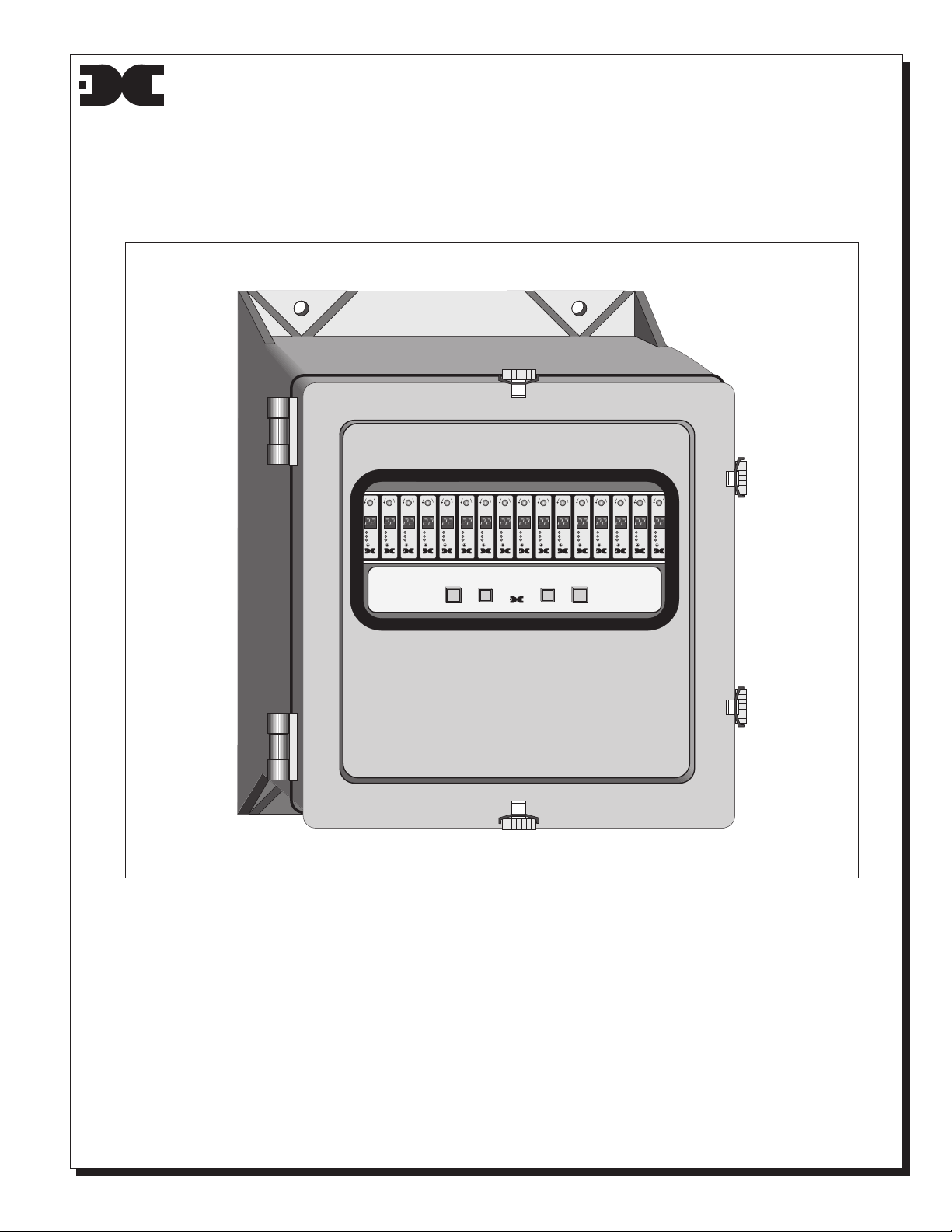
detcon inc.
Detcon Model 1610A-FB
Gas Detection System
Operators Instruction Manual
Document #889, September 14, 1999, Revision 1.0
C
C
C
C
C
C
C
C
C
C
C
C
C
MODEL 10A
H2S MONITOR
HOUSTON, TEXAS
K
K
K
K
K
K
K
K
K
K
O
O
O
O
O
O
O
L
L
L
L
MODEL 10A
H2S MONITOR
HOUSTON, TEXAS
L
MODEL 10A
MODEL 10A
H2S MONITOR
H2S MONITOR
ppm
ppm
ppm
HIGH
HIGH
HIGH
LOW
LOW
LOW
FAULT
FAULT
FAULT
ALARM
ALARM
ALARM
RESET
RESET
RESET
detcon inc.
detcon inc.
detcon inc.
HOUSTON, TEXAS
HOUSTON, TEXAS
MODEL 10A
H2S MONITOR
ppm
ppm
HIGH
HIGH
LOW
LOW
FAULT
FAULT
ALARM
ALARM
RESET
RESET
detcon inc.
detcon inc.
HOUSTON, TEXAS
POWER
L
L
MODEL 10A
MODEL 10A
MODEL 10A
H2S MONITOR
H2S MONITOR
H2S MONITOR
ppm
ppm
HIGH
HIGH
LOW
LOW
FAULT
FAULT
ALARM
ALARM
RESET
RESET
detcon inc.
detcon inc.
detcon inc.
HOUSTON, TEXAS
HOUSTON, TEXAS
HOUSTON, TEXAS
AMBIENT AIR MONITOR
3AMP 10 AMP
O
L
ppm
HIGH
LOW
FAULT
ALARM
RESET
MODEL 1610AFB
detcon inc.
HOUSTON, TEXAS
MODEL 10A
H2S MONITOR
HOUSTON, TEXAS
K
O
O
O
L
L
L
MODEL 10A
MODEL 10A
H2S MONITOR
H2S MONITOR
ppm
ppm
ppm
HIGH
HIGH
HIGH
LOW
LOW
LOW
FAULT
FAULT
FAULT
ALARM
ALARM
ALARM
RESET
RESET
RESET
detcon inc.
detcon inc.
detcon inc.
HOUSTON, TEXAS
HOUSTON, TEXAS
MODEL 10A
H2S MONITOR
HOUSTON, TEXAS
ALARM
DISABLE
C
K
K
K
O
O
O
MODEL 10A
H2S MONITOR
HOUSTON, TEXAS
O
L
L
L
MODEL 10A
MODEL 10A
H2S MONITOR
H2S MONITOR
ppm
ppm
ppm
HIGH
HIGH
HIGH
LOW
LOW
LOW
FAULT
FAULT
FAULT
ALARM
ALARM
RESET
RESET
detcon inc.
detcon inc.
detcon inc.
HOUSTON, TEXAS
HOUSTON, TEXAS
L
ppm
HIGH
LOW
FAULT
ALARM
RESET
detcon inc.
C
C
K
K
O
L
MODEL 10A
H2S MONITOR
ppm
HIGH
LOW
FAULT
ALARM
ALARM
RESET
RESET
detcon inc.
HOUSTON, TEXAS
❏ 1.0 INTRODUCTION
Detcon Model 1610AFB gas detection system consists of 3 major assemblies:
1. The NEMA 4 fiberglass control enclosure.
2. The single channel digital control modules.
3. The remote mount gas sensor assemblies.
The NEMA 4 fiberglass control enclosure is detailed in section 1.0 of the manual, the
control modules in section 2.0 and applicable sensor assemblies in section 3.0.
Page 2

❏ 1.1 DESCRIPTION
Detcon Model 1610A-FB control enclosure is a
NEMA 4X molded fiberglass case with hinged,
gasketed door and is designed for surface mounting
in both indoor and outdoor locations. An
unbreakable glass view window is mounted in the
door. The NEMA 4X rating is by definition raintight
and therefore suitable for outdoor location in
electrically non-hazardous environments.
The control enclosure houses the mainframe
hardware compatible with Detcon Model Series 10A
digital electronic controls. Model 1610A-FB system
capacity is up to 10 channels consisting of remote
mounted area sensors and single channel electronic
controls (Detcon Model 10A). The system is
powered by AC line power and/or 24 VDC unless
otherwise specified at time of order.
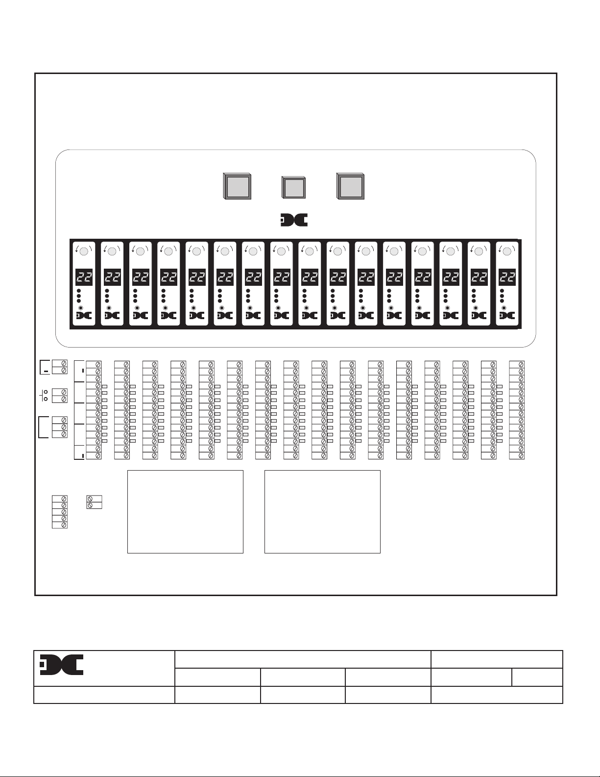
The control enclosure includes, as standard
operating controls (DWG #886.27A); a power on/off
switch, an alarm disable switch and a line power
fuse. Discreet output terminal strips located on the
controller mother board are provided for sensor
terminations, Form C dry contact alarm outputs,
4-20ma outputs for remote recording devices, AC
power in, DC power in, remote reset as well as
relay logic and power terminations for the multiple
alarm relay circuit. Form C relay outputs may be
discreet, zoned or common by gold plated jumper
tabs located on the controller mother board. Form C
dry contacts; common, normally open and normally
closed, are provided for 3 alarms; High, Low and
Fault. Contacts are rated at .6 amp @125 VAC / 2
amp @ 30 VDC. When used in conjunction with the
multiple alarm relay circuit (part #5026), contacts
are rated 8 amp @ 117 VAC / 5 amp @ 30 VDC.
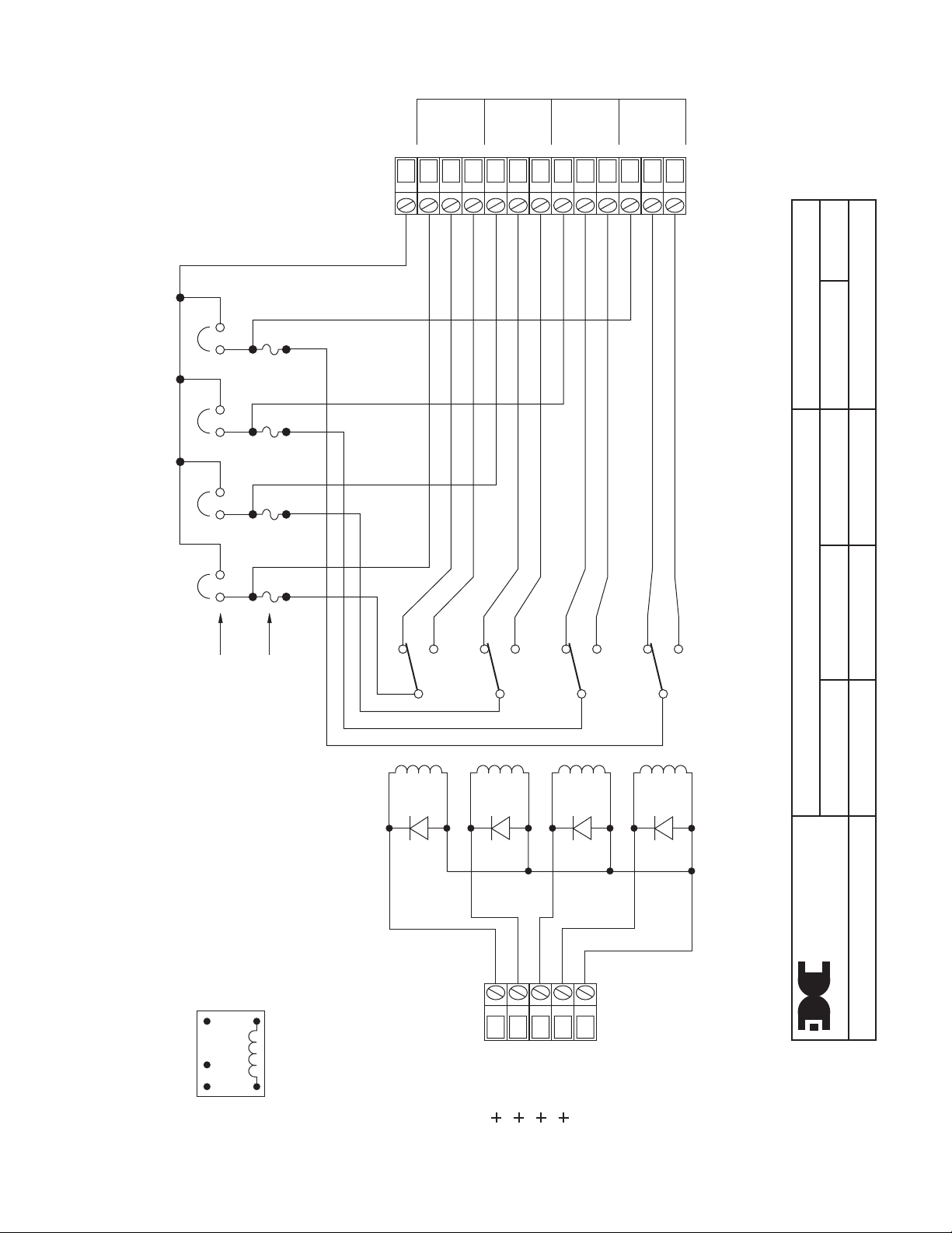
❏ 1.2 MUTIPLE ALARM RELAY CIRCUIT
A multiple alarm relay circuit (DWG #377.01A)
mounted on the controller mother board is provided
with each Detcon Model 1610A-FB. Mounting
provisions for an additional alarm circuit are also
provided. The alarm circuit consists of 4 interposing
relays (contacts are rated 8 amp @ 117 VAC / 5
amp @ 30 VDC) with 24VDC coils as standard.
Other coil voltage ratings must be specified at time
of order. The alarm circuit can be configured to
output Form C dry contacts (common, normally
open and normally closed), AC power or DC power.
A 5 amp microfuse is provided for each relay and
is configured in series with the common pole of its
respective relay. This configuration is functional
regardless of whether Form C dry contacts, AC
power or DC power outputs are used.
An In/Out termination is provided for applying AC
or DC power into any one of the interposing relays.
A gold plated jumper tab is used to apply the in/out
power option to its corresponding relay, thus the 4
relays may be used in a combination of Form C dry
contacts and VDC outputs or Form C contacts and
VAC outputs.
The terminations labled "Alarm Coil Power"
located to the left of the alarm circuit are used only
for coil power. The "+" termination may be used to
provide for various relay logic through the Form C
dry contacts of each individual Model 10A channel
located on the controller mother board directly
above the alarm circuit card. The "-" termination
should be wired into the common termination
(shown by a common symbol) located on the left of
the alarm circuit board.
The terminations labled "Alarm Power" located to
the far left of the unit are used for providing power
to the In/Out termination on the alarm circuit card.
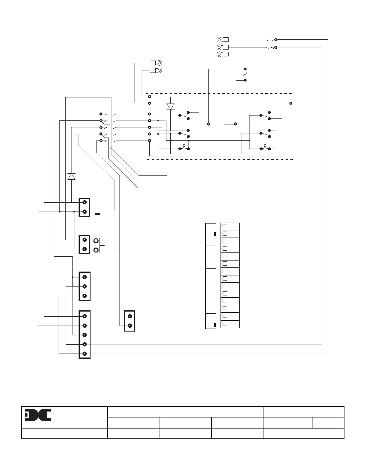
As can be seen in the 1610A-FB schematic / wiring
diagram (DWG #888.01A), the alarm power
terminations for AC come directly from the AC input
terminals located above on the controller mother
board. The same is true of the DC power
terminations. Note: DC power used to drive alarms
must be obtained through a remote DC power
source. The remote DC power source should be
terminated to the terminals labled "DC IN" located
on the controller mother board. The "DC IN"
terminations function as both an alternative DC
source used to power the 1610A-FB as well as
provide power for DC alarms. The 1610A-FB power
supply is not capable of providing power for alarm
devices.
❏ 1.3 ALARM DISABLE
The alarm disable switch, located on the front
panel, operates by removing DC common from the
"Alarm Coil Power" terminals. Disabling of alarms
Detcon Model 1610A-FB Gas Detection System PG.2
does not inhibit any function of the Model 10A
digital control module. The digital display, alarm
LED's and on board alarm relays remain active.
Page 3

❏ 1.4 REMOTE RESET
A remote mounted normally open momentary
switch may be used to reset all Model 10A
controllers. The reset function is effective when
the Model 10A's respective alarms have been
❏ 1.5 INSTALLATION
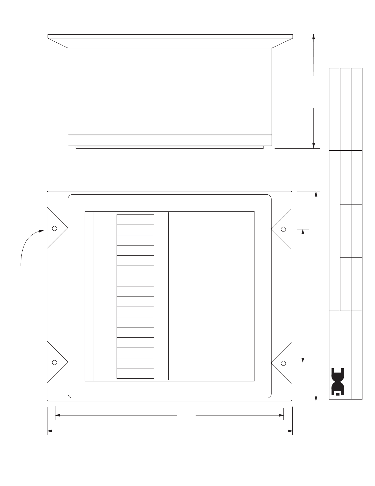
Step 1. Securely mount the 1610A-FB enclosure
in accordance with detail drawing NO. 887.26A.
Step 2. Connect 117 VAC input wiring to the
lugless terminal strip (labled AC IN) on the
controller mother board as detailed in drawing No.
886.27A. Line power current load is maximum 2
amps. (Note: a jumper selectable plug located on
the power supply may be used to allow for 220
VAC input.)
Step 3. Connect the 24 VDC standby battery to
the lugless terminal strip (labled DC IN) on the
controller mother board as detailed in drawing NO.
886.27A. The DC current load is a maximum 3
amps.
Caution: Observe correct polarity when
terminating all input / output field wiring. Failure to
programmed in the latching position and alarm
conditions have passed. Each Model 10A controller
has its own alarm reset switch which is discussed
further in section 2.0.
do so may result in circuit damage on power up.
Step 4. If applicable, connect a normally open
momentary remote mounted switch to the lugless
terminal strip (labeled RESET) located on the
controller mother board as detailed in drawing NO.
886.27A.
Step 4. Refer to installation and wiring detail of
remote mount sensor assemblies as detailed in
section 3.0. Terminate field wiring from sensors to
Model 1610A-FB lugless terminal strips located on
the controller mother board as shown in drawing
NO. 886.27A.
Note: Based on the application and use of relay
contact outputs, complete all wiring terminations
prior to application of power. Shut-in controls may
be omitted until system test is complete.
❏ 1.6 START-UP
Upon completion of all field wiring:
Depress the power switch on the controller
assembly front panel. Note that each Model 10A
controller digital display illuminates. Varying
❏ 1.7 POWER SUPPLY
The power supply on the 1610A-FB may be
changed from 110 VAC to 220 VAC input if
available power should warrant the change. The
procedure does not necessarily require the
removal of the power supply, however, if it is the
first time it is done by a given operator or if the
control enclosure is already wired in (making
removal of the mainframe assembly from the
weatherproof enlosure difficult) it is advisable that
the power supply be removed.
The actual procedure is as simple as moving the
plug selectable wire from the 110V terminal to the
220V terminal located on the power supply printed
circuit board. The wire is labled W1 on the power
supply PCB and the terminals are labled 110V and
220v respectively.
readings may occur during sensor warm-up. A 10
second alarm delay will occur on power up.
Refer to section 3.0 for additional sensor start-up
detail.
(1) Remove the power supply (unless
experienced in the procedure) according to the
instructions listed below.
(2) Remove the wire (W1) from the 110V terminal
and plug it into the 220V terminal.
The 1010A-FB is modularly designed so as to
avoid unnecessary down time in the event of
component failure. In the event of a power supply
failure, the power supply may be removed without
disconnecting field wiring. To remove and replace
the power supply:
(1) Remove the Model 10A control modules.
(2) Remove the 4 screws from the front panel
and expose the power supply.
(3) Disconnect the 5 pin plug on the left of the
power supply.
Detcon Model 1610A-FB Gas Detection System PG.3
Page 4

(4) Disconnect the 2 pin plug on the right of the
power supply.
(5) Remove the 3 screws from the bracket that
holds the power supply to the controller mother
board.
(6) Lift the power supply out of the enclosure
and remove the five wires from the two terminal
strips located on the power supply.
❏ 1.8 WARRANTY
(7) Replace by reversing the above steps.
Note: Be sure to re-connect the wires properly.
Connect AC to the 3 pin terminal strip; Pin 3 =
GROUND, Pin 2 = L1, Pin 1 = L2. Connect DC to
the Stand up terminals (+ is red; - is black); Pin
numbers are screened on the power supply PCB.
Detcon inc., as manufacturer, warrants under
intended normal use each new Model 1610A-FB
control enclosure to be free from defects in
material and workmanship for a period of one year
from the date of shipment to the original purchaser.
All warranties and service policies are FOB the
Detcon Inc. facility located in the Woodlands, Texas.
❏ 1.9 SPARE PARTS
PART # DESCRIPTION
5026 Multiple alarm relay circuit
3622 250 watt, 24 vdc switcher power supply
0224 Gold plated jumper tab
2812 28 vdc lamp for power and disable switch
0295 5 amp micro fuse
0301 4 amp 3AG fuse
3218 Power switch
3218 Disable switch
2806 Green switch cap
2807 Red switch cap
3280 Fuse holder
Mailing address: P.O. Box 8067, The Woodlands, Texas 77387-8067 ❏ Phone: (281) 367-4100 ❏ Fax: (281) 292-2860
Shipping address: 3200 A-1 Research Forest Dr., The Woodlands, TX 77381
Page 5
MODEL 1610A-FB
GND
+DC
COM
GND
+
L1
L2
L1
L2
DC IN
RESET
AC IN
ALARM
LOGIC
C
O
L
MODEL 10A
H2S MONITOR
ppm
HIGH
LOW
FAULT
ALARM
RESET
detcon inc.
HOUSTON, TEXAS
+
MANCNOCNONCCNONCC
SENSOR
FAULTHIGHLOW
+
4-20MA
K
ALARM
COIL
POWER
C
O
L
MODEL 10A
H2S MONITOR
ppm
HIGH
LOW
FAULT
ALARM
RESET
detcon inc.
HOUSTON, TEXAS
+DC
COM
POWER 4 AMP ALARM
HOUSTON TEXAS
C
C
C
ALARM
RESET
C
K
K
O
O
L
L
MODEL 10A
MODEL 10A
H2S MONITOR
H2S MONITOR
ppm
ppm
HIGH
LOW
FAULT
ALARM
RESET
detcon inc.
HOUSTON, TEXAS
detcon inc.
HOUSTON, TEXAS
K
K
O
L
MODEL 10A
H2S MONITOR
ppm
HIGH
LOW
FAULT
ALARM
RESET
detcon inc.
HOUSTON, TEXAS
K
O
L
MODEL 10A
H2S MONITOR
ppm
HIGH
LOW
FAULT
detcon inc.
HOUSTON, TEXAS
O
L
MODEL 10A
H2S MONITOR
ppm
HIGH
LOW
FAULT
ALARM
RESET
detcon inc.
HOUSTON, TEXAS
INTERPOSING
RELAY CARD
HIGH
LOW
FAULT
C
ALARM
RESET
detcon inc.
C
K
K
O
O
L
L
MODEL 10A
MODEL 10A
H2S MONITOR
H2S MONITOR
ppm
ppm
HIGH
HIGH
LOW
LOW
FAULT
FAULT
ALARM
RESET
detcon inc.
HOUSTON, TEXAS
detcon inc.
HOUSTON, TEXAS
OPTIONAL
INTERPOSING
RELAY CARD
C
ALARM
RESET
DISABLE
C
C
C
C
C
C
ALARM
RESET
C
K
K
O
L
MODEL 10A
H2S MONITOR
ppm
HIGH
LOW
FAULT
ALARM
RESET
detcon inc.
HOUSTON, TEXAS
K
K
K
K
K
O
L
MODEL 10A
H2S MONITOR
ppm
HIGH
LOW
FAULT
ALARM
RESET
detcon inc.
HOUSTON, TEXAS
O
L
MODEL 10A
H2S MONITOR
ppm
HIGH
LOW
FAULT
ALARM
RESET
detcon inc.
HOUSTON, TEXAS
O
L
MODEL 10A
H2S MONITOR
ppm
HIGH
LOW
FAULT
ALARM
RESET
detcon inc.
HOUSTON, TEXAS
O
L
MODEL 10A
H2S MONITOR
ppm
HIGH
LOW
FAULT
ALARM
RESET
detcon inc.
HOUSTON, TEXAS
O
L
MODEL 10A
H2S MONITOR
ppm
HIGH
LOW
FAULT
ALARM
RESET
detcon inc.
HOUSTON, TEXAS
K
O
L
MODEL 10A
H2S MONITOR
ppm
HIGH
LOW
FAULT
detcon inc.
HOUSTON, TEXAS
detcon inc.
MATERIAL
TITLE
DRN BY
FINISH
1610AFB CONTROLLER TERMINALS
TED S.
SCALE
SHEET OF
APPROVED BY
STOCK #
DRAWING NUMBER
DATE
7-18-91
STATUS
886.27A
REV #
0
Page 6
10.25
887.26A
8-4-97
14
DRAWING NUMBER
TITLE
20.25
1610A-FB DIMENSIONS / MOUNTING DETAIL
REFERENCE
DATE
APPROVED BY
SCALE
SHEET OF
0
TED S.
DRN BY
REVISION
MOUNTING HOLE - .44 DIA.
23.07
21.81
detcon inc.
MATERIAL
Page 7
#4
IN / OUT
COM
N.C.
N.O.
#3
COM
N.C.
N.O.
#2
COM
N.C.
N.O.
#1
COM
N.C.
N.O.
39-6-89
REV #
377.01A
#4 #3 #2 #1
I/O JUMPERS
5 AMP MICRO FUSE
#4
#3
#2
#1
DRAWING NUMBER
TITLE
STATUS
DATE
STOCK #
APPROVED BY
SCALE
SHEET OF
TED S.
MULTIPLE ALARM RELAY CIRCUIT
DRN BY
FINISH
5026
detcon inc.
MATERIAL
32 1
TOP VIEW RELAY
NO NC C
45
COIL #4
COIL #3
COIL #2
COIL #1
COMMON
Page 8
16 GA.-BLK-9"
16 GA.-RED-9"
TO PS COM
TO PS +
TO PS GND
TO PS L2
TO PS L1
16 GA.-GRN
16 GA.-WHT
16 GA.-BLK
16 GA.-BLK
2 AMP
16 GA.-BLK
COMMON
+OUT
DISABLE
DC IN
RESET
AC IN
L1
+IN
+
L1
L2
GND
+DC
COM
L1
L2
GND
16 GA.-BLK
16 GA.-BLK
16 GA.-RED
16 GA.-RED
16 GA.-BLK
ALARM
COIL
POWER
+DC
COM
ALARM
POWER
SWITCH PCB
COMMON BUS
RESET BUS
+ POWER BUS
DISABLE
TYP. MODEL 10A CONTROLLER TERMINALS
+
MANCNOCNONCCNONCC
SENSOR
FAULTHIGHLOW
+
4-20MA
detcon inc.
MATERIAL
ALARM
POWER
TITLE
DRN BY
FINISH
1610AFB WIRING DIAGRAM
SCALE
TED S.
SHEET OF
APPROVED BY
STOCK #
DRAWING NUMBER
DATE
7-18-91
STATUS
888.01A
REV #
0
 Loading...