

Design Dynamics VTD-18NV-JHB, VTD-24NV-JHB, VTD-18PV-JHB, VTD-30NV-JHB, VTD-30PV-JHB Owner's Operation And Installation Manual
Page 1
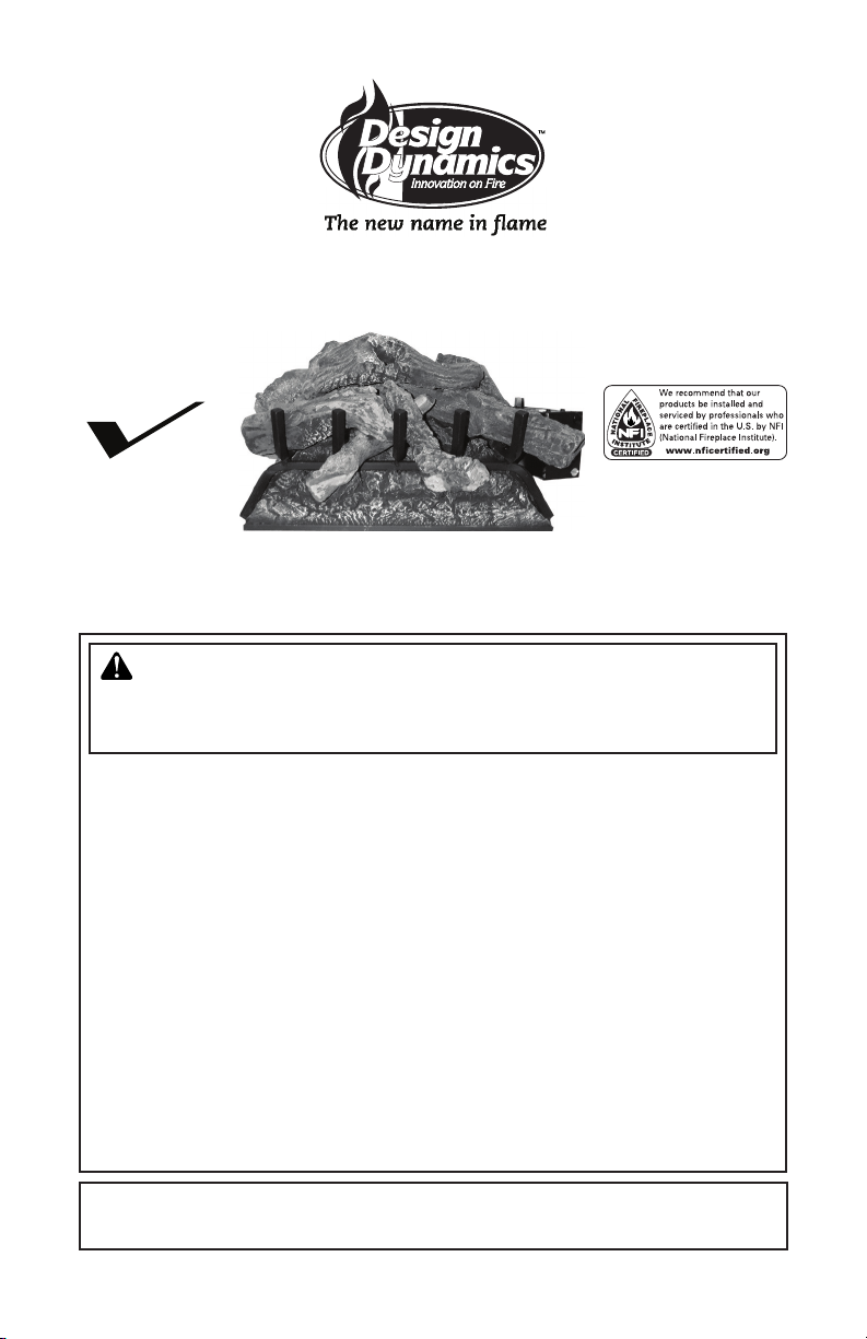
VENTED DECORATIVE APPLIANCE
PFS
US
OWNER’S OPERATION AND INSTALLATION MANUAL
®
MODELS VTD-18NV-JHB, VTD-18PV-JHB, VTD-24NV-JHB,
VTD-24PV-JHB, VTD-30NV-JHB AND VTD-30PV-JHB
WARNING: If the information in this manual is not
followed exactly, a re or explosion may result causing
property damage, personal injury or loss of life.
— Do not store or use gasoline or other ammable
vapors and liquids in the vicinity of this or any other
appliance.
— WHAT TO DO IF YOU SMELL GAS
• Do not try to light any appliance.
• Do not touch any electrical switch; do not use any
phone in your building.
• Immediately call your gas supplier from a neighbor’s
phone. Follow the gas supplier’s instructions.
• If you cannot reach your gas supplier, call the re
department.
— Installation and service must be performed by a quali-
ed installer, service agency or the gas supplier.
INSTALLER: Leave this manual with the appliance
CONSUMER: Retain this manual for future reference.
For more information, visit www.fmiproducts.com
Page 2
TABLE OF CONTENTS
Safety .................................................................. 2
Product Identication ........................................... 4
Local Codes......................................................... 5
Unpacking............................................................ 5
Product Features ................................................. 5
Optional Accessories ........................................... 5
Installation ........................................................... 5
Operation ........................................................... 10
Inspecting Burners............................................. 12
Cleaning and Maintenance ................................ 12
SAFETY
Troubleshooting ................................................. 13
Specications .................................................... 17
Wiring Diagrams ................................................ 18
Service Hints ..................................................... 18
Technical Service............................................... 18
Replacement Parts ............................................ 19
Accessories ....................................................... 19
Parts .................................................................. 20
Warranty ..............................................Back Cover
WARNING: Improper instal-
lation, adjustment, alteration,
service or maintenance can
cause injury or property damage.
Refer to this manual for correct
installation and operational
procedures. For assistance or
additional information consult a
qualied installer, service agency
or the gas supplier.
This appliance may be installed
in an aftermarket,* permanently
located, manufactured (mobile)
home, where not prohibited by
local codes.
This appliance is only for use
with the type of gas indicated on
the rating plate. This appliance
is not convertible for use with
other gases.
* Aftermarket: Completion of sale, not for
purpose of resale, from the manufacturer.
WARNING: This appliance
is for installation only in a
solid-fuel burning masonry or
UL127 factory-built replace,
constructed of noncombustible
material and connected to a
working ue. (See page 6 for
minimum ue opening.)
WARNING: This is a gas-red
heater. It uses air (oxygen) from
the room in which it is installed.
Provisions for adequate combustion and ventilation air must be
provided. Refer to the National
Fuel Gas Codes, ANSI Z233.1/
NFPA 54, Air for Combustion and
Ventilation.
State of Massachusetts: The
installation must be made by
a licensed plumber or gas
tter in the Commonwealth of
Massachusetts.
WARNING: This product contains and/or generates chemicals
known to the State of California
to cause cancer or birth defects
or other reproductive harm.
WARNING: Keep ue open
when operating unit.
IMPORTANT: Read this owner’s
manual carefully and completely
before trying to assemble, operate or service this log set.
Improper use of this log set can
cause serious injury or death
from burns, fire, explosion,
electrical shock and carbon
monoxide poisoning.
www.fmiproducts.com
114370-02H2
Page 3
SAFETY
Continued
DANGER: Carbon monoxide
poisoning may lead to death!
Carbon Monoxide Poisoning: Early signs
of carbon monoxide poisoning resemble the
u, with headaches, dizziness or nausea. If
you have these signs, the log set may not
be working properly. Get fresh air at once!
Have log set serviced. Some people are
more affected by carbon monoxide than oth-
ers. These include pregnant women, people
with heart or lung disease or anemia, those
under the inuence of alcohol and those at
high altitudes.
Natural and Propane/LP Gas: Natural and
propane/LP gas are odorless. An odor-making
agent is added to the gas. The odor helps you
detect a gas leak. However, the odor added to
the gas can fade. Gas may be present even
though no odor exists.
Make certain you read and understand all
warnings. Keep this manual for reference. It
is your guide to safe and proper operation of
this log set.
WARNING: Any change to
this log set or its controls can
be dangerous.
Do not place clothing or other
ammable material on or near
the appliance. Never place any
objects on the heater.
Appliance base assembly becomes very hot when running.
Keep children and adults away
from hot surface to avoid burns
or clothing ignition. Log set
will remain hot for a time after
shutdown. Allow surface to cool
before touching.
Carefully supervise young chil-
dren when they are in the room
with log set. When using handheld remote accessory keep selector switch in the OFF position
to prevent children from turning
on burners with remote.
You must operate this log set
with a replace screen in place.
Make sure replace screen is
closed before running log set.
WARNING: Do not use a blower insert, heat exchanger insert or
other accessory not approved for
use with this appliance.
WARNING: This appliance is
equipped for use with type of gas
indicated on rating plate.
Keep the log set area clear and
free from combustible materials,
gasoline and other ammable
vapors and liquids.
Children and adults should be
alerted to the hazard of high
temperature and should stay
away to avoid burns or clothing
WARNING: Do not allow fans
to blow directly into the replace.
Avoid any drafts that alter burner
ame patterns.
ignition.
1. Do not place propane/LP supply tank(s)
inside any structure. Locate propane/
LP supply tank(s) outdoors (propane/LP
units only).
Due to high temperatures, the
appliance should be located out
of trafc and away from furniture
and draperies.
114370-02H 3
www.fmiproducts.com
Page 4
SAFETY
Continued
2. If you smell gas
• shut off gas supply
• do not try to light any appliance
• do not touch any electrical switch; do not
use any phone in your building
• immediately call your gas supplier from
a neighbor’s phone. Follow the gas sup-
plier’s instructions
• if you cannot reach your gas supplier,
call the re department
3. Never install the log set
• in a recreational vehicle
• where curtains, furniture, clothing or other
ammable objects are less than 42" from
the front, top or sides of the log set.
• in high trafc areas
• in windy or drafty areas
4. Before installing in a solid fuel burning replace, the chimney ue and rebox must
be cleaned of soot, creosote, ashes and
loose paint by a qualied chimney cleaner.
Creosote will ignite if highly heated. Inspect
chimney ue for damage. If damaged,
repair ue before operating appliance.
5. Do not operate heater if any log is broken.
Do not operate heater if a log is chipped
(dime-sized or larger).
6. This log set is designed to be smokeless.
If logs ever appear to smoke, turn off appliance and call a qualied service person.
Note: During initial operation, slight smok-
ing could occur due to log curing and
the burning of manufacturing residues.
You may wish to add more ventilation by
opening a window.
7. To reduce the creation of soot, follow the
instructions in Cleaning and Maintenance,
page 13.
8. The installation and provisions for combustion and ventilation air must conform
with the National Fuel Gas Codes, ANSI
Z233.1/NFPA 54, Air for Combustion and
Ventilation.
9. To prevent performance problems, do not
use propane/LP fuel tank of less than 100
lb. capacity (propane/LP units only).
10. Do not run log set
• where ammable liquids or vapors are
used or stored
• under dusty conditions
11. Do not burn solid fuel in the replace after
installing the log set. Do not use this log
set to cook food or burn paper or other
objects.
12. Do not use heater if any part has been ex-
posed to or under water. Immediately call
a qualied service technician to inspect
the room heater and to replace any part
of the control system and any gas control
which has been under water.
13. Turn log set off and let cool before servic-
ing, installing or repairing. Only a qualied
service person should install, service or
repair log set.
14. Provide adequate clearances around air
openings.
15. This vented gas log set may not be installed in a bedroom or bathroom in the
Commonwealth of Massachusetts.
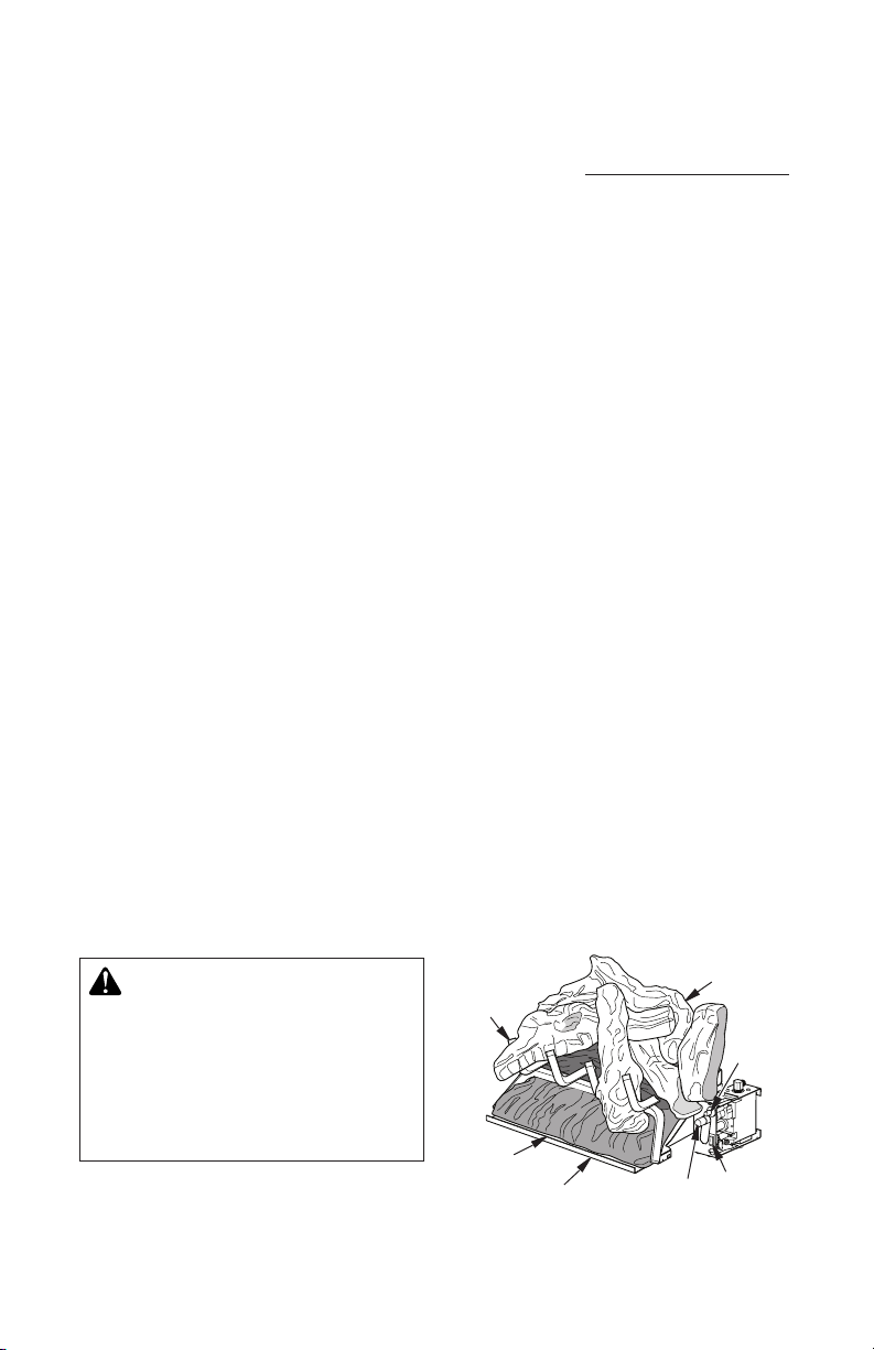
PRODUCT IDENTIFICATION
WARNING: Failure to position the parts in accordance
with these diagrams or failure
to use only parts specically
approved with this appliance
may result in property damage
or personal injury.
www.fmiproducts.com
Grate
Ceramic
Burner
Chassis
Assembly
Figure 1 - Product Identication
Control
Knob
Log Set
Assembly
Piezo
Ignitor
ON/OFF
Switch
114370-02H4
Page 5

LOCAL CODES
Install and use log set with care. Follow all local
codes. In the absence of local codes, use the
latest edition of the National Fuel Gas Code
ANSI Z223.1/NFPA 54*
*Available from:
American National Standards Institute, Inc.
1430 Broadway
New York, NY 10018
National Fire Protection Association, Inc.
Battery march park
Quincy, MA 02269
UNPACKING
CAUTION: Do not remove the
data plates from the grate assembly. The data plates contain
important warranty and safety
information.
1. Remove log set assembly from carton.
Note: Do not pick up assembly by logs.
This could damage unit. Always handle
assembly by grate.
2. Remove control cover oor media components.
3. Remove all protective packaging applied to
log set for shipment.
4. Check heater for any shipping damage. If
heater is damaged call FMI PRODUCTS,
LLC at 1-866-328-4537 for replacement
parts before returning to dealer.
PRODUCT FEATURES
This unitized log set is tested and approved
to ANSI Z21.60 and CSA 2.26 as a vented
decorative appliance.
PIEZO IGNITOR
This unit has a piezo ignitor. This system requires no matches, batteries or other sources
to light appliance.
INSTALLATION
WARNING: Before installing
in a solid fuel burning replace,
the chimney ue and rebox
must be cleaned of soot, creosote, ashes and loose paint by
a qualified chimney cleaner.
Creosote will ignite if highly
heated. A dirty chimney ue may
create and distribute soot within
the house. Inspect chimney ue
for damage. If damaged, repair
ue damper before operating
appliance.
WARNING: Make sure selec-
tor switch is in the OFF position
before installing appliance.
OPTIONAL ACCESSORIES
• VTD-HLCN/P - Converts valve from ON/
OFF to HI/LO
• OFSM-RCN/P - Converts valve from ON/
OFF to HI/LO for use with hand-held ON/
OFF remote (included)
• OF-RC - Converts ON/OFF valve for use
with hand-held ON/OFF remote
See Accessories, page 19.
NOTICE: Installation, service and
repair of this appliance must be
performed by a qualied installer,
service agency, company or gas
supplier experienced with this
type of gas appliance. Only factory
authorized components listed in
these instructions may be used
in accordance with the manufacturer's instructions and all codes
and requirements of the authority
having jurisdiction. Any modica-
tions to or use of unauthorized
components or accessory items
will void the manufacturer’s war-
ranty and may result in a hazard-
ous condition.
114370-02H 5
www.fmiproducts.com
Page 6

INSTALLATION
Continued
WARNING: Do not place lava
rocks and log scraps on burner.
CHECK GAS TYPE
Use the correct gas type (natural or propane/
LP) for your unit. If your gas supply is not cor-
rect, DO NOT install this into your replace.
See the dealer where you bought the appli-
ance for proper type.
WARNING: This appliance is
equipped for either natural gas
or propane/LP gas but not both.
Gas type is indicated on the rating plate. Field conversion is not
permitted.
INSTALLATION AND CLEARANCES
The charts in Figure 2 indicate technical
information regarding the installation of your
gas log set. Please make sure that all of the
specications shown are applicable before
installation is attempted.
MINIMUM FIREBOX SIZES
MODEL
VTD-18NV-JHB
VTD-18PV-JHB
VTD-24NV-JHB
VTD-24PV-JHB
VTD-30NV-JHB
VTD-30PV-JHB
*At depth indicated
LOG
SIZE
INCHES NO. INCHES NO.
29 3/4" 20" 15 1/2" 18"
BURNER ORIFICE
NATURAL PROPANE/LP
18" 0.1495 25 0.0935 42
24" 0.1570 22 0.0980 40
30" 0.1660 19 0.1015 38
SPECIFICATIONS (W.C.)
FUEL INLET PRESSURE
MIN. MAX.
NG 5" 10.5" 3.5
LP 11 " 14" 10
Figure 2 - Technical Information Charts
BACK
WIDTH
FRONT
WIDTH*
DEPTH
28" 16" 14" 18"
36" 27" 18" 18"
MANIFOLD
PRESSURE
HEIGHT
FLUE OPENING SPECIFICATIONS
Note: This vented appliance must be installed
only in a solid-fuel burning replace constructed of noncombustible material. The replace
must include a ue and venting system with
the minimum openings shown in Figure 3.
BTU
MODEL BURNER
VTD-18NV-JHB
VTD-18PV-JHB
VTD-24NV-JHB
VTD-24PV-JHB
VTD-30NV-JHB
VTD-30PV-JHB
18" Ramp 59,000 8" dia.
24" Ramp 69,000 8" dia.
30" Ramp 74,000 8" dia.
INPUT
MIN. VENT
OPENING
Figure 3 - Specications
VENTING SPECIFICATIONS FOR
INSTALLATION
The replace chimney ue and vent must be
drafting properly. To check the vent for proper
drafting: Light a tightly rolled newspaper on
one end and place it at the inside front edge
of the replace. Observe the smoke and be
sure the vent is properly drawing it up the
chimney. If the smoke spills out into the room,
extinguish the ame and remove any obstruc-
tion until proper venting is achieved.
The chimney ue must have a minimum free air
opening of 43" during operation of this log set.
A damper clamp is provided to x the damper
in position.
The minimum ue sizes shown in Figure 2 are
based on a 6' chimney height using round pipe.
Your minimum ue size will vary based on input
rate and chimney height. Refer to the National
Fuel Gas Code ANSI Z223.1/NFPA 54, Section
6.6, for details.
For Massachusetts Residents Only
Installation of this vented gas log set in the
Commonwealth of Massachusetts requires
the damper be permanently removed or
welded in the fully open position.
INSTALLING DAMPER CLAMP
Secure the damper stop clamp to the edge
of the damper as shown in Figure 4, page 7.
If for any reason this clamp doesn't work on
your replace, another suitable clamp or permanent stop must be installed, or the damper
blade must be cut or removed.
www.fmiproducts.com
114370-02H6
Page 7
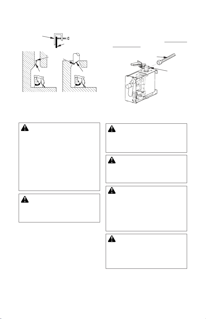
Damper
Clamp
Damper
Clamp
Damper
INSTALLATION
Continued
Damper
Damper
2. Position appliance in replace.
3. Connect to gas supply. See Connecting
To Gas Supply, page 8.
Flexible Gas Hose
(If Allowed by Local Codes)
Gas
Control
Valve
Masonry
Fireplace
Figure 4 - Attaching Damper Clamp
Manufactured
Fireplace
INSTALLING APPLIANCE
ASSEMBLY
WARNING: If installing in a
sunken replace, special care
is needed. You must raise the
replace oor to allow access
to appliance control panel. This
will insure adequate air ow
and guard against sooting and
controls being damaged. Raise
replace oor with noncombustible material. Make sure material
is secure.
CAUTION: Do not pick up appliance assembly by logs. This
could damage unit. Only handle
assembly by grates.
IMPORTANT: Make sure the appliance is level.
If unit is not level, unit will not work properly.
Installation Items Needed• control
cover kit (provided with appliance)
• approved flexible gas hose and fittings
(provided with appliance) (if allowed by local
codes)
• sealant (resistant to propane/LP gas, not
provided)
1. Apply pipe joint sealant lightly to male
threads of gas tting (not provided). Connect approved exible gas hose to inlet
side of gas control valve (see Figure 5).
Figure 5 - Attaching Flexible Gas Hose to
Gas Control Valve
CONNECTING TO GAS SUPPLY
WARNING: This appliance
requires a 3/8" NPT (National
Pipe Thread) inlet connection to
the pressure regulator.
WARNING: A qualied service person must connect heater
to gas supply. Follow all local
codes.
CAUTION: Never connect
propane/LP replace directly to
the propane/LP supply. This unit
requires an external regulator
(not supplied). Install the external regulator between the unit
and propane/LP supply
WARNING: Never connect
natural gas replace to private
(non-utility) gas wells. This gas
is commonly known as wellhead
gas.
114370-02H 7
www.fmiproducts.com
Page 8
INSTALLATION
Continued
Installation Items Needed
Before installing log set, make sure you have
the items listed below.
• external regulator (supplied by installer)
• piping (check local codes)
• sealant (resistant to propane/LP gas)
• equipment shutoff valve *
• test gauge connection *
• sediment trap
• tee joint
• pipe wrench
• approved exible gas line with gas connector (if allowed by local codes) (provided)
* An equipment shutoff valve with 1/8" NPT
tap is an acceptable alternative to test gauge
connection. Purchase the optional equipment
shutoff valve from your dealer.
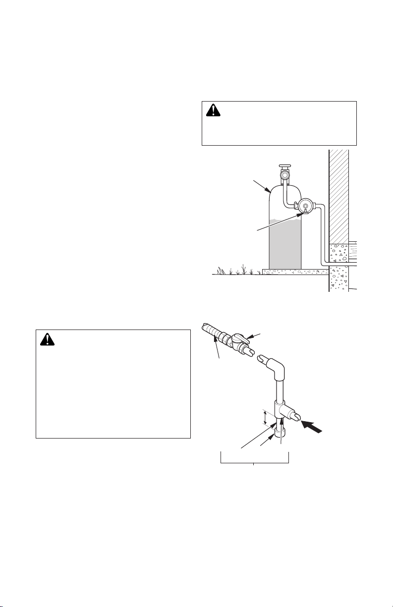
For propane/LP units, the installer must
supply an external regulator. The external
regulator will reduce incoming gas pressure.
You must reduce incoming gas pressure to
between 11" and 14" of water. If you do not
reduce incoming gas pressure, regulator damage could occur. Install external regulator with
the vent pointing down as shown in Figure 6.
Pointing the vent down protects it from freez-
ing rain or sleet.
CAUTION: Use only new,
black iron or steel pipe. Internally-tinned copper tubing may
be used in certain areas. Check
your local codes. Use pipe of
1/2" diameter or greater to allow
proper gas volume to heater. If
pipe is too small, undue loss of
volume will occur.
Installation must include an equipment shutoff
valve, union and plugged 1/8" NPT tap. Locate
NPT tap within reach for test gauge hook up.
NPT tap must be upstream from log set (see
Figure 7).
IMPORTANT: Install equipment shutoff valve
in an accessible location. The equipment
shutoff valve is for turning on or shutting off
the gas to the appliance.
Check your building codes for any special
requirements for locating equipment shutoff
valve to replaces.
Apply pipe joint sealant lightly to male NPT
threads. This will prevent excess sealant from
going into pipe. Excess sealant in pipe could
result in clogged heater valves.
WARNING: Use pipe joint
sealant that is resistant to liquid
petroleum (LP) gas.
Propane/LP
Tank
External
Regulator with
Vent Pointing
Down
Figure 6 - External Regulator with Vent
Approved
Flexible Gas
Hose (If allowed
by local codes)
* Purchase the optional shutoff valve from
your dealer.
** Minimum inlet pressure for purpose of input
adjustment.
Pointing Down
Equipment Shutoff Valve
with 1/8" NPT Tap*
Propane/LP Gas
From External
Regulator (11"
W.C.** to 14" W.C.
3" Min.
Pipe Cap Tee
Nipple Joint
Sediment Trap
Figure 7 - Gas Connection
Natural Gas
From Gas Meter
(5" W.C.** to 10.5"
W.C. Pressure)
www.fmiproducts.com
114370-02H8
Page 9

INSTALLATION
Continued
We recommend that you install a sediment
trap in supply line as shown in Figure 7, page
8. Locate sediment trap where it is within
reach for cleaning. Install in piping system
between fuel supply and appliance. Locate
sediment trap where trapped matter is not
likely to freeze. A sediment trap traps mois-
ture and contaminants. This keeps them from
going into heater controls. If sediment trap is
not installed or is installed wrong, heater may
not run properly.
CAUTION: Avoid damage to
gas control. Hold gas control
with wrench when connecting it
to gas piping and/or ttings.
CHECKING GAS CONNECTIONS
WARNING: Test all gas piping
and connections, internal and
external to unit, for leaks after
installing or servicing. Correct
all leaks at once.
WARNING: Never use an
open ame to check for a leak.
Apply a noncorrosive leak detection uid to all joints. Bubbles
forming show a leak. Correct all
leaks at once.
CAUTION: Make sure exter-
nal regulator has been installed
between propane/LP supply
and appliance. See guidelines
under Connecting to Gas Supply, page 7.
3. Pressurize supply piping system by either
opening propane/LP supply tank valve
for propane/LP gas or opening main gas
valve located on or near gas meter for
natural gas, or using compressed air.
4. Check all joints of gas supply piping system.
Apply noncorrosive leak detection uid to
gas joints. Bubbles forming show a leak.
5. Correct all leaks at once.
6. Reconnect log set and equipment shutoff
valve to gas supply. Check reconnected
ttings for leaks.
Test Pressures Equal To or Less Than
1/2 PSIG (3.5 kPa)
1. Close equipment shutoff valve (see Figure 8).
2. Pressurize supply piping system by either
using compressed air or opening main gas
valve located on or near gas meter.
3. Check all joints from gas meter to equipment shutoff valve for natural gas or
propane/LP supply to equipment shutoff
valve for propane/LP (see Figure 9 or
Figure 10, page 10). Apply noncorrosive
leak detection uid to all joints. Bubbles
forming show a leak.
4. Correct all leaks at once.
Equipment
Shutoff
Valve
Figure 8 - Equipment Shutoff Valve
Propane/LP
Tank
Open
Closed
Equipment
Shutoff Valve
PRESSURE TESTING GAS SUPPLY
PIPING SYSTEM
Test Pressures In Excess Of 1/2 PSIG
(3.5 kPa)
1. Disconnect appliance with its individual
equipment shutoff valve from gas supply
piping system. Pressure in excess of 1/2
psig will damage appliance regulator.
2. Cap off open end of gas pipe where equipment shutoff valve was connected.
114370-02H 9
www.fmiproducts.com
Figure 9 - Checking Gas Joints
(Propane/LP Gas Only)
Page 10

INSTALLATION
Continued
PRESSURE TESTING APPLIANCE GAS
CONNECTIONS
1. Open equipment shutoff valve (see Fig-
ure 8, page 9).
2. Open main gas valve located on or near
gas meter for natural gas or open propane/LP supply tank valve.
3. Make sure control knob of appliance is in
the OFF position.
4. Check all joints from equipment shutoff
valve to gas control (see Figure 9, page
9 or Figure 10). Apply noncorrosive leak
detection uid to all joints. Bubbles forming show a leak.
5. Correct all leaks at once.
6. Light appliance (see Operation, page 11).
Check all other internal joints for leaks.
7. Turn off appliance (see To Turn Off Gas
to Appliance, page 12).
OPERATION
FOR YOUR SAFETY
READ BEFORE LIGHTING
WARNING: Keep ue open
when operating unit.
WARNING: If you do not fol-
low these instructions exactly,
a re or explosion may result
causing property damage, personal injury or loss of life.
A. This appliance has a pilot which must
be lighted by hand. When lighting the pilot, follow these instructions exactly.
B. BEFORE LIGHTING smell all around
the appliance area for gas. Be sure to
smell next to the oor because some
gas is heavier than air and will settle
on the oor.
WHAT TO DO IF YOU SMELL GAS
• Do not try to light any appliance.
• Do not touch any electric switch; do
not use any phone in your building.
• Immediately call your gas supplier
from a neighbor’s phone. Follow the
gas supplier’s instructions.
• If you cannot reach your gas supplier,
call the re department.
www.fmiproducts.com
Equipment
Shutoff Valve
Gas Meter
Control Valve
Location
Figure 10 - Checking Gas Joints
(Natural Gas Only)
C. Use only your hand to push in or turn
the gas control knob. Never use tools.
If the knob will not push in or turn by
hand, don’t try to repair it, call a qualied service technician or gas supplier.
Force or attempted repair may result in
a re or explosion.
D. Do not use this appliance if any part
has been under water. Immediately call
a qualied service technician to inspect
the appliance and to replace any part of
the control system and any gas control
which has been under water.
LIGHTING
INSTRUCTIONS
NOTICE: During initial operation of new appliance, metallic
components may emit an odor as
paint and assembly compounds
are heated and cure. Be sure
to provide adequate fresh air if
odors are detected.
WARNING: Damper handle
will be hot if appliance has been
running.
114370-02H10
Page 11

OPERATION
Continued
CAUTION: A mild gas ash
may occur within 10 seconds of
normal shutdown of this appliance. Remain clear of the hearth
area for the entire shutdown process to avoid possible injury.
1. STOP! Read the safety information on
page 10.
2. Make sure equipment shutoff valve is fully
open.
3. Set selector switch in the OFF position.
4. Press in and turn control knob clockwise to the OFF position (see
Figure 11).
WARNING: Burners will
come on automatically within
one minute when the selector
switch is in the ON position after
the pilot is lit.
5. Wait ve (5) minutes to clear out any gas.
Then smell for gas, including near the
oor. If you smell gas, STOP! Follow “B”
in the safety information, page 10. If you
don’t smell gas, go to the next step.
6. Press in and turn control knob counter-
clockwise to the PILOT position.
Press in control knob for ve (5) seconds
(see Figure 11).
Note: You may be running this appliance for
the rst time after hooking up to gas supply. If so, the control knob may need to be
pressed in for 30 seconds or more. This will
allow air to bleed from the gas system.
Control Knob
Ignitor
7. With control knob pressed in, press and
release ignitor button. This will light pilot.
If needed, keep pressing ignitor button
until pilot lights.
Note: If pilot does not stay lit, contact a
qualied service person or gas supplier for
repairs. Until repairs are made, light pilot
with match. To light pilot with match, see
Manual Lighting Procedure, page 12.
8. Keep control knob pressed in for 30 seconds after lighting pilot. After 30 seconds,
release control knob.
• If control knob does not pop out when
released, contact a qualified service
person or gas supplier for repairs.
Note: If pilot goes out, repeat steps 4
through 8.
9. Slightly push in and turn control knob coun-
terclockwise to the ON position.
10. Wait one minute and switch selector
switch to the ON position to light burners.
Note: AUTO is not functional.
11. Set ame adjustment knob to any level
between HI and LO. Optional conversion
kit only.
Note: Unit is shipped from the factory with
preset ame and manual on/off switch
only (see Accessories on page 19 for
complete list of accessories and conversion kits).
12. To leave pilot lit and shut off burners only:
turn control knob clockwise to the
PILOT position, or use remote control
manual OFF button, or set selector switch
in the OFF position.
CAUTION: Do not try to ad-
just heating levels by using the
equipment shutoff valve.
WARNING: Make sure the
selector switch is in the OFF
ON/OFF
Switch
position when you are away
from home for long periods of
time. Appliance will come on au-
tomatically with selector switch
in the ON position.
Figure 11 - Control Knob and Ignitor Button
114370-02H 11
www.fmiproducts.com
Page 12

OPERATION
Continued
TO TURN OFF GAS
TO APPLIANCE
1. Turn control knob clockwise to
the OFF position.
2a. Set selector switch in the OFF position.
2b. If Using Optional Hand-Held Remote: Set
selector switch in the OFF position to
prevent draining battery.
3. Close equipment shutoff valve (see Figure
8, page 9).
MANUAL LIGHTING
PROCEDURE
1. Follow steps 1 through 6 under Lighting
Instructions, page 10.
2. Depress control knob and light pilot with
match.
3. Keep control knob pressed in for 30 seconds after lighting pilot. After 30 seconds,
release control knob. Now follow steps 9
through 11 under Lighting Instructions,
page 10.
INSPECTING BURNERS
BURNER FLAME PATTERN
Check ame pattern often. Figure 12 shows
correct burner ame pattern.
NOTICE: Do not mistake orange
ames with yellow tipping. Dirt
or other ne particles are burned
by appliance, causing brief
patches of orange ame.
If burner ame pattern is incorrect, as shown
in Figure 13
• turn appliance off (see To Turn Off Gas
to Appliance, page 12
• see Troubleshooting, page 13
Figure 12 - Correct Burner Flame Pattern
Yellow
Tipping
CLEANING AND
MAINTENANCE
WARNING: Turn off heater
and let cool before cleaning.
CAUTION: You must keep
control areas, burner and circulating air passageways of
replace clean. Inspect these
areas of replace before each
use. Have replace and chimney
inspected yearly by a qualied
service person. Fireplace may
need more frequent cleaning due
to excessive lint from carpeting,
bedding material, pet hair, etc.
Figure 13 - Incorrect Burner Flame
Pattern
www.fmiproducts.com
114370-02H12
Page 13

TROUBLESHOOTING
WARNING: Turn off log set and let cool before servicing. Only a
qualied service person should service and repair log set.
CAUTION: Never use a wire, needle, or similar object to clean
ODS/pilot. This can damage ODS/pilot unit.
Note: All troubleshooting items are listed in order of operation.
OBSERVED PROBLEM
When ignitor button is pressed,
there is no spark at pilot
When ignitor button is pressed,
there is spark at pilot but no
ignition
POSSIBLE CAUSE REMEDY
1. Ignitor electrode not connected to ignitor cable
2. Ignitor cable pinched or
wet
3. Piezo ignitor nut is loose
4. Broken ignitor cable
5. Bad piezo ignitor
6. Ignitor electrode posi-
tioned wrong or broken
1. Gas supply turned off or
equipment shutoff valve
closed
2. Control knob not in PILOT
position
3. Control knob not pressed
in while in PILOT position
4. Air in gas lines when in-
stalled
5. Depleted gas supply (propane/LP only)
6. Pilot is clogged
7. Gas regulator setting is
not correct
1. Reconnect ignitor cable
2. Free ignitor cable if pinched
by any metal or tubing.
Keep ignitor cable dry
3. Tighten nut holding piezo
ignitor to base panel of log
set. Nut is located behind
base panel
4. Replace ignitor cable
5. Replace piezo ignitor
6. Replace ignitor electrode
1. Turn on gas supply or open
equipment shutoff valve
2. Turn control knob to PILOT
position
3. Press in control knob while
in PILOT position
4. Continue holding down
control knob. Repeat igniting operation until air is
removed
5. Contact local propane/LP
gas company
6. Clean pilot (see Cleaning
and Maintenance, page 12)
or replace pilot assembly
7. Replace gas regulator
114370-02H 13
www.fmiproducts.com
Page 14

OBSERVED PROBLEM
Pilot lights but ame goes
out when control knob is
released
TROUBLESHOOTING
Continued
POSSIBLE CAUSE REMEDY
1. Control knob not fully
pressed in
2. Control knob not pressed
in long enough
3. Safety interlock system
has been triggered
4. Equipment shutoff valve
not fully open
5. Pilot flame not touch-
ing thermocouple, which
allows thermocouple to
cool, causing pilot ame to
go out. This problem could
be caused by one or both
of the following:
A) Low gas pressure
B) Dirty or partially clogged
pilot
6. Thermocouple connection
loose at control valve
7. Thermocouple damaged
8. Control valve damaged
1. Press in control knob fully
2. After pilot lights, keep con-
3. Wait one minute for safety
4. Fully open equipment shut-
5. A) Contact local natural or
B) Clean pilot (see Clean-
6. Hand tighten until snug,
7. Replace pilot assembly
8. Replace control valve
trol knob pressed in 30
seconds
interlock system to reset.
Repeat ignition operation
off valve
propane/LP gas company
ing and Maintenance,
page 12) or replace pilot
assembly
then tighten 1/4 turn more
One or both burner does not
light after ODS/pilot is lit
Delayed ignition of burner
Burner backfiring during
combustion
1. Inlet gas pressure is too
low
2. Burner orice clogged
3. Mislocated crossover
tube
4. Remote selector in OFF
position
5. Wire disconnected from
gas control
1. Manifold pressure is too
low
2. Burner orice clogged
3. Mislocated crossover
tube
1. Burner orice is clogged
or damaged
2. Damaged burner
3. Gas regulator defective
www.fmiproducts.com
1. Contact local natural or
propane/LP gas company
2. Clean burner (see Cleaning
and Maintenance, page 12)
or replace burner orice
3. Contact qualified service
person
4. Put remote selector in ON
position
5. See Wiring Diagrams,
page 18
1. Contact local natural or
propane/LP gas company
2. Clean burner (see Cleaning
and Maintenance, page 12)
or replace burner orice
3. Contact qualified service
person
1. Clean burner (see Cleaning
and Maintenance, page 12)
or replace burner orice
2. Replace damaged burner
3. Replace gas regulator
114370-02H14
Page 15

OBSERVED PROBLEM
Orange ame in burner during
burner combustion
TROUBLESHOOTING
Continued
POSSIBLE CAUSE REMEDY
1. Not enough air
2. Gas regulator defective
1. Check burner for dirt and
2. Replace gas regulator
debris. If found, clean
burner (see Cleaning and
Maintenance, page 12)
Slight smoke or odor during
initial operation
Appliance produces a whistling noise when burners
are lit
White powder residue forming
within burner box or on adjacent walls or furniture
Remote does not function
Appliance produces a click-
ing/ticking noise just after
burners are lit or shut off
1. Residues from manufacturing processes and logs
curing
1. Turning control knob to HI
position when burners are
cold
2. Air in gas line
3. Air passageways on appliance blocked
4. Dirty or partially clogged
burner orice(s)
1. When heated, vapors
from furniture polish, wax,
carpet cleaners, etc. may
turn into white powder
residue
1. Battery is not installed.
Battery power is low
1. Metal expanding while
heating or contracting
while cooling
1. Problem will stop after a
few hours of operation
1. Turn control knob to LO
position and let warm up
for a minute
2. Operate burners until air is
removed from line. Have
gas line checked by local
natural or propane/LP gas
company
3. Observe minimum installation clearances (see page
6)
4. Clean burners (see Cleaning
and Maintenance, page 12)
or replace burner orice
1. Turn appliance off when
using furniture polish, wax,
carpet cleaners, or similar
products
1. Replace batteries in receiver and remote control
1. This is common with most
appliances. If noise is ex-
cessive, contact qualied
service person
114370-02H 15
www.fmiproducts.com
Page 16

TROUBLESHOOTING
Continued
WARNING: If you smell gas
• Shut off gas supply.
• Do not try to light any appliance.
• Do not touch any electrical switch; do not use any phone in your
building.
• Immediately call your gas supplier from a neighbor’s phone. Follow the gas supplier’s instructions.
• If you cannot reach your gas supplier, call the re department.
IMPORTANT: Operating log set where impurities in air exist may create odors. Cleaning supplies, paint, paint remover, cigarette smoke, cements and glues, new carpet or textiles, etc.,
create fumes. These fumes may mix with combustion air and create odors. These odors will
disappear over time.
OBSERVED PROBLEM
Appliance produces unwanted
odors
POSSIBLE CAUSE
1. Appliance burning vapors
from paint, hair spray,
glues, cleaners, chemicals, new carpet, etc. (See
IMPORTANT statement
above)
2. Low fuel supply (propane/
LP only)
3. Gas leak. See Warn-
ing statement at top of
page
REMEDY
1. Open flue to maximum.
Stop using odor causing
products while appliance
is running
2. Rell supply tank (propane/
LP only)
3. Locate and correct all leaks
(see Checking Gas Con-
nections, page 9)
Appliance shuts off in use
(ODS operates)
Gas odor even when control
knob is in OFF position
Gas odor during combustion
1. Not enough fresh air is
available
2. Low line pressure
3. ODS/pilot is partially
clogged
1. Gas leak. See Warn-
ing statement at top of
page
2. Control valve or gas control defective
1. Foreign matter between
control valve and burner
2. Gas leak. See Warn-
ing statement at top of
page
www.fmiproducts.com
1. Open window and/or door
for ventilation
2. Contact local natural or
propane/LP gas company
3. Clean ODS/pilot (see
Cleaning and Maintenance,
page 12)
1. Locate and correct all leaks
(see Checking Gas Con-
nections, page 9)
2. Replace control valve or
gas control
1. Take apart gas tubing and
remove foreign matter
2. Locate and correct all leaks
(see Checking Gas Con-
nections, page 9)
114370-02H16
Page 17

SPECIFICATIONS
VTD-18NV-JHB
• Rating (Variable): 59,000 Btu/Hr
• Type Gas: Natural
• Ignition: Piezo
• Manifold Pressure: 3.5" W.C.
• Inlet Gas Pressure (in. of water):
Max - 10.5" W.C., Min* - 5.0" W.C.
VTD-24NV-JHB
• Rating (Variable): 69,000 Btu/Hr
• Type Gas: Natural
• Ignition: Piezo
• Manifold Pressure: 3.5" W.C.
• Inlet Gas Pressure (in. of water):
Max - 10.5" W.C., Min* - 5.0" W.C.
VTD-30NV-JHB
• Rating (Variable): 74,000 Btu/Hr
• Type Gas: Natural
• Ignition: Piezo
• Manifold Pressure: 3.5" W.C.
• Inlet Gas Pressure (in. of water):
Max - 10.5" W.C., Min* - 5.0" W.C.
VTD-18PV-JHB
• Rating (Variable): 59,000 Btu/Hr
• Type Gas: Propane/LP
• Ignition: Piezo
• Manifold Pressure: 10" W.C.
• Inlet Gas Pressure (in. of water):
Max - 14" W.C., Min* - 11" W.C.
VTD-24PV-JHB
• Rating (Variable): 69,000 Btu/Hr
• Type Gas: Propane/LP
• Ignition: Piezo
• Manifold Pressure: 10" W.C.
• Inlet Gas Pressure (in. of water):
Max - 14" W.C., Min* - 11" W.C.
VTD-30PV-JHB
• Rating (Variable): 74,000 Btu/Hr
• Type Gas: Propane/LP
• Ignition: Piezo
• Manifold Pressure: 10" W.C.
• Inlet Gas Pressure (in. of water):
Max - 14" W.C., Min* - 11" W.C.
*For purpose of input adjustment
114370-02H 17
www.fmiproducts.com
Page 18

WIRING DIAGRAMS
AUTO
OFF
ON
Thermopile
ON/OFF REMOTE MODELS ONLY
ON/OFF-HI/LO REMOTE MODELS ONLY
SERVICE HINTS
When Gas Pressure is Too Low
• pilot will not stay lit
• burners will have delayed ignition
• heater will not produce specied heat
• (for propane/LP units) propane/LP gas
supply may be low
You may feel your gas pressure is too low. If
so, contact your local propane/LP or natural
gas supplier.
www.fmiproducts.com
TECHNICAL SERVICE
You may have further questions about
installation, operation, or troubleshooting.
If so, contact FMI PRODUCTS, LLC at
1-866-328-4537. When calling please have
your model and serial numbers of your
heater ready.
You can also visit our web site at
www.fmiproducts.com.
114370-02H18
Page 19

REPLACEMENT PARTS
Note: Use only original replacement parts.
This will protect your warranty coverage for
parts replaced under warranty.
Contact authorized dealers of this product.
If they can’t supply original replacement
part(s), call FMI PRODUCTS, LLC at
1-866-328-4537.
ACCESSORIES
Purchase these accessories from your local
dealer. If they can not supply these accessories
call FMI PRODUCTS, LLC at 1-866-328-4537
for information. You can also write to the ad-
dress listed on the back page of this manual.
LAVA ROCK - GA6060
Order when additional rock is desired (1.8 lb.
bag).
DAMPER CLAMP - GA6080
Permanently opens chimney ue damper for
vented operation.
ON/OFF REMOTE CONVERSION KIT
OF-RC
Converts ON/OFF valve for use with hand-
held ON/OFF remote
When calling, have ready:
• your name
• your address
• model and serial numbers of your heater
• how heater was malfunctioning
• purchase date
Usually, we will ask you to return the part to
the factory.
HI/LO CONVERSION KIT
VTD-HLCN (NG), VTD-HLCP (LP)
Converts valve from ON/OFF to HI/LO
ON/OFF - HI/LO REMOTE
CONVERSION KIT - OFSM-RCN (NG)
OFSM-RCP (LP)
Converts valve from ON/OFF to HI/LO for use
with hand-held ON/OFF remote (included)
114370-02H 19
www.fmiproducts.com
Page 20

PARTS
MODELS VTD-18NV-JHB, VTD-24NV-JHB, VTD-30NV-JHB
11
12
12
10
19
1
3
8
12
23
26
27
2
5
12
4
28
20
7
13
9
13
6
5
24
29
13
22
18
14
17
15
16
13
www.fmiproducts.com
21
25
29
114370-02H20
Page 21

PARTS
This list contains replaceable parts used in your heater. When ordering parts, follow the
instructions listed under Replacement Parts on page 19 of this manual.
** Not a eld replaceable part
KEY
NO. PART NO. DESCRIPTION QTY.
1 ** Chassis • • 1
2 ** Grate • • 1
3 112372-07 Venturi/Shutter • • 1
4 112804-03 Bracket • • • • • • 1
5 112804-04 Plate • • • • • • 2
6 112371-09 Orice, NG • 1
7 14325 Elbow 90°, 1/2 FPT x 3/8 FLRE • • • • • • 1
8 112370-01 Gasket • • • • • • 1
9 901232-01 Flexible Gas Line • • • • • • 1
10 112832-01 Ceramic Burner • • 1
11 112833-04 Log Assembly • • 1
12 111800-01 Screw, #10 Self THD 10
13 M11084-26 Screw, 10-16 x 0.380 • • • • • • 8
14 097159-04 Piezo Ignitor • • • • • • 1
15 099998-01 Switch • • • • • • 1
16 103284-02 Wire Harness • • • • • • 1
17 103784-01 ON/OFF Extension Knob • • • • • • 1
18 14512 Valve, MV NG • • • 1
19 112804-05 Valve Bracket • • • • • • 1
20 114395-01 Pilot Bracket • • • • 1
21 116910-01 Brass 3/8 NPT Coupling • • • • • • 1
22 117005-01 Shroud • • • • • • 1
23 117005-02 Face Plate • • • • • • 1
24 14264 Elbow 90°, Brass 3/8M x 3/8 FLRE • • • • • • 1
25 901062-01 Brass Elbow • • • • • • 1
26 901075-01 Screw, PH #8 x 0.25 • • • • • • 2
27 901072-01 Ignitor Electrode • • • • • • 1
28 901073-01 Pilot • • • • • • 1
29 111816-01 Screw, 10-32 x 0.38 • • • • • • 4
114370-02H 21
** Chassis • • 1
** Chassis • • 1
** Grate • • 1
** Grate • • 1
112372-08 Venturi/Shutter • • 1
112372-09 Venturi/Shutter • • 1
24771 Orice, LP • 1
112371-10 Orice, NG • 1
23102 Orice, LP • 1
112371-11 Orice, NG • 1
26209 Orice, LP • 1
112832-02 Ceramic Burner • • 1
112832-03 Ceramic Burner • • 1
112833-05 Log Assembly • • 1
112833-06 Log Assembly • • 1
14513 Valve, MV LP • • • 1
114395-02 Pilot Bracket • • 1
PARTS AVAILABLE - NOT SHOWN
112363-01 Log Scrap Kit #1 • • • • • • 1
112364-01 Log Scrap Kit #2 • • • • • • 1
114371-01 Warning Plate • • • • • • 1
112799-01 Ember Flakes Kit • • • • • • 1
26839 Rock Wool • • • • • • 1
www.fmiproducts.com
VTD-18PV-JHB
VTD-18NV-JHB
VTD-24NV-JHB
VTD-24PV-JHB
VTD-30NV-JHB
VTD-30PV-JHB
Page 22

NOTES
_____________________________________________________
______________________________________________________
______________________________________________________
______________________________________________________
______________________________________________________
______________________________________________________
______________________________________________________
______________________________________________________
______________________________________________________
______________________________________________________
______________________________________________________
______________________________________________________
______________________________________________________
_____________________________________________________
______________________________________________________
______________________________________________________
______________________________________________________
______________________________________________________
______________________________________________________
______________________________________________________
______________________________________________________
______________________________________________________
www.fmiproducts.com
114370-02H22
Page 23

NOTES
_____________________________________________________
______________________________________________________
______________________________________________________
______________________________________________________
______________________________________________________
______________________________________________________
______________________________________________________
______________________________________________________
______________________________________________________
______________________________________________________
______________________________________________________
______________________________________________________
______________________________________________________
_____________________________________________________
______________________________________________________
______________________________________________________
______________________________________________________
______________________________________________________
______________________________________________________
______________________________________________________
______________________________________________________
______________________________________________________
______________________________________________________
______________________________________________________
______________________________________________________
______________________________________________________
_____________________________________________________
______________________________________________________
______________________________________________________
______________________________________________________
______________________________________________________
______________________________________________________
______________________________________________________
______________________________________________________
______________________________________________________
114370-02H 23
www.fmiproducts.com
Page 24

WARRANTY
KEEP THIS WARRANTY
Model (
located on product or identication tag
Serial No. (
located on product or identication tag
Date Purchased __________________________
Keep receipt for warranty verication.
FMI PRODUCTS, LLC LIMITED WARRANTIES
Standard Warranty: FMI PRODUCTS, LLC warrants this new product and any parts thereof to be free
from defects in material and workmanship for a period of four (4) year from the date of rst purchase from
an authorized dealer provided the product has been installed, maintained and operated in accordance with
FMI PRODUCTS, LLC’s warnings and instructions.
For products purchased for commercial, industrial or rental usage, this warranty is limited to 90 days from
the date of rst purchase.
Factory Reconditioned Products
Limited Warranty: FMI PRODUCTS, LLC warrants factory reconditioned products and any parts thereof
to be free from defects in material and workmanship for 30 days from the date of rst purchase from an
authorized dealer provided the product has been installed, maintained and operated in accordance with
FMI PRODUCTS, LLC’s warnings and instructions.
Terms Common to All Warranties
The following terms apply to all of the above warranties:
Always specify model number and serial number when contacting the manufacturer. To make a claim under
this warranty the bill of sale or other proof of purchase must be presented.
This warranty is extended only to the original retail purchaser when purchased from an authorized dealer,
and only when installed by a qualied installer in accordance with all local codes and instructions furnished
with this product.
This warranty covers the cost of part(s) required to restore this product to proper operating condition and
an allowance for labor when provided by a FMI PRODUCTS, LLC Authorized Service Center or a provider
approved by FMI PRODUCTS, LLC. Warranty parts must be obtained through authorized dealers of this
product and/or FMI PRODUCTS, LLC who will provide original factory replacement parts. Failure to use
original factory replacement parts voids this warranty.
Travel, handling, transportation, diagnostic, material, labor and incidental costs associated with warranty
repairs, unless expressly covered by this warranty, are not reimbursable under this warranty and are the
responsibility of the owner.
Excluded from this warranty are products or parts that fail or become damaged due to misuse, accidents,
improper installation, lack of proper maintenance, tampering, or alteration(s).
This is FMI PRODUCTS, LLC’s exclusive warranty, and to the full extent allowed by law; this express warranty excludes any and all other warranties, express or implied, written or verbal and limits the duration of
any and all implied warranties, including warranties of merchantability and tness for a particular purpose to
four (4) year on new products and 30 days on factory reconditioned products from the date of rst purchase.
FMI PRODUCTS, LLC makes no other warranties regarding this product.
FMI PRODUCTS, LLC’s liability is limited to the purchase price of the product, and FMI PRODUCTS, LLC
shall not be liable for any other damages whatsoever under any circumstances including indirect, incidental,
or consequential damages.
Some states do not allow limitations on how long an implied warranty lasts or the exclusion or limitation of
incidental or consequential damages, so the above limitation or exclusion may not apply to you.
This warranty gives you specic legal rights, and you may also have other rights which vary from state to state.
For information about this warranty contact:
New Products
) _____________________________
) __________________________
2701 S. Harbor Blvd.
Santa Ana, CA 92704
1-866-328-4537
www.fmiproducts.com
114370-02
Rev. H
01/11
 Loading...