

Page 1
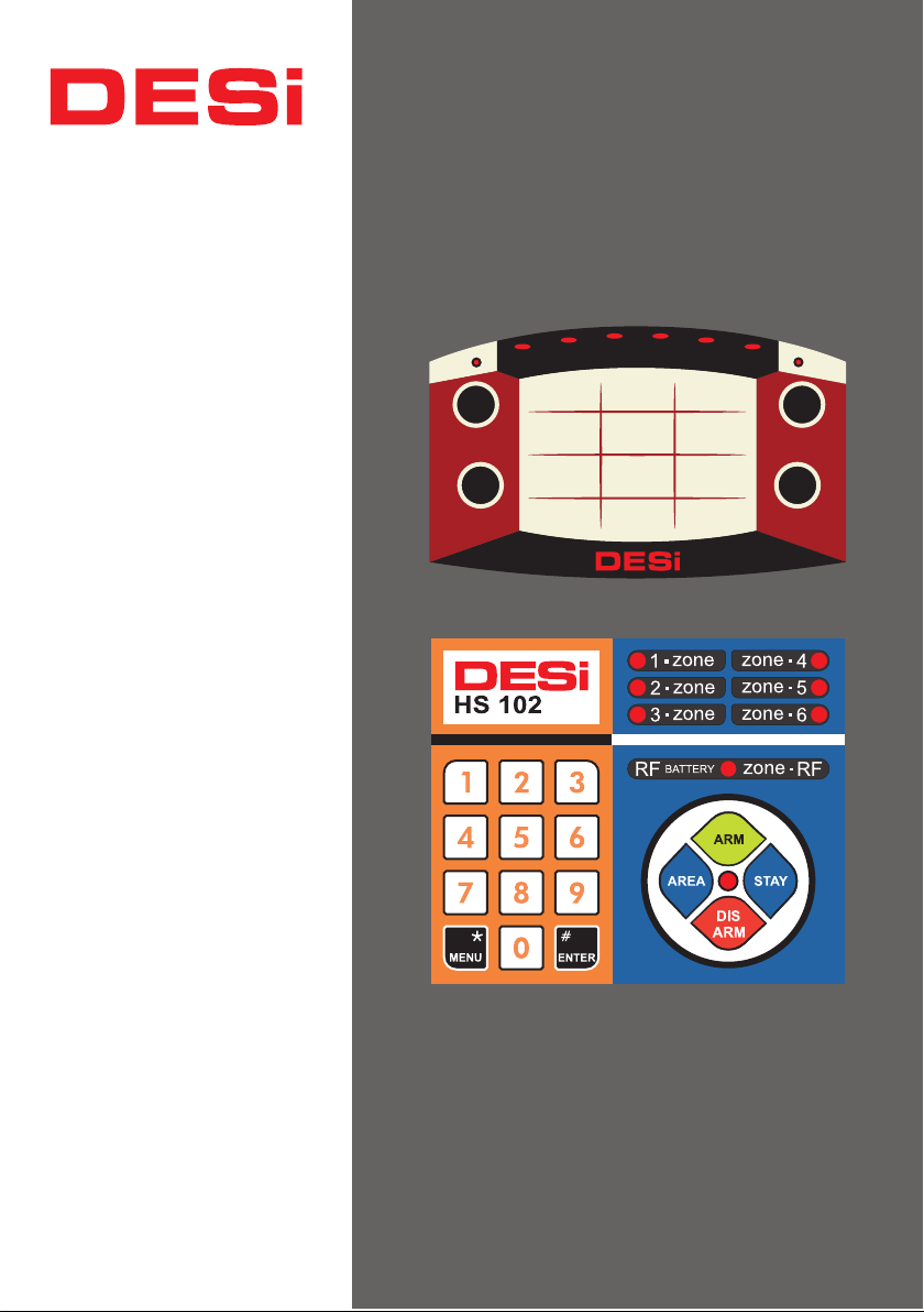
PWR
AREA
3
2
1
1 2 3
4 5
4
5
6
RFI
ARM
6
P R O L I N E
M E T A L I N E
Home&Office Alarm Systems
STAY
7 8 9
MENU
0
ENTER
DIS
ARM
USER
MANUAL
WKS / WTKS / WTGKS
WTKS+ / WTGKS+
Page 2

2
Maintenance/ Energy Efficiency
Product Contents
Box Contents
..................................................................................................................
........................................................................................................................
1. BASIC SYSTEM OPERATIONS
1.1 Arming the Alarm
1.2 Disarming the Alarm
...............
..............
1.3 Special Arming Type-1
1.4 Special Arming Type-2
1.5 Remote Controller
...............................................................................................................
1.5.1 Special Arming Type-1 With Remote Controller
1.5.2 Special Arming Type-2 With Remote Controller
2. FEATURES OF THE DEVICE
2.1. General Features
...................................................................................................................
2.2. Technicial Specifications
3. REPORTING and ADVANCED OPTIONS
3.1. Reporting of Alarm Cause
3.2. Reporting Users .............................................................................................................
3.3. Reporting Total Number Of Enrolled Remote Controllers
3.4. Reporting the Number of Passwords Specified
3.5. Stopping Voice Call Feature At Alarming
3.6. Arming / Disarming Alarm via Remote Access
3.7. Additional Device Control Options via Remote Access
...........................................................................................
..........................................................................................
..............................................................................................
.....
................................................................................................
..........................................................................................................
..........................................................................
...............................................................
...............................
..............................................................
............................................................................................
......................................................................................................
........................................................................
..............................................................................................
............................................
................................................................
.....................................................................
..............................................................
...................................................
3
4
4
5
5
5
5
5
5
5
5
6
6
6
7
7
7
8
8
8
8
8
4. SETTINGS ...........................................................................................................................
4.1. Password Options ............................................................................................................
4.1.1. Administrator Password ................................................................................................
4.1.2. User Passwords .............................................................................................................
4.1.3. Remote Access Password .............................................................................................
4.1.4. Panic Password .............................................................................................................
4.2. Delay Time During Arming .............................................................................................
4.3. Delay Time Before Alarm ...............................................................................................
4.4. Arming / Disarming Tones Level ...................................................................................
4.5. Auto Arming Options .....................................................................................................
4.6. Outdoor Siren ................................................................................................................
4.7. Programmable Relay
4.8. Wireless Detector Tamper Protection
4.9. Adjusting Sound Alerts For Delay Time
4.10. Zone Programming
4.11. One by One Wireless Zone Programming
4.12. Restore Factory Settings
4.13. Enrolling Remote Controller and Wireless Detector
.............................................................................................................
...............................................................................
.............................................................................
............................................................................................................
.........................................................................
.....................................................................................................
.......................................................
9
9
9
9
9
9
9
10
10
10
10
11
11
11
11
12
13
13
Page 3
3
5. VOICE CALLER SETTINGS
5.1. Add / Delete Phone Numbers
5.2. Changing the Voice Message
5.3. Playback Of Recorded Voice Message
5.4. Receiving / Canceling a Dial Tone
5.5. MF / PULSE Call Options
5.6. Secure / Direct Call Selection
5.7. Remote Programming Of Voice Call System
5.8. Restore Factory Settings (
6. ALARM MONITORING CENTER CONNECTION SETUPS
6.1. Enable / Disable Calls to Alarm Monitoring Center
6.2. Entering Subscriber Number to Alarm Monitoring Center
6.3. Entering Phone Numbers to Call for Alarm Monitoring Center
6.4. Forwarding Arming / Disarming Notifications to Alarm Monitoring Center
6.5. Entering Personal Phone Numbers
7. GSM MODULE SETTINGS (
Installation-1
Installation-2
...............................................................................................................................
...............................................................................................................................
.........................................................................................
........
........................................................................
.......................................................................................
.............................................................................
....................................................................................
....................................................................................................
...........................................................................................
..................................................................
for Voice Call Options)
...................................................................................
For GSM connectable models
..........................................................
.............................................
.......................................................
...........................................
...................................
...........................................
)
Maintenance
- You can clean external surfaces by soft, slightly damp cloth.
i
Never use abrasive chemicals or water for this purpose. Be
careful not to change the direction of the detectors during
cleaning and do not damage connections and cables.
- Battery life of the wireless detectors may change depending
on the type of detector and daily usage. DESi recommends
replacing these batteries at least once, every 3 years. You can
get help from DESi dealers.
Energy Efficiency
DESi develops custom designs to reduce energy consumption.
Faulty sensors and improper use of system will give false
alarm signals, that may increase the current consumption. In
order to avoid false alarms, the operating manual should read
in detail and any faulty sensors should be repaired or replaced.
...............
14
14
14
14
15
15
15
15
15
16
16
16
16
16
16
17
18
19
Page 4
4
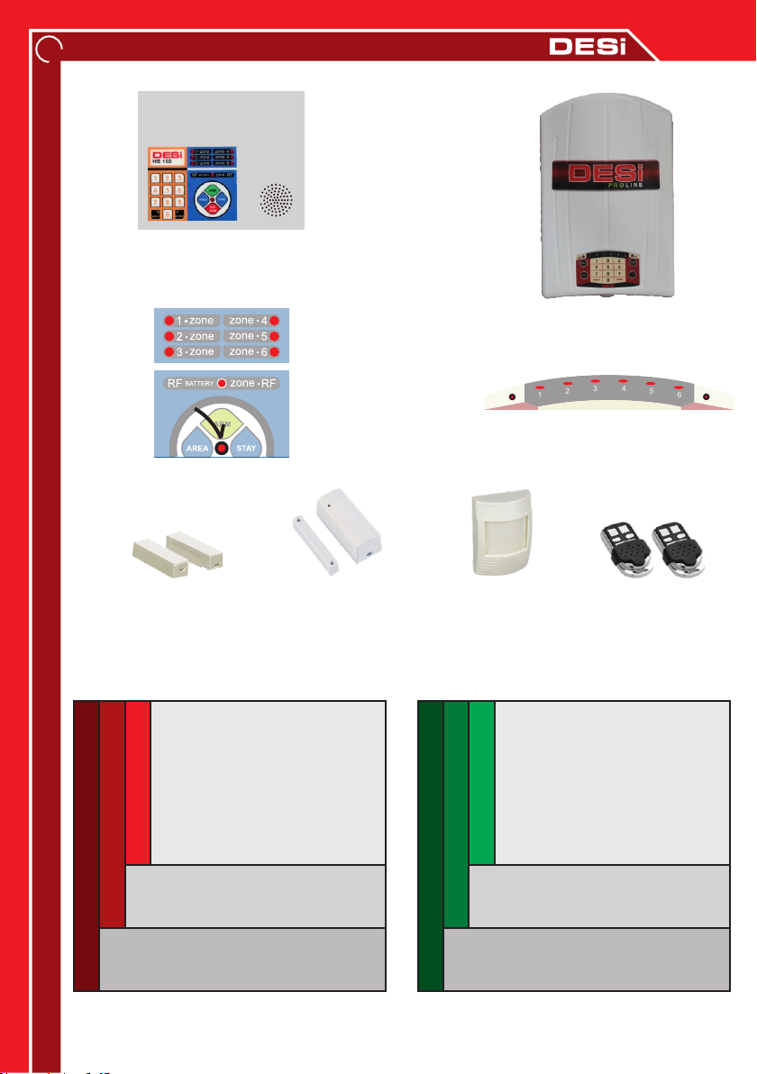
PRODUCT CONTENTS
M E T A L I N E
Control Panel
P R O L I N E
Control Panel
3
4
5
6
RFI
PWR Led
METALINE Indicator LEDs
2
1
PWR
PROLINE Indicator LEDs
Si
E
D
Wired Magnetic
Contact
Wireless
Magnetic Contact
Wired / Wireless
Motion Sensor
Remote
Controller
BOX CONTENTS
M E T A L I N E P R O L I N E
Metal Control Panel
1x Wired Motion Sensor
1x Wired Magnetic Contact
2x Remote Controller
WKS
1x Battery
WTKS
2x Warning Label
WTGKS
Voice Caller
(Landline Connection Available)
WTGKS
Voice Caller
(GSM Connection Available)
The motion detector in WTKS + and WTGKS + is wireless and there is 1 wireless magnetic
contact in the box.
Plastic Control Panel
1x Wired Motion Sensor
1x Wired Magnetic Contact
2x Remote Controller
WKS
1x Battery
WTKS
2x Warning Label
Voice Caller
(Landline Connection Available)
Voice Caller
(GSM Connection Available)
Page 5
- Protect all parts of the system from water and heat.
- Your device has a battery that can operate the system for
!
UYARILAR
approximately 2 days to prevent power failures. It is
recommended to replace this battery once, every 2 years.
- If the PWR LED is blink for 2 times in the standby and you hear
buzzer sounds after arming, that means device is not receiving
power. If you hear this warning tone please check the electrical
connection.
- If there is a fault in your system, please contact DESi authorized
technical services as soon as possible. Do not allow to interfere
your device anyone other than the authorized service. Accident,
breakdown, etc. which may occur due to unauthorized services.
DESI is not responsible for that kind of situations.
- The service time of the product is 7 years.
1. BASIC SYSTEM OPERATIONS
1.1 Arming the Alarm:
Press <MENU> then <ARM>. The alarm will be activated with a long beep and will be active.
1.2 Disarming the Alarm
Enter your 4-digit password and press <DISARM>. (The factory password is 0000.) The alarm
will be disabled after three short beeps.
5
1.3 Special Arming Type-1:
Press <MENU> then <STAY>. The alarm will be activated with a long beep and the alarm will
be activated. (In this type of arming, zone 2 is disabled according to the factory settings.)
1.4 Special Arming Type-2:
Press <MENU> first, then press <STAY> 2 times. The alarm will be activated with a long beep
and the alarm will be activated. (In this type of arming, field 3 is disabled according to the
factory settings.)
1.5 Remote Controller:
Enables the alarm silently. Disarm
Arming
1.5.1 Special Arming Type-1 With Remote Controller:
First press and then
1.5.2 Special Arming Type-2 With Remote Controller:
First
press and then press button 2 times
Disarming
press
the alarm and the phone call if
pressed while the siren is
sounding.
button.
.
Panic
Alarm
Page 6

6
2. FEATURES OF THE DEVICE
2.1. General Features
Ÿ You can use your alarm system with a remote control or password.
Ÿ Your alarm panel can be used with DESi brand wired and wireless detectors.
Ÿ In case of emergency, you can give a panic alarm with remote control.
Ÿ You can set the delay time after you have activated your alarm, and you can set the buzzer
to beep during the startup and standby period.
Ÿ You can increase or decrease the levels of arming or disarming warning sounds, also you can
activate the system silently with the remote control any time.
Ÿ Your device notifies power failures with leds.
Ÿ Your device has a programmable relay output.
Ÿ If you wish, the tamper detection can give an alarm even if the system is disarmed.
Ÿ Your device has a output for a wired smoke detector.
Ÿ Partial Arming: You can disable some of the detectors. Addition to normal arming, the
system offers 2 different partial arming options. (see 4.10 Programming the Zones)
Ÿ 3 Level Delayed Area: When you want to use your system with a password, one or more
detectors can detect while you are going to the keypad to enter the password. In this case,
you can programme your detectors to avoid wrong alarms. (see 4.10 Programming the Zones)
Ÿ 24 Hours Active Area: For fire detectors (or for a different reason), you can have some
areas which need to be in control even when the alarm is disarmed. (see 4.10 Programming
the Zones)
Ÿ Panic Area: You can activate the voice call before the siren rings. (see 4.10 Programming
the Fields)
Ÿ Auto Arming: Your device is equipped with automatic arming option to prevent accidental
disarming or against forgetting to arm. (see 4.5)
Ÿ Reporting: Your device can report the detectors that caused the alarm, the password(user)
disarmed the alarm, or the total number of remote controllers and passwords in the system.
Ÿ Voice Call Features (Except WKS model): Your system has a telephone connection. The
device can call up to 6 different phone numbers and leave a 10-second voice message or it
can be monitored every second by the alarm monitoring center. Also you can arm/disarm or
control the relay output of your device by accessing it remotely.
2.2. Technicial Specifications
Operating Voltage
: 220 V AC
Battery: 12 Volt DC (4 Ah)
Wireless Device Frequency:: 433.92 Mhz
Wireless Zone Count:32
Remote Control Memory: 8
Password Structure
: 1 admin + 7 user + 1
remote access + 1 panic alarm passwords
Wired Zone Count: 6 (
Maximum Number of Wired Detectors
programmable)
: 10 (The
total current consumption cannot exceed 500 mA.)
Other Connection Features: Programmable
relay, smoke detector output, outdoor siren
output, external keypad connection, PSTN
(landline) and GSM caller (depending on the
model.)
Page 7
7
3. REPORTING and ADVANCED OPTIONS
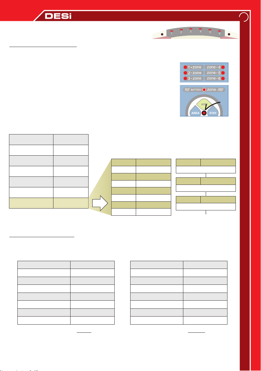
3.1. Reporting of Alarm Cause
When the alarm is disarmed, follow the instructions below to
1
PWR
PROLINE Indicator LEDs
3
2
4
5
6
find out which wired or wireless zone cause the alarm:
[ ADMIN PASSWORD ] → <MENU> → <0> → < 5 >
You could find the cause of the alarm by looking at the indicator of
the device (table below). If the RF.Zone / RFI led is lit, press the
<STAY> button to see which wireless sensor causes an alarm. If you
press <AREA> during reporting, you will see the cause of the
previous alarm. The alarm caused by entering a panic password is not
PWR
Led
reported. System keeps the last 8 alarms in memory.
Cause For Alarm
Wired Zone 1
Wired Zone 2
Wired Zone 3
Wired Zone 4
Wired Zone 5
Wired Zone 6
Wiress Zones
Display
( / )META PRO
1. Zone / 1
2. Zone / 2
3. Zone / 3
4. Zone / 4
5. Zone / 5
6. Zone / 6
RF. Zone / RFI
STAY
RF Zone
Zone 1
Zone 2
Zone 3
Zone 4
Zone 5
Zone 6
Zone 7
Display
( / )META PRO
1. Zone / 1
2. Zone / 2
3. Zone / 3
4. Zone / 4
5. Zone / 5
6. Zone / 6
RF. Zone / RFI
METALINE Indicator LEDs
RF Zone
Zone 9
Zone 17
Zone 25
Display
( / )META PRO
1. Zone / 1
(2 times blink)
1. Zone / 1
(3 times blink)
1. Zone / 1
(4 times blink)
PWR / PWRZone 8
3.2. Reporting Users
If you want to see which user has disarmed the alarm system, follow the instructions below
when the alarm is disarmed:
[ ADMINPASSWORD ] → <MENU> → <0> → < 4 >
Disarmed User
Admin Password
1. User Password
2. User Password
3. User Password
4. User Password
5. User Password
6. User Password
7. User Passwordi
Indicator LEDs SOLID
Display
( / )META PRO
1. Zone / 1
2. Zone / 2
3. Zone / 3
4. Zone / 4
5. Zone / 5
6. Zone / 6
RF. Zone / RFI
PWR / PWR
Disarmed User
1. Remote C.
2. Remote C.
3. Remote C.
4. Remote C.
5. Remote C.
6. Remote C.
7. Remote C.
8. Remote C.
Indicator LEDs BLINKS
Display
( / )META PRO
1. Zone / 1
2. Zone / 2
3. Zone / 3
4. Zone / 4
5. Zone / 5
6. Zone / 6
RF. Zone / RFI
PWR / PWR
RFI
By pressing the <AREA> button, you will see the previous user who has disarmed the device.
Your system keeps the last 8 users in memory. Remote access disarm process will not listed.
Page 8

8
3.3. Reporting Total Number Of Enrolled Remote Controllers
If you want to learn how many remote controller have been enrolled to your system,
follow the instructions below when the alarm is disabled:
[ ADMIN PASSWORD ] → <MENU> → <0> → < 1 >
The number of controls enrolled to the device will be
reported as shown in the table. The device
automatically exits the program after reporting.
The device can recognize maximum 8 remote
controllers.
3.4. Reporting the Number of Passwords:
To learn the number of passwords defined, follow the
instructions below when the alarm is disabled:
[ ADMIN PASSWORD ] → <MENU> → <0> → < 2 >
The number of passwords defined will be reported as
shown in the table above. The device automatically exits
the program after reporting. The device can recognize
Defined Password / Remote Controllers
maximum 8 paswords.
3.5. Stopping Voice Call Feature At Alarming:
-If “ # ” button is pressed, the phone call will be stopped. The system does not call other
phone numbers.
- If “ * ” button pressed, the system will call the next phone number.
-If phone closed without pressing any buttons, system will call other phone numbers and then
call back to main number. (voice call could not stopped by other called numbers)
If you want to stop calls with your remote control, press that button
3.6 Arming / Disarming Alarm via Remote Access
( Voice Call Module Included Models
Only)
Dial the phone number connected to device and ring 5 times. After the fifth ring, the system
automatically answers the call and the buzzer sounds will hear then remote access password
has to entered from the phone key pad. When you hear confirming tone, the alarm will be
armed by pressing the button “1” or by pressing button“0” the alarm wil be disarmed.
3.7. Additional Device Control Options via Remote Access
( Voice Call Module Included
Models Only)
You can control a device like boiler, lighting, etc. connected to your system with an optional
module. The output of the optional module should connect to supply input of the device.
Dial the phone number connected to device and ring 5 times. After the fifth ring, the system
automatically answers the call and the buzzer sounds will hear then remote access
password has to entered from the phone key pad. When you hear confirming tone, the extra
equipment is actived by pressing the button “2” or by pressing button “3” the extra
equipment is deactivated.
Page 9
4. SETTINGS
4.1. Password Options
- You can define 1 administrator, 7 users, 1 remote access and 1
panic password to your system.
!
WARNING
4.1.1. Administrator Password: Administrator password has administrative rights like, defining
user passwords, changing settings, setting zones and reporting. This password also arm/disarm
the system. The factory default administrator password is [0000]. To change this password,
follow the instructions below when the alarm is disarmed:
[ADMIN PASS.] → < MENU> → <5> → <0> → [ NEW PASS.] → <AREA> → [NEW PASS. ] → < AREA>
After this steps, the buzzer will give a warning tone and the administrator password will be
changed.
4.1.2. User Passwords: Passwords that can be used to disarm the device. You can specify up to
7 different user passwords. Follow the instructions below when the alarm is disarmed: Setting
the 1.User Password
[ADMIN PASS.] → <MENU> → <5> → <1> → [NEW PASS.] → <AREA> → [NEW PASS.] → <AREA>
Setting the 5.User Password
[ADMIN PASS.] → <MENU> → <5> → <5> → [NEW PASS.] → <AREA> → [NEW PASS.] → <AREA>
- For your safety please change the factory default password.
- All passwords must be 4 digits.
9
4.1.3. Remote Access Password (Voice Call Module Included Models Only): You can remotely
arm, disarm, and control the extra output of your device by accessing your system via
telephone. To define this password, follow the instructions below when the alarm is disarmed:
[ADMIN PASS.] → <MENU> → <4> → TONE → <MENU> → <9> → [NEW PASS] → <ENTER>
To deactivate the remote access feature, press <ENTER> without entering a new password.
4.1.4. Panic Password: This password is used when malicious people want to disarm the alarm
by threat. If the system has been disarmed with a panic password, it will call the phone
numbers which entered at setup. (silently - without siren louds). This feature only available in
voice caller module included models. To define this password, follow the instructions below
when the alarm is disabled:
[ADMIN PASS.] → <MENU> → <5> → <8> → [NEW PASS.] → <AREA> → [NEW PASS.] → <AREA>
After this steps, the buzzer will give a warning tone and the panic password will be set.
4.2. Delay Time During Arming:
That is time to exit when the alarm is armed. Factory default timing is 15 seconds. If you want
to change this, follow the instructions below when the alarm is disabled:
[ADMIN PASS.] → <MENU> → <8> → <1> → [NEW DELAY TIME - In Seconds] → <STAY>
After this steps, the buzzer will give a warning tone and new delay time will be set.
Page 10
10
4.3. Delay Time Before Alarm
When the system is armed, there is 15-second delay time for disarming the system with
your password. If you want to change the time, follow the instructions below when the
alarm is disarmed:
[ADMIN PASS.] → <MENU> → <8> → <2> → [NEW DELAY TIME - In Seconds] → <STAY>
After this steps, the buzzer will give a warning tone and new delay time will be set.
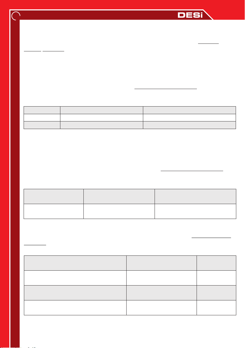
4.4. Arming / Disarming Tones Level
Arming and disarming warning sounds can be set to 3 different levels, low, normal and high.
To adjust the level, follow the instructions below when the alarm is disarmed:
[ADMIN PASS.] → <MENU> → <6> → VIEW THE INDICATOR.
Status Display (META / PRO) Choice
Normal Level
Low Level
High Level
5. Zone / 5 ve PWR /
5. Zone / 5 solid
PWR / PWR solid
PWR no light
Press <5> for low and <8> for High.
Press <5> for Normal and <8> for High.
Press <8> for Normal and <5> for Low.
Press <STAY> after you have finished your choice.
After this steps, the buzzer will give a warning tone and sound level will be set. The volume
level of the siren is not affected by this setting.
4.5. Auto Arming Options:
For setting auto arming mode, follow the instructions below when the alarm is disarmed:
[ADMIN PASS.] → <MENU> → <6> → VIEW THE INDICATOR.
Status Display (META / PRO) Choice
Arm if there is no
movement 60 seconds
Arm if there is no
movement 30 minutes
6. Zone / 6 solid means
armed, not disarmed
RF Zone / RFI solid means
armed, not disarmed
Press <6> to select and then
press <STAY>.
Press <7> to select and then
press <STAY>.
4.6. Outdoor Siren
Adjusting the settings for the outdoor siren, follow the instructions below when the alarm is
disarmed: [ADMIN PASS.] → <MENU> → <6> → VIEW THE INDICATOR
Feature Display (META / PRO) Choice
When the alarm is armed, the outdoor
siren will be activated against tamper
If the alarm is disarmed, the outdoor
siren will be activated against tamper
Outdoor siren will give warning tones
when Arming/Disarming alarm.
When panic alarm activated by remote
controller, outdoor siren will be activate.
1. Zone / 1 solid means
enable, not means disable
2. Zone / 2 solid means
enable, not means disable
3. Zone / 3 solid means
enable, not means disable
4. Zone / 4 solid means
enable, not means disable
Press <1> to
select.
Press <2> to
select.
Press <3> to
select.
Press <4> to
select.
Press <STAY> after you have finished your choice.
After this steps, the buzzer will give a warning tone and your choice will be active.
Page 11
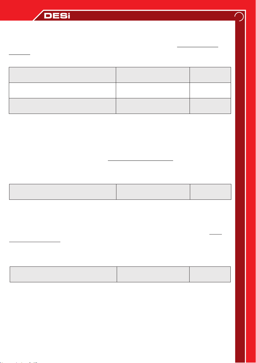
4.7. Programmable Relay
There is also a programmable relay output inside the outdoor siren.
To make the settings related to the relay, follow the instructions below when the alarm is
disarmed: [ADMIN PASS.] → <MENU> → <9> → VIEW THE INDICATOR
Relay is activated during alarm
Relay is activated when armed
Relay is activated when 5. Zone is
open circuit
Display (META / PRO)Feature
6. Zone / 6 solid means
enable, not means disable
RF Zone / RFI solid means
enable, not means disable
PWR / PWR solid means
enable, not means disable
Choice
Press <6> to
select.
Press <7> to
select.
Press <8>
to select.
Press <STAY> after you have finished your choice.
After this steps, the buzzer will give a warning tone and your choice will be active.
4.8. Wireless Detector Tamper Protection
The system alarms if the motion detector, magnetic contact and wireless detectors cover try
to open (the alarm needs to be armed). If you want tamper protection even when the system
is disarmed, follow the instructions below when the alarm is disarmed:
[ADMIN PASS] → <MENU> → <9> → VIEW THE INDICATOR
Feature Display (META / PRO) Choice
Checking the wireless detector cover tamper
protection when the alarm is not activated.
4. Zone / 4 solid means
enable, not means disable
Press <4>
to select.
11
Press <STAY> after you have finished your choice.
After this steps, the buzzer will give a warning tone and your choice will be active.
4.9. Adjusting Sound Alerts For Delay Time
If you want your system to beep during the delay time, follow the instructions below when
the alarm is disarmed:
[ADMIN PASS.] → <MENU> → <9> → VIEW THE INDICATOR
(META / PRO)
Feature
Standby and delay times warning tone
Display
5. Zone / 5 solid means
enable, not means disable
Choice
Press <5>
to select.
Press <STAY> after you have finished your choice.
After this steps, the buzzer will give a warning tone and your choice will be active.
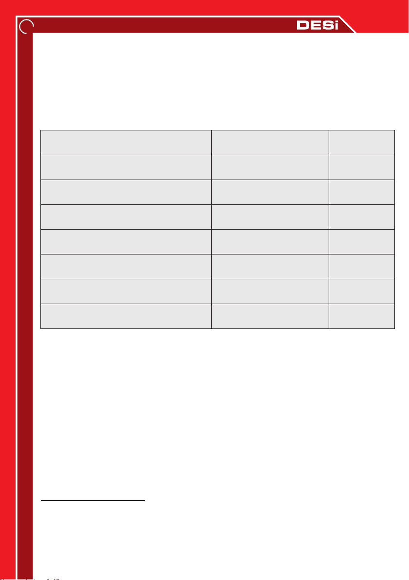
4.10. Zone Programming
Fully reportable area means 'zone'
in your system. If one detector is connected to the desired
area, 'zone' and detector have the same name. If more than one detector is connected to the
desired area, 'zone' will be the combine of all the detectors.
Page 12
12
The delayed zone feature is for preventing possible false alarms while trying to reach the
keypad. Your device has a 3-level delayed zone structure. The first detector (s) triggered
while entering the password “Level-1”, (If available) triggered 2. detector(s) “Level-2”, (If
available) triggered 3. detector(s) “Level-3“ set as delayed zone. If the 2nd or 3rd level is
triggered before the first level, system will give an alarm without delay.
The status of normal arming
The status of special arming type-1
The status of special arming type-2
Level 1 delayed zone feature
Level 2 delayed zone feature
Level 3 delayed zone feature
Continuous armed feature
Panic zone feature
Display (META / PRO)Feature
1. Zone / 1 solid means
enable, not means disable
2. Zone / 2 solid means
enable, not means disable
3. Zone / 3 solid means
enable, not means disable
4. Zone / 4 solid means
enable, not means disable
5. Zone / 5 solid means
enable, not means disable
6. Zone / 6 solid means
enable, not means disable
RF Zone / RFI solid means
enable, not means disable
PWR / PWR solid means
enable, not means disable
Choice
Press <1> to
select.
Press <2> to
select.
Press <3> to
select.
Press <4> to
select.
Press <5> to
select.
Press <6> to
select.
Press <7> to
select.
Press <8> to
select.
You can cancel the settings by pressing the <AREA> button. Press the <STAY> button to save
the settings and move to the 2nd zone. 2.Zone / 2 leds blinks then properties of 2nd zone will
be shown, with this way you can set the properties of all wired areas. You can press <MENU>
to exit programming at any step.
The properties of the wireless zones also set with similar way. The only difference is that,
after pressing the <MENU> button in the settings, press <2> not <1>. In order to make these
settings, the device must have a wireless detector. The zone numbers are determined
according to the order in wireless detectors are enrolled.
4.11. One by One Wireless Zone Programming
If there are too many wireless detectors in the system, adjusting them will take long time.
Instead, you can make changes by selecting the wireless zone. Follow the instructions below
when the alarm is disarmed:
[ADMIN PASS]→<MENU> → <3> → [ZONE NUMBER] → <STAY> → {See chart above} →
<STAY> → <MENU>
Page 13
4.12. Restore Factory Settings
We recommend to restore factory settings by the authorized
service. As a result of unauthorized service apply, electric
!
WARNING
shock and high level alarm sound may occur, also electronic
parts can be damaged. After this process, passwords, remote
control and wireless detectors will be deleted and all settings
made by the user will be restored to the factory settings.
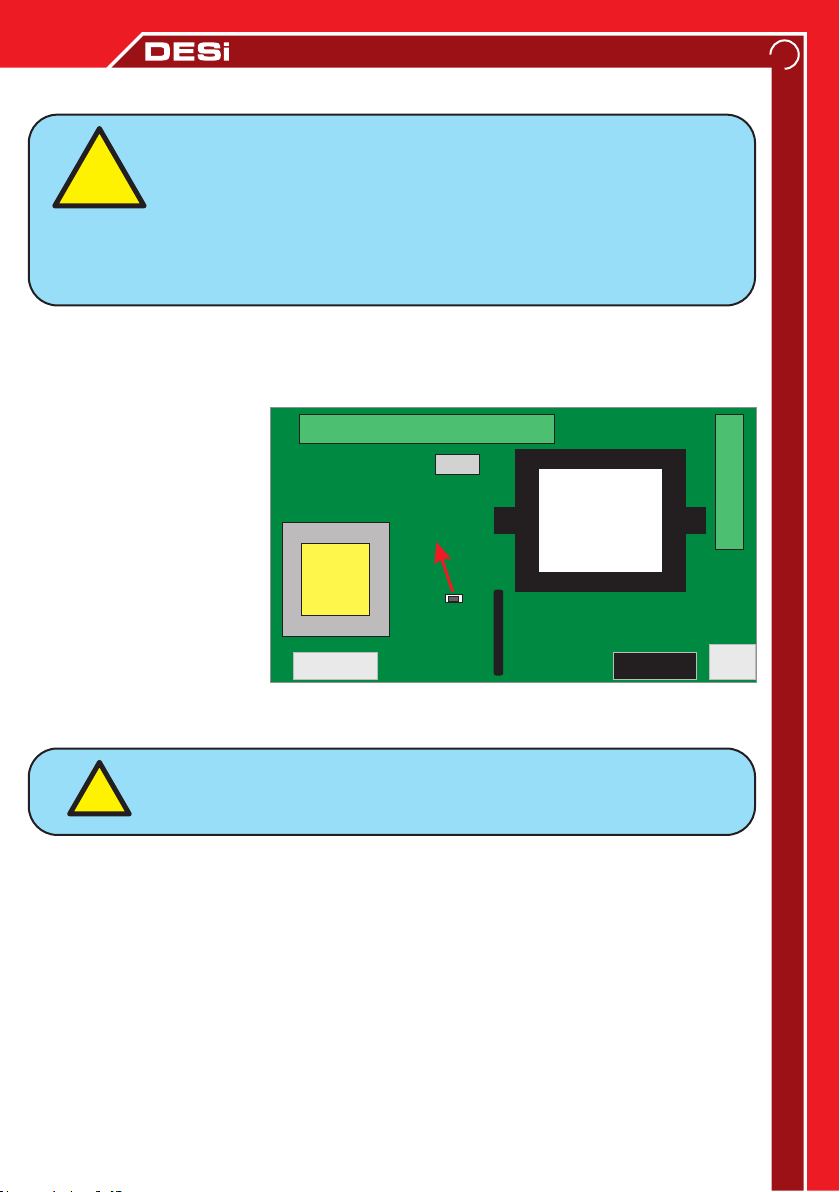
Restoring to the factory settings, carefully open the control panel while the device is energized.
When the panel cover opened, tamper protection will be activated and the siren will sound
loudly. Close the control panel tamper button with your hand and enter the password on the
keypad and press <DISARM> button to silence the siren.
CONNECTORS
Press and hold the enroll
button for 10 seconds
(until you hear a warning
tone). Then device restore
to factory settings.
ENROLLING
BUTTON
CONNECTORS
TRANSFORMER
13
Voice caller settings will not
affected.
4.13. Enrolling Remote Controller and Wireless Detector
TRANSFORMER
Tamper
Button
TouchPad
Connection
Control Panel Board
FUSE
220v
It is recommended to enroll remote controller and
!
Carefully open the control panel while the device is energized. When the panel cover opened,
tamper protection will be activated and the siren will sound loudly. Close the control panel
tamper button with your hand and enter the password on the keypad and press the
<DISARM> button to silence the siren. Press and hold the enroll button for 2 seconds:
Press the arm button of the remote controll to enroll. A long beep indicates that the device
has enrolled the controller.
Enrolling a wireless magnetic contact, move the magnet closer to the magnetic contact and
then move away (warning led on the magnetic contact blink).
Enrolling the wireless motion detector, press and release the tamper switch.
Enrolling the wireless shock detector, shake the detector for signal (the warning light on the
detector blink).
Enrolling wireless smoke detector, press the test button of the detector.
wireless detectors by the authorized service.
Page 14
14
5. VOICE CALLER SETTINGS (For models with phone call feature)
Your system has a telephone connection. In this way, the device can call up to 6 different
phone numbers and leave a 10-second voice message or it can be monitored every second by
the alarm monitoring center. In addition, you can arm/disarm or control the relay output of
your device by accessing it remotely via your phone.
5.1. Add / Delete Phone Numbers:
To programme phone numbers to call during an alarm, follow the instruction below when the
alarm is disarmed:
[ADMIN PASS.] → <MENU/ > → <4> → WARNING TONE → <MENU/ >
→ [CALL ORDER (1-6)] → [PHONE NUMBER] → <ENTER/#>
You have to repeat process for every each phone number. Press <AREA> button to cancel
process. If you want to delete a programmed phone number, press <ENTER / #> without
entering any phone number.
5.2. Changing the Voice Message:
“Your system is alarming, please respond.” is factory default voice caller message.
If you want to record a different message, the telephone has to connected directly to control
panel during installation, follow the instructions below when the alarm is disarmed:
[ADMIN PASS.] → <MENU/ > → <4> → WARNING TONE →<MENU/> → <7> → <1> →
RECORD YOUR MESSAGE (max 10sec.) → <2>
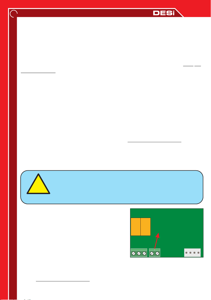
If phone is not connected to the phone port inside the control
!
WARNING
Carefully open the control panel while the device is
energized. When the panel cover opened, tamper
protection will be activated and the siren will sound
loudly. Close the control panel tamper button with
your hand and enter the password on the keypad and
press the <DISARM> button to silence the siren.
Connect your phone to 'PHONE OUTPUT' port. Then
turn back to instructions above.
5.3. Playback Of Recorded Voice Message
To listen recorded voice message with connected phone, follow the instructions
below when the alarm is disarmed:
[ADMIN PASS.] → <MENU/> → <4> → WARNING TONE → <MENU/> → <8>
panel, this must be done first. We recommended authorized
service to do this process.
PHONE OUTPUT
Page 15

5.4. Receiving / Canceling a Dial Tone:
If the telephone line of your device is connected to the switchboard, you can set the number
required to receive a dial tone by following instruction when the alarm is disarmed:
[ADMIN PASS.] → <MENU/ > → <4> → DIAL TONE HEARD → <MENU/ > → <0> → <9> →
[NUMBER TO RECEIVE DIAL TONE] → <ENTER/#>
If you press the <ENTER / #> button without entering any number at step [NUMBER TO
RECEIVE DIAL TONE] in the above instruction, it could cancel the dial tone from the
switchboard.
5.5. MF / PULSE Call Options:
MF mode is selected as the factory default setting. If there is noise on your telephone line
(and the system cannot call the phones), it has to try again with PULSE mode.
Follow the instuctions below for changing MF/PULSE modes when the alarm is disarmed:
[ADMIN PASS.] → <MENU/ > → <4> → WARNING TONE → <MENU/ > → <0> → <0> →
[press 1 for PULSE mode, press 0 for MF mode] → <ENTER/#>
5.6. Secure / Direct Call Selection:
Secure dialing allows device to start dial after receiving the dial tone (factory default setting).
If device cannot call due to interference on the telephone line, a direct dial option should be
tried by following the instruction when the alarm is disarmed:
[ADMIN PASS.] → <MENU/> → <4> → WARNING TONE → <MENU/ > → <0> → <1> →
[Press 0 for SAFE CALL, Press 1 for DIRECT CALL] → <ENTER/#>
15
5.7. Remote Programming Of Voice Call System
Programming can be done by remote access. First of all, call the telephone number
of the person who is going to program (you should call from the parallel phone line which
connected to device). After the normal call started, follow the instuctions below using device
keypad:
[ADMIN PASS.] → <MENU/> → <7>
The programming tone (beep beep tones) will hear from the phone and you can change the
settings using phone keys.
5.8. Restore Factory Settings (for Voice Call Options)
To delete all programmed phone numbers and reset the phone settings to factory default,
follow the instructions below when the alarm is disarmed:
[ADMIN PASS] → <MENU/> → <4> → <ENTER/#> → <MENU/> → <1> → <3>
Page 16

16
6. ALARM MONITORING CENTER CONNECTION SETUPS
Your system can connect to alarm monitoring centers which use the Ademco® Contact
ID® protocol. In this way, your system is monitored every seconds by alarm monitoring
center. Alarm monitoring services could give informations to you about arming/disarming
details. Also they could inform to law enforcement officers while systems is alarming.
6.1. Enable / Disable Calls to Alarm Monitoring Center
To change alarm monitoring center call settings, follow the instructions below when the alarm
is disarmed:
[ADMIN PASS.] → <MENU/ > → <4> → WARNING TONE → <MENU/ > → <0> → <2> →
{Press <1> to enable, press <0> to disable} → <ENTER/#>
6.2. Entering Subscriber Number to Alarm Monitoring Center
To enter your device the subscriber number given by the alarm monitoring center, follow the
instructions below when the alarm is disarmed:
[ADMIN PASS.] → <MENU/ > → <4> → WARNING TONE → <MENU/> → <0> → <8> →
{For first subscriber number press <1>, if you have second subscriber number press <2>} →
[SUBSCRIBER NUMBER - 4 Digit] → <ENTER/#>
6.3. Entering Alarm Monitoring Center Phone Numbers
To set the alarm monitoring center phone numbers, follow the instructions below when the
alarm is disarmed:
[ADMIN PASS.] → <MENU/> → <4> → WARNING TONE → <MENU/> →
{for first phone number press <1>, for second phone numbers press <2> } →
[ALARM MONITORING CENTER PHONE NUMBER] → <ENTER/#>
6.4. Forwarding Arming / Disarming Notifications to Alarm Monitoring Center
Device could forward the alarm arm/disarm notifications to the alarm monitoring center, follow
the instructions below when the alarm is disarmed:
[ADMIN PASS.] → <MENU/ > → <4> → WARNING TONE → <MENU/ > → <0> → <3>
{enable notification forwarding press <1>, disable notification forwarding press <0>} →
<ENTER/#>
6.5. Entering Personal Phone Numbers
Device could inform you when the alarm monitoring center cannot be reached. You can enter
personal phone numbers to memory 3, 4, 5 and 6. Follow the instructions below when the
alarm is disarmed:
[ADMIN PASS.] → <MENU/ > → <4> → WARNING TONE → <MENU/> → {for third phone
number press <3>, for fourth phone number press <4>, for fifth phone number press <5>, for
sixth number press <6>} → [PHONE NUMBER] → <ENTER/#>
Page 17
7. GSM MODULE SETTINGS (For GSM connectable models )
- First, pin code of the SIM card must be canceled and the SIM
card must be correctly installed on the GSM module before the
!
WARNING
If you purchased a product that includes a GSM module, the factory default setting is to make
calls through the GSM line. You may also want to use a landline on your system. To enable or
disable the landline, follow the instructions below when the alarm is disabled:
[ADMIN PASS.] → <MENU/> → <4> → WARNING TONE → <MENU/> → <0> → <7> → {to
enable using landline press <1> butonuna, to disable using landline press <0>} → <ENTER/#>
To choose which line the device will use first, follow the instructions below when the alarm is
not activated:
[ADMIN PASS.] → <MENU/> → <4> → WARNING TONE → <MENU/> → <0> → <6> → {to
choose landline first press <1>, to choose GSM line first press <0>} → <ENTER/#>
If the dive cannot make a call for any reason over the specified line, the system will switch to
an alternative line.
device is power on.
- After the device is power on(15-20 sec.), if the blue LED on the
gsm card starts flashing that means the sim card is working.
17
Page 18
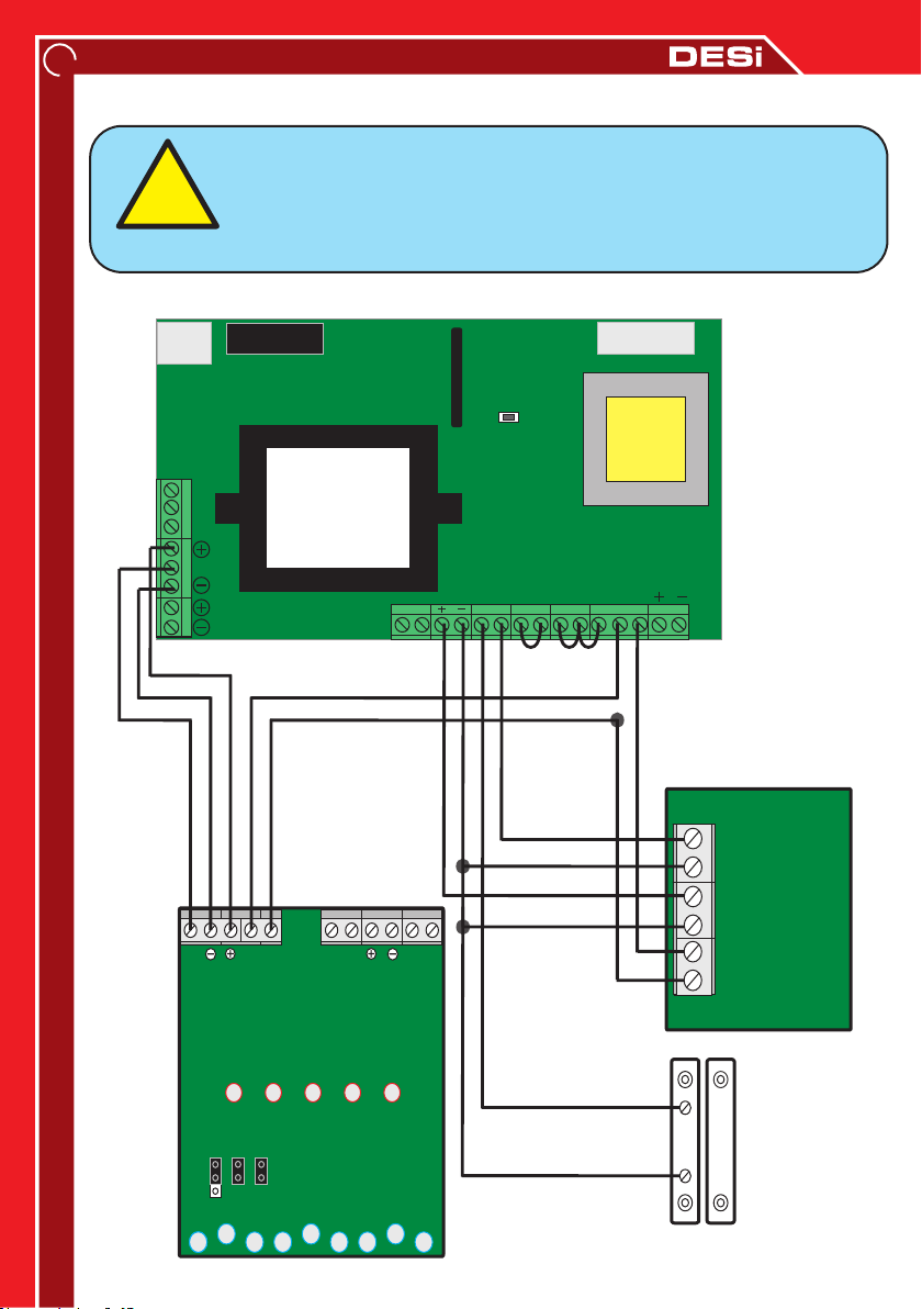
18
!
WARNING
220V
Input
INSTALLATION GUIDE -1
Before installation, please call DESi authorized services/dealers.
Do not allow to interfere your device anyone other than the
authorized service. You can visit www.desi.com.tr for a list of
current authorized services.
Detector and Outdoor Siren Connection
FUSE
Connection
Key Pad
TAMPER
BUTTON
NK
O
Programmable
Relay Output
NA
TTK
TTK
TRANSFORMER
NA
AkÜ
TAMP
External Siren Card
Siren
T
T R 12 V
Akü
Battery
R
SWCH
GND
A1 A2 A3 A4
GND
TRANSFORMER
GND
A5
A6
YD
Motion Detector
ALARM
Card
12V
0V
TAMPER
Magnetic
Contact
MAGNET
-TTK
+TTK
JP1
JP2
JP3
Page 19
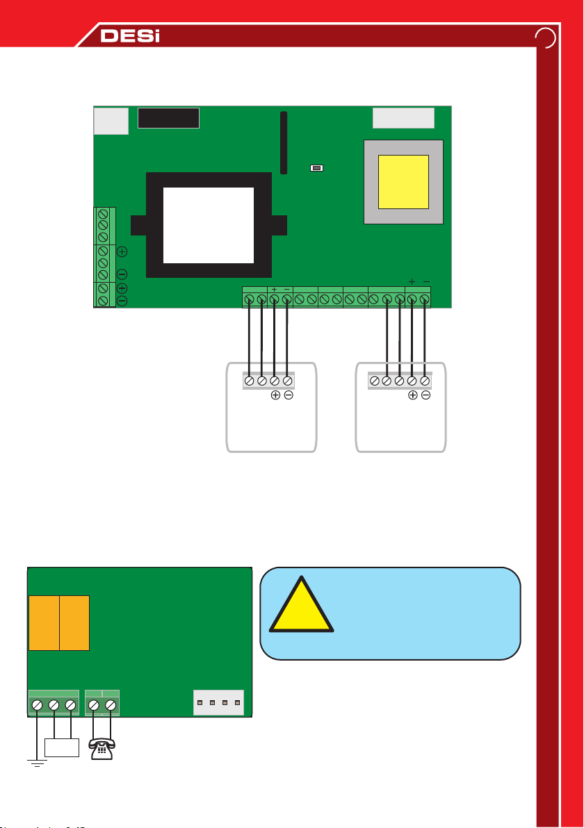
INSTALLATION GUIDE -2
Smoke Detector and External Keypad Connection
19
220V
Input
NK
O
NA
TTK
FUSE
TRANSFORMER
AkÜ
Connection
Key Pad
T R 12 V
T
R
Keypad
GND
A1 A2 A3 A4
GND
NO
TAMPER
BUTTON
TRANSFORMER
GND
A5
A6
NC
O
Smoke
Detector
YD
GND
Earth Line
LINE
Landline
TEL
Landline and Phone Connection
Be sure to connect the GND
!
WARNING
Main Center
Control Card
(4-way socket)
terminal to the building earth
line to protect it from
lightning and high voltage.
Page 20

DESi Alarm ve Güvenlik Sistemleri
A.Ş.
Topkapı Maltepe Cd. Anadolu Sk.
No:1 Topkapı - Maltepe / İstanbul
T. 444 33 74
F. 0212 576 64 77
www.desi.com.tr
Topkapı Maltepe Cd. Anadolu
Sk. No:1 Topkapı - Maltepe /
İstanbul
T. 444 33 74
F. 0212 576 64 77
 Loading...