

Page 1
TB-6132 January 2009 Page 1 of 3
Zero Volt Bench Top Ionizer Installation,
Operation, and Maintenance Instructions
ESD Systems.com • 432 Northboro Road Central • Marlboro, MA 01752 • (508) 485-7390 • Fax (508) 480-0257 • Website: ESDSystems.com
Installation
Remove the ionizer from the carton and inspect for
damage. Included with the unit should be:
1. Emitter cleaner
2. Power Cord (62204 Only), 220V Power Cord sold
separately
3. Certificate of Calibration
The input voltage should be set to your specification prior to
shipping. It can be verified or reset by referring to the
Maintenance section of these instructions.
Attach the stand to the unit by placing the plastic spacers
between the unit and the stand and securing in place using
the knurled knobs. If desired, attach rubber feet to each
corner of the bottom of the stand. Press feet firmly in place.
Before installing the unit, verify that the AC outlet is properly
connected to earth ground. The unit must have a good
earth ground to maintain proper balance.
Install the unit in the desired location, making sure that the
airflow will not be restricted. Be sure the ON/OFF switch,
located on the rear of the unit, is in the "OFF" position.
Plug the power cord into the unit and then into the
appropriate AC power source. This equipment has a
grounding type plug that has a third (grounding) pin. This
plug will only fit into a grounding type power outlet. If the
plug does not fit into the outlet, contact qualified personnel
to install the proper outlet. Do not alter the plug in any way.
Status of the unit can be monitored remotely via the RS485
data ports. Please contact the factory for the necessary
polling utility software.
INSTRUCTIONS MANUAL TB-6132
Made in America
© 2009 DESCO INDUSTRIES INC.
Employee Owned
Figure 1. 62204 Zero Vold Bench Top Ionizer
Operation
Set the fan speed switch on the rear of the unit to the LOW,
MED, or HI position. Higher airflow will result in faster
neutralization rates. Position the unit so that the maximum
airflow is directed at the items or area to be neutralized.
Turn the unit ON.
When the unit is first turned on, it conducts a self-test. The
audible alarm will sound and then the LED will cycle
through RED, YELLOW, and then GREEN. The LED will
remain GREEN during normal operation.
Balance Adjustment
The 62204 / 62210 (ZVI5100) is an auto-balancing unit.
However, tuning or manual adjustment can be
accomplished by inserting a small screwdriver or trimmer
adjustment tool into the balance adjustment hole located on
the right rear of the unit. To increase the output in a
positive direction, turn the potentiometer in a clockwise
direction. Conversely, to increase the output in a negative
direction, turn the potentiometer in a counter clockwise
direction.
Maintenance / Alarms
WARNING - RISK OF ELECTRIC SHOCK - These
servicing instructions are for use by qualified personnel
only. To reduce the risk of electric shock, do not perform
any servicing of internal parts unless you are qualified to do
so.
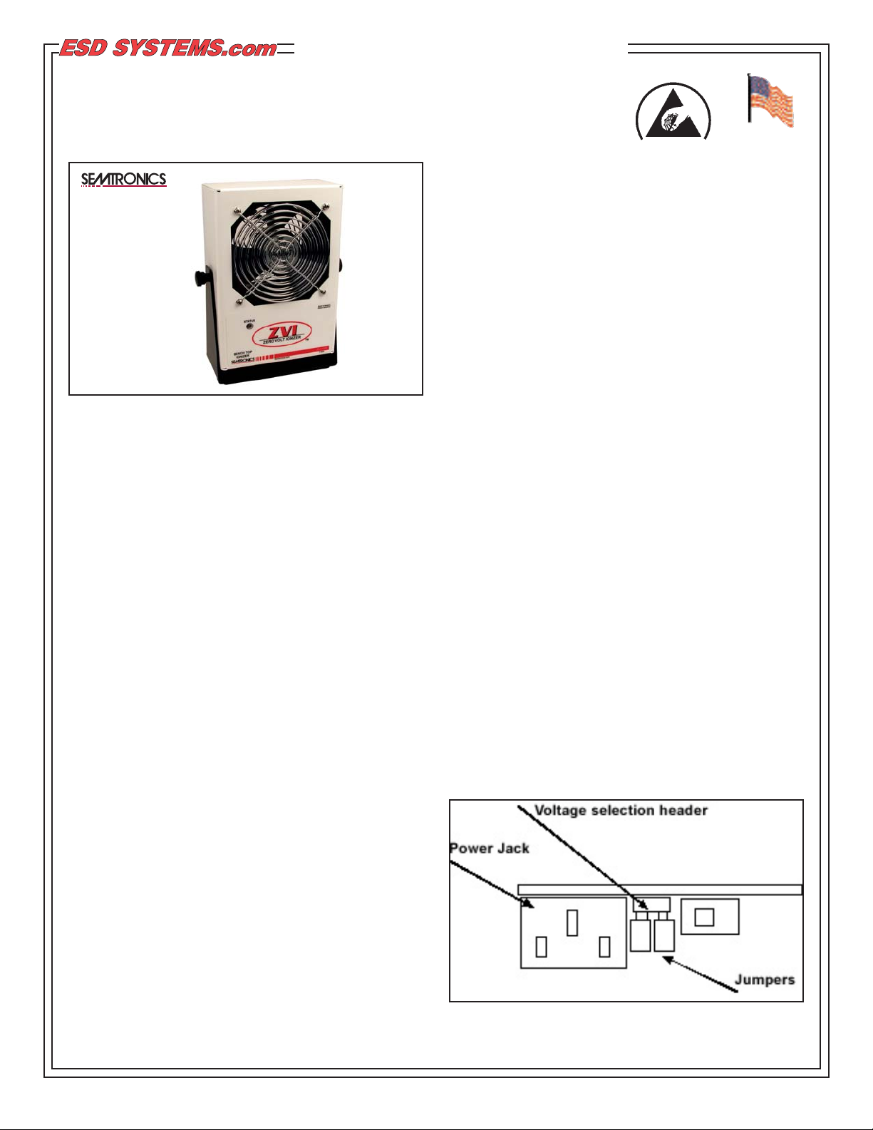
The input voltage may be verified or reset by removing the
back case by disengaging the 3 screws on back. NOTE:
The AC power cord MUST always be disconnected before
the unit is disassembled.
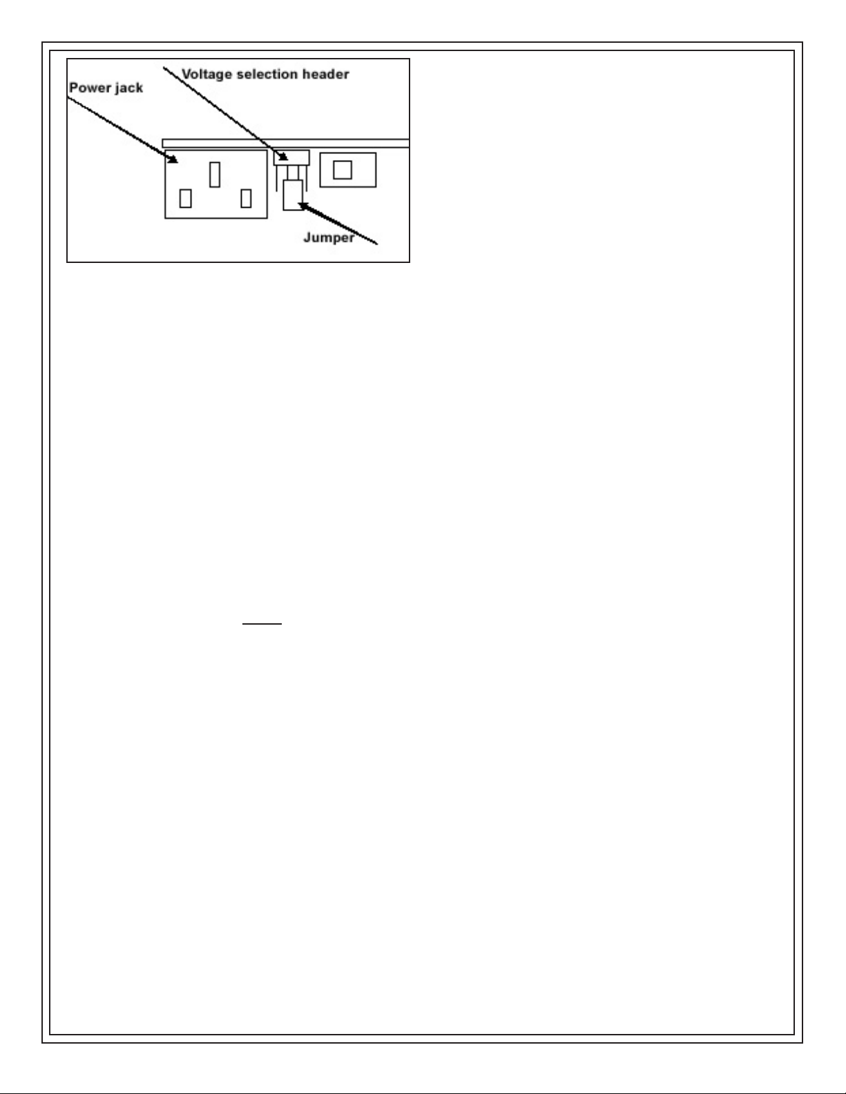
Input voltage is selected with the two internal jumpers as
shown below:
Figure 2. 110 Volt Jumper Setting
Page 2
ESD Systems.com • 432 Northboro Road Central • Marlboro, MA 01752 • (508) 485-7390 • Fax (508) 480-0257 • Website: ESDSystems.com
TB-6132 Page 2 of 3
© 2009 DESCO INDUSTRIES INC.
Employee Owned
Figure 3. 220 Volt Jumper Setting
It the supply voltage drops from 110 Volts to below 85
Volts or from 200 Volts to below 170 Volts, the unit will
shut down the audible alarm will beep and the LED will
blink RED. The unit will automatically reset when the
minimum voltage is restored.
Under normal conditions, the ionizer will attract dirt and
dust (especially on the emitter electrodes). To maintain
optimum neutralization efficiency and operation,
cleaning should be performed on a regular basis.
In the event of circuit failure, the unit will enter
shutdown mode.
When the unit enters shutdown mode, ionization will be
stopped, the LED on the front of the unit will change to
a steady of RED, and the audible alarm will sound
continuously. If the ionizer enters shutdown mode, it
must be turned OFF and then back ON to reset the
unit.
NOTE: The AC power cord MUST be disconnected
before the unit is disassembled for maintenance. The
emitter electrodes should be cleaned using the alcohol
cleaners included or a swab wet with Isopropyl alcohol.
First, turn the unit OFF and unplug the power cord.
Then remove the rear screen by disengaging the 4
screws on back. After cleaning the emitter electrodes,
reattach the rear screen using the 4 screws. Plug in
the power cord and turn the unit back ON.
The emitter electrodes should not require replacement
during the life of the unit with normal handling.
Replacement emitter electrodes can be ordered if
necessary.
Best practice would be to verify the balance of the unit
with a charge plate monitor after cleaning.
Specifications
• Air Flow
Three speed fan (125fpm -250fpm; 50-100cfm).
• Balance
±3 volt, typical; ±5 volts maximum.
(Temperature range: 65oF to 80oF, R.H.: 15% to 65%)
• Chassis
White powder coated aluminum housing.
• Dimensions ( with stand )
9.5: high x 6.0" wide x 3.1" deep.
• Emitter Points
.050" diameter pure tungsten for improved mechanical
strength and ionization stability.
• Fuse
250 mA slow blow.
• High Voltage Power Supply
5.5 kV DC nominal.
• Input Power
AC line power, internally selectable for 110/115 VAC50/60Hz or 220/230 VAC-50/60Hz.
• Ion Emission
Steady state DC with sense feedback.
• Mounting
Bench top tilt adjust frame.
• Ozone
Less than 0.05ppm
• Weight
4.5 pounds
NOTE: Unauthorized servicing or modifications to your
ionizer will void the product warranty and may create
dangerous conditions. Servicing should be performed
only at the factory, or by a Semtronics approved
technician.
Page 3

Contact and Warranty
ESD Systems
432 Northboro Road Central
Marlboro, MA 01752
Tel: (508) 485-7390
Fax: (508) 480-0257
NOTE: Unauthorized servicing or modifications to
your monitor will void the product warranty and may
create dangerous conditions. Servicing should be
performed only at the factory, or by a Semtronics
approved technician.
LIMITED WARRANTY
ESD Systems expressly warrants that for a period of
one (1) year from the date of purchase, the ESD
Systems Footwear Tester will be free of defects in
material (parts) and workmanship (labor). Within the
warranty period, a unit will be tested, repaired, or
replaced at our option, free of charge. Call Customer
Service at 909-627-8178 (Chino, CA) or 781-821-8370
(Canton, MA) for Return Material Authorization (RMA)
and proper shipping instructions and address. Include
a copy of your original packing slip, invoice, or other
proof of date of purchase. Any unit under warranty
should be shipped prepaid to the Semtronics factory.
Warranty replacements will take approximately two
weeks. If your unit is out of warranty, ESD Systems
will quote repair charges necessary to bring your unit
up to factory standards. Call Customer Service at 909627-8178 for proper shipping instructions and address.
Ship your unit freight prepaid.
WARRANTY EXCLUSIONS
THE FOREGOING EXPRESS WARRANTY IS MADE
IN LIEU OF ALL OTHER PRODUCT WARRANTIES,
EXPRESSED AND IMPLIED, INCLUDING
MERCHANTABILITY AND FITNESS FOR A
PARTICULAR PURPOSE WHICH ARE
SPECIFICALLY DISCLAIMED. The express warranty
will not apply to defects or damage due to accidents,
neglect, misuse, alterations, operator error, or failure to
properly maintain, clean or repair products.
LIMIT OF LIABILITY
In no event will ESD Systems or any seller be
responsible or liable for any injury, loss or damage,
direct or consequential, arising out of the use of or the
inability to use the product. Before using, users shall
determine the suitability of the product for their
intended use, and users assume all risk and liability
whatsoever in connection therewith.
ESD Systems.com • 432 Northboro Road Central • Marlboro, MA 01752 • (508) 485-7390 • Fax (508) 480-0257 • Website: ESDSystems.com
TB-6132 Page 3 of 3
© 2009 DESCO INDUSTRIES INC.
Employee Owned
Neutralization (Decay) Times
The comparative efficiency of benchtop ionizers is
determined by a standard test published by the ESD
Association: Standard S3.1. Typical positive and
negative decay times (from 1000 volts to 100 volts)
measured using this standard are shown below. The
performance of the ionizer was measured with the unit
positioned as shown, with the fan speed on high, and
without a filter.
 Loading...