

Page 1
TB-6110 January 2009 Page 1 of 3
ESD Systems.com • 432 Northboro Road Central • Marlboro, MA 01752 • (508) 485-7390 • Fax (508) 480-0257 • Website: ESDSystems.com
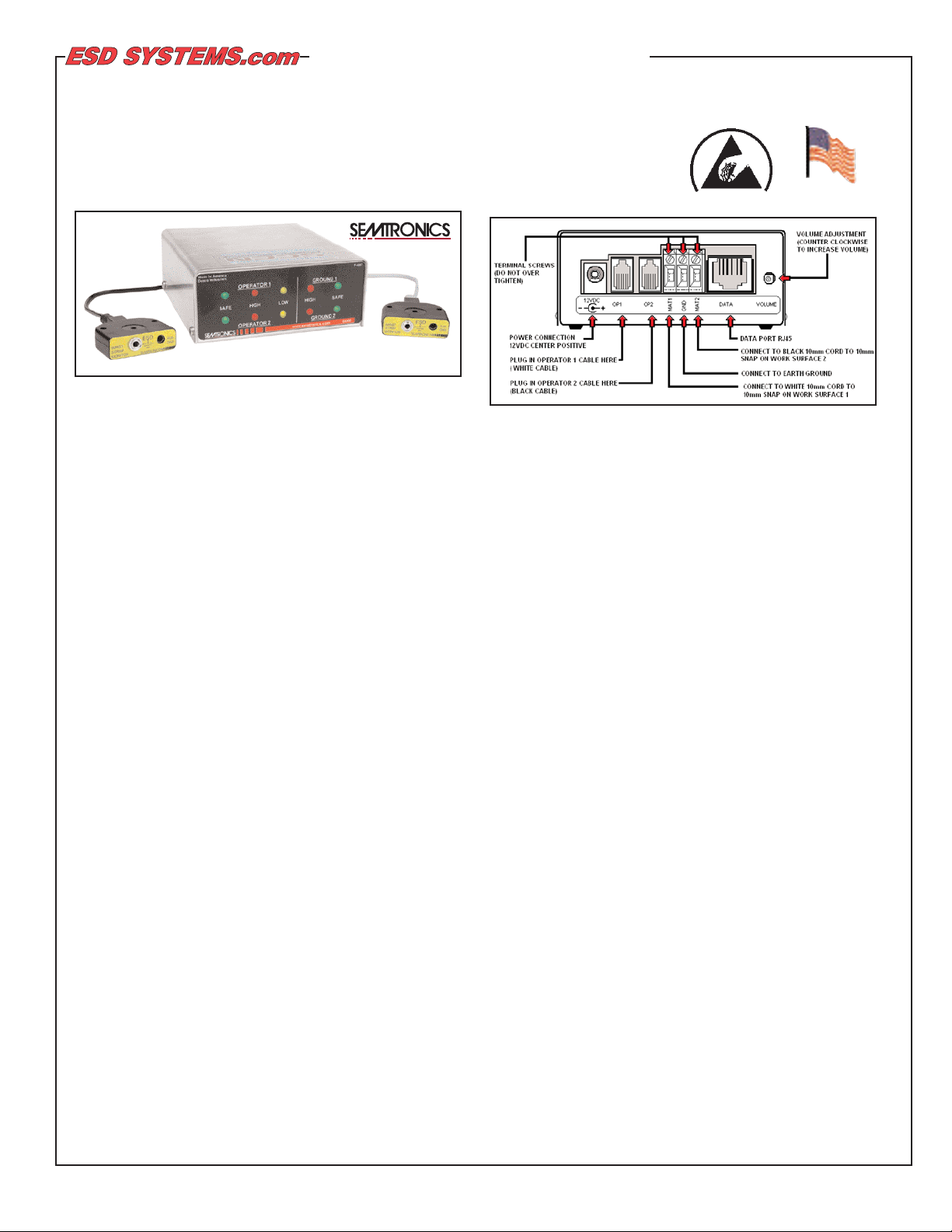
Figure 1. Dual-Wire Dual-Operator Programmable Monitor
Description
Continuous monitors pay for themselves, by improving quality,
productivity, and eliminating daily wrist strap testing and test
result logging. Per ESD-S1.1 paragraph 6.1.3 Frequency of
Functional Testing, “The wrist strap system should be tested
daily to ensure proper electrical value. Daily testing may be
omitted if constant monitoring is used.”
Per ESD Handbook TR20.20 paragraph 5.3.2.4.4, “Typical test
programs recommend that wrist straps that are used daily
should be tested daily. However, if the products that are being
produced are of such value that knowledge of a continuous,
reliable ground is needed, and then continuous monitoring
should be considered or even required.”
The Semtronics 62030 Dual-Wire Dual-Operator
Programmable Monitor can maintain two work surfaces and
two operators at ground potential to virtually eliminate the risk
of ESD damage. The highly visible LED display and audible
alarm makes it easy to monitor the status of the work surfaces
and operators. The 62030 Dual-Wire Dual-Operator
Programmable Monitor uses Semtronics patented* dual
resistive loop technology. No other method is as direct and
reliable. Both work surfaces, and individual operator resistance
limits, can be programmed and re-configured as required. If the
ground potential of either work surface or operator is lost the
62030 immediately alarms (both audible and visual). The
62030 is unaffected by capacitance variations associated with
personnel and environmental conditions.
The 62030 Dual-Wire Dual-Operator Programmable Monitor
features:
• Monitoring of two operators independently.
• Monitoring of two ground connections (work surfaces)
independently.
• Fully independent alarming conditions: audible and visual.
• Independent LED status lights for each operator and each
ground connection (work surface.)
• Two independent operator wrist strap ground point remotes
with 10’ cables.
© 2009 DESCO INDUSTRIES INC.
Employee Owned
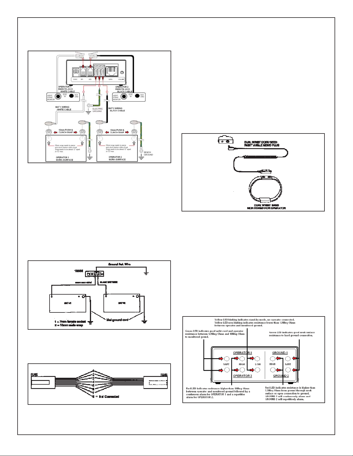
Figure 2. 62030 Rear View
Installation
Remove the monitor from its packaging and inspect for any
shipping damage. Included with each 62030 Dual-Wire DualOperator Programmable Monitor should be:
1 Monitor 1 Hardware Kit (62012)
1 White Operator Remote 3 Grounding Wires (SE-5136)
1 Black Operator Remote 1 Mat Ground Cord (Grey)
1 AC Adapter 1 Mat Ground Cord (Black)
4 Push Clinch Snaps
A. Determine the mounting location of the 62030 monitor. The
front panel should be visible to a supervisor.
B. Determine the mounting location of the operator remotes.
The white remote is for operator #1 and the black remote is for
operator #2. Make sure that each remote is located so that the
remote leads reach the monitor but are convenient for the
operator.
C. Attach the operator remotes to the bench or other surface
using the provided screws.
D. Attach the tinned wire ends of the mat wires to the
appropriate screw terminal connection on the rear of the unit.
(See Figure 2). The white wire is for operator #1 and the black
wire is for operator #2.
E. If not already done, attach the work surface to workstation
common point ground using the pictured ground wires. For
mats, attach the grounding point snaps at the ends of the
ground monitor cords to the grounding point snaps on the work
surface. These ground monitor cords are used for sensing
whether or not the unit is properly grounded. Refer to figure 3
for snap-plate fitting diagram and for laminates or other hard
surfaces with a buried conductive layer.
F. Attach the tinned wire end of the black ground-reference
wire to the center position of the screw terminal block on the
rear of the unit. Attach the ring terminal end to an alternate
ground point. It is important that this ground wire is attached to
a separate ground point other than the work surface ground
*U.S. Patents 6,052,053 and 6,205,408
Tech Brief
Dual-Wire Dual-Operator Programmable Monitor
Installation, Operation, and Maintenance
Made in America
TECHNICAL BULLETIN TB-6110
Page 2
cords from the previous step to ensure proper independent
monitoring. The faceplate screw of a grounded AC wall outlet
may provide a convenient connection point.
Figure 3. Mat Grounding
G. Route the work surface monitor wires from the back of the
monitor unit, to the snaps/bolts attached to the grounded
surfaces. Attach the white ground wire to the operator #1 work
surface and the black ground wire to the operator #2 work
surface.
H. Route the operator remote wires to the monitoring unit and
insert the modular plugs into the appropriate jacks on the rear
of the unit. (See Figure 2)
Mat Grounding
It is recommended to connect the mat wire (10mm snap) from
the monitor and the mat ground wire (10mm snap) to two
separate points on the bench mat as in Figure 4.
Figure 4. Mat Grounding
I. If using a TR2000 SmartHub along with the 62030, construct
a data output cable. Refer to Figure 5.
Figure 5. Data Cable
TB-6110 Page 2 of 3
J. Plug the DC power supply plug into the power jack in the
rear of the unit. Route the wire from the supply to a nearby
AC outlet and plug the power supply into the outlet. Make sure
the voltage and frequency match those listed on the AC
adapter. The monitor should now be powered.
Operation
Wrist Strap Connections
Once all the connections described above have been made
and the unit has been powered up, the unit is ready for operation. Install operator wrist straps and ground wires. Dual
snaps on the operator ground wires attach to the wristband
snaps and the mono plug on the other end inserts into the
operator remote as illustrated in Figure 6. The operator's
monitoring is in "STANDBY" mode until the operator's ground
wire is plugged into the remote jack for that station.
Figure 6. Operator Ground Cords and Wrist Snaps
NOTE: The operator remote has two jacks. One is a 3.5 mm
mono jack for use with a dual wrist strap. Adual operator
ground wire plugged into this jack will be monitored. The other
jack is a grounded banana jack for use with a single conductor
operator ground wire. This is a grounded guest hook-up that is
not monitored.
Status Indicators
The audible alarm for Operator 1 and Ground 1 is continuous.
The audible alarm for Operator 2 and Ground 2 is a repetitive
beep. If a fault condition exists for both operators and/or both
grounds, the alarm will sound continuously. The alarm volume
may be adjusted with the potentiometer on the rear of the unit.
Refer to Figure 7.
Figure 7. Status Indicator
© 2009 DESCO INDUSTRIES INC.
Employee Owned
ESD Systems.com • 432 Northboro Road Central • Marlboro, MA 01752 • (508) 485-7390 • Fax (508) 480-0257 • Website: ESDSystems.com
Page 3

TB-6110 Page 3 of 3
© 2009 DESCO INDUSTRIES INC.
Employee Owned
The 62030 provide status indicators for the following
conditions:
• Standby - The operator is not plugged into the remote. This
condition is indicated by a flashing yellow LED in the operator
section of the display.
• Operator Fail High - The operator's series resistance is
greater than the upper resistance limit. This condition is
indicated by the red LED in the Operator section of the
display along with an audible alarm
• Operator Fail Low - The operator's series resistance is less
than 1.9Meg Ohm. This condition is indicated by the flashing
yellow LED in the Operator section of the display.
• Operator Pass/Safe - The operator's series resistance is
within the range of 1.9Meg Ohm to the upper resistance limit.
This condition is indicated by the green LED in the Operator
section of the display.
• Ground Fail High - The resistance from the mat connection
to ground is greater than 3.5Meg Ohm. This condition is
indicated by the red LED in the Ground section of the display
as well as an audible alarm.
• Ground Pass Safe - The resistance from the mat
connection to ground is less than 3.5Meg Ohm. This
condition is indicated by the green LED in the Ground section
of the display.
The resistance values quoted above are the Factory Defaults.
These numbers will vary depending on the configuration.
Changing the Test Voltage
The 62030 can be set for a test voltage of either +5V or +8V.
Reducing the test voltage will result in a lower finger-tip
voltage on the operator. To change the test voltage you must
set two jumpers inside the unit.
Remove the four case screws and open the 6110 case. BE
SURE TO OBSERVE ESD PRECAUTIONS, AS THERE ARE
ESD SENSITIVE DEVICES INSIDE THE CASE. Refer to
Figure 8 for setting the test voltage to +5V and +8V.
Specifications
• Two user selectable resistance levels of 10 Meg ohms or
35 Meg ohms.
• Two user selectable test voltage settings of +5V or +8V.
• SCCN compatible data output.
• Stainless Steel housing.
• Size: 4.3" W x 4.4" D x 1.8" H
• Plug-in power supply: 110 VAC/60Hz input, 12VDC/500mA
output or 230VAC/50Hz input, 12VDC/500mA output.
2.5mm connector - center positive. Any alternate
transformer must comply with the Safety Extra Low Voltage
(SELV) insulation requirements.
• Important: This appliance has a metal casing but the earth
connection is only used for operational purposes. It is
considered to be class I and tested as class II. The power
supply connection plug is accessible to the user and there
is no safety insulation inside the Semtronics Item #62030.
Therefore the insulation of the power supply is critical.
• Rated Power consumption: 3.6VA.
Figure 8. Jumper Setting for various test voltages
Environmental Conditions
• Suitable for indoor use only at altitudes not exceeding
6500ft. (2Km)
• Maximum relative humidity of 80% up to 88°F (31°C)
decreasing linearly to 50% @104°F (40°C)
• Pollution degree 2 per IEC 644
• Temperature range of 41°F (5°C) to 104°F (40°C)
Limited Warranty
ESD Systems.com expressly warrants that for a period of one (1) year from the date
of purchase, Semtronics Dual-Operator Programmable Monitor will be free of
defects in material (parts) and workmanship (labor). Within the warranty period, the
product will be tested, repaired, or replaced at our option, free of charge. Call our
Customer Service Department at
508-485-7390
(Marlboro, MA) for a Return
Material Authorization (RMA) and proper shipping instructions and address. Include
a copy of your original packing slip, invoice, or other proof of purchase date. Any
unit under warranty should be shipped prepaid to the ESD Systems.com factory.
Warranty repairs will take approximately two weeks.
If your unit is out of warranty, call Customer Service at
508-485-7390 (Marlboro,
MA)
for a Return Material Authorization (RMA) and proper shipping instructions
and address. ESD Systems.com will quote repair charges necessary to bring your
unit up to factory standards.
Warranty Exclusions
THE FOREGOING EXPRESS WARRANTY IS MADE IN LIEU OF ALL OTHER
PRODUCT WARRANTIES, EXPRESSED AND IMPLIED, INCLUDING
MERCHANTABILITYAND FITNESS FOR A PARTICULAR PURPOSE WHICH
ARE SPECIFICALLY DISCLAIMED. The express warranty will not apply to defects
or damage due to accidents, neglect, misuse, alterations, operator error, or failure
to properly maintain, clean or repair products.
Limit of Liability
In no event will ESD Systems.com or any seller be responsible or liable for any
injury, loss or damage, direct or consequential, arising out of the use of or the
inability to use the product. Before using, users shall determine the suitability of
the product for their intended use, and users assume all risk and liability
whatsoever in connection therewith.
Dip Swi t ches
Function Down Up
Switch 1 Input Vol tage 8v 5v
Switch 2 5v 8v
Switch 3
W rist Strap
High limit
35m 10m
ESD Systems.com • 432 Northboro Road Central • Marlboro, MA 01752 • (508) 485-7390 • Fax (508) 480-0257 • Website: ESDSystems.com
 Loading...