

Page 1
TB-6106 January 2009 Page 1 of 4
Footwear Tester Installation,
Operation and Maintenance
ESD Systems.com • 432 Northboro Road Central • Marlboro, MA 01752 • (508) 485-7390 • Fax (508) 480-0257 • Website: ESDSystems.com
Description
The Semtronics 62090 Footwear Tester is a 3-state touch
tester designed for fast and frequent testing of ESD
personnel footwear. The 62090 tester can be used to verify
that the ESD footwear resistance circuit is within the proper
limits. It can be setup to test a 1M - 100M circuit (foot
grounders) or a 1M - 1G circuit (dissipative shoes).
This unit can be used as one of the tools to fulfill the ANSI
ESD S20.20 paragraph 6.1.3.2 Compliance Verification
Plan. "Verification should include routine checks of the
Technical Requirements of the Plan." The Footwear Tester
incorporates a unique dual test circuit design which
improves test accuracy.
ESD TR1.0-01-01 section 1.0 Introduction
"Since people are one of the greatest sources of static
electricity and ESD, proper grounding is paramount. One of
the most common ways to ground people is with a wrist
strap. Ensuring that wrist straps are functional and are
connected to people and ground is a continuous task."
ESD SP9.2 APPENDIX B - Foot Grounder Usage Guidance
"Compliance verification should be performed prior to each
use (daily, shift change, etc.). The accumulation of
insulative materials may increase the foot grounder system
resistance. If foot grounders are worn outside the ESD
protected area testing for functionality before reentry to the
ESD protected area should be considered."
OPERATION
NOTE: Refer to the technical manual for your footgrounding devices. Not all foot-grounding devices are
similar and it is very important that you review their
specifications.
INSTRUCTIONS MANUAL TB-6106
Made in America
© 2009 DESCO INDUSTRIES INC.
Employee Owned
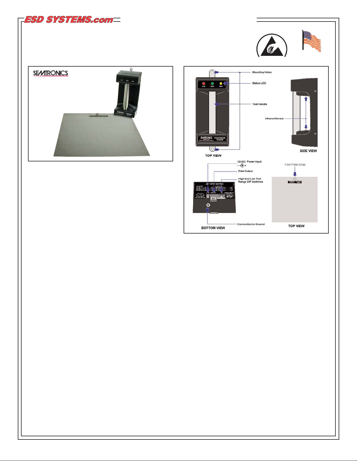
Figure 1. 62090 Footwear Tester
Figure 2. Footwear Tester and Foot Plate Features and
Components
Packaging
1 Footwear Tester
1 Foot Plate
1 12 VDC Power Adapter (500 mApositive center)
1 Banana Plug to Ring Terminal Cord
1 Snap to Ring Terminal Cord
1 NIST Certificate of Calibration
Installation
Mounting the Tester
• Verify that the correct low and high test limits are
correctly set before mounting the tester to a wall.
Refer to the overlay located on the bottom of the tester.
(See table on Page 4 for more details)
• Be sure to install the Footwear Tester and foot plate
away from any high voltage power supplies, power
boxes, chemicals, and other safety hazards.
• Place in a convenient area where waiting lines may
be allowed to form.
• Mount the tester in the upright position (See Figure 2)
approximately 4 feet above floor level.
• Place the foot plate directly below the Footwear
tester.
Page 2
ESD Systems.com • 432 Northboro Road Central • Marlboro, MA 01752 • (508) 485-7390 • Fax (508) 480-0257 • Website: ESDSystems.com
Connecting the Footwear Tester and Foot Plate
I. Using the banana plug to ring terminal cord, connect
the banana plug to the banana jack on the bottom side
of the tester and the ring terminal to a known ground.
II. Using the snap to ring terminal cord, snap the cord
to the foot plate and the ring terminal to a known
ground.
III. After all connections have been made, insert the
female plug of the power adapter to the bottom of the
tester.
IV. Plug the power adapter into an appropriate power
source. The yellow "HIGH" LED will turn on indicating
standby mode.
Calibration
ESD Handbook TR 20.20 paragraph 5.2.3 "If the
contact area between the bottom of the foot and the
floor is not continuous, charge generation may occur
especially when a person is walking. Heel straps must
be worn on both feet to minimize the amount of time
that the body of the person is isolated from ground
while walking."
Note: Consider Semtronics Continuous Monitors
Per ESD Handbook TR 20.20 paragraph 5.3.2.4.4
"Typical test programs recommend that wrist straps
that are used daily should be tested daily. However, if
the products that are being produced are of such value
that knowledge of a continuous, reliable ground is
needed, and then continuous monitoring should be
considered or even required."
TB-6106 Page 2 of 4
It is recommended that calibration of this unit be
handled by a qualified technician. There are no user
adjustable potentiometers, but there are DIP switches
to adjust the ranges.
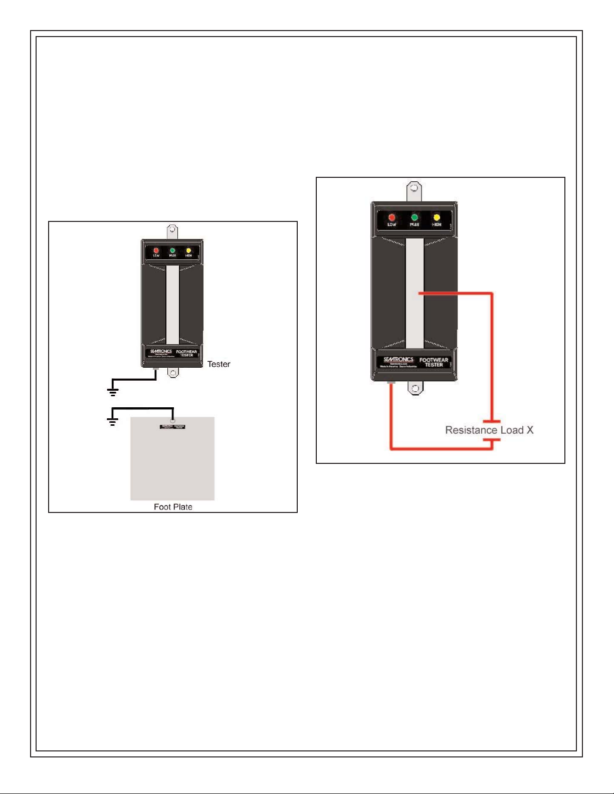
The Footwear Tester can be calibrated by using a 1k 2G range decade box to load a resistance across the
stainless steel handle and the banana jack located on
the bottom of the tester. Resistance Load X from the
decade box is the value that will be indicated as a Fail
LOW, Fail HIGH, or PASS.
© 2009 DESCO INDUSTRIES INC.
Employee Owned
Figure 3. Connecting the Footwear Tester and Foot Plate
Figure 4. Applying a Load Resistance to the Footwear Tester
Page 3

Operation
NOTE: Refer to the technical manual for your foot-grounding devices. Not all foot-grounding devices are similar and it is
very important that you review their specifications.
The tester measures the total resistance between both of the grounding devices (heel ground, dissipative shoes, etc). With
the grounding devices properly attached to the operator's feet, the operator should then place one foot on the foot plate and
grab the stainless steel handle. The tester will react in one of the following ways:
Green PASS LED The total resistance is within the limit settings
Yellow Fail HIGH LED + Audible Alarm The total resistance is above the high limit setting
Red Fail LOW LED + Audible Alarm The total resistance is below the low limit setting
If the test results are questionable remove both feet from the foot plate and wait 8 seconds before testing again.
The test limits can be adjusted by manipulating the DIP switches located at the bottom of the tester (See table on Page 4 for
more details).
Be sure to periodically clean the foot plate to ensure accurate testing.
Specifications
Test Ranges and Limits Table
ESD Systems.com • 432 Northboro Road Central • Marlboro, MA 01752 • (508) 485-7390 • Fax (508) 480-0257 • Website: ESDSystems.com
TB-6106 Page 3 of 4
© 2009 DESCO INDUSTRIES INC.
Employee Owned
Dimensions
Figure 4. Footwear Tester and Foot Plate Dimensions
Weight
Tester: 0.9 lbs / 0.41 kg
Foot Plate: 1.9 lbs / 0.86 kg
Page 4

ESD Systems.com • 432 Northboro Road Central • Marlboro, MA 01752 • (508) 485-7390 • Fax (508) 480-0257 • Website: ESDSystems.com
© 2009 DESCO INDUSTRIES INC.
Employee Owned
TB-6106 Page 4 of 4
Troubleshooting
1. Periodically clean the stainless steel foot plate
2. Check all cords for proper connections
NOTE:
The Yellow Fail HIGH LED will remain on when the unit
is not being used (standby mode).
No Alarm will sound until the stainless steel handle is
grabbed.
Contact and Warranty
ESD Systems
432 Northboro Road Central
Marlboro, MA 01752
Tel: (508) 485-7390
Fax: (508) 480-0257
NOTE: Unauthorized servicing or modifications to
your monitor will void the product warranty and may
create dangerous conditions. Servicing should be
performed only at the factory, or by a Semtronics
approved technician.
LIMITED WARRANTY
ESD Systems expressly warrants that for a period of
one (1) year from the date of purchase, the ESD
Systems Footwear Tester will be free of defects in
material (parts) and workmanship (labor). Within the
warranty period, a unit will be tested, repaired, or
replaced at our option, free of charge. Call Customer
Service at 909-627-8178 (Chino, CA) or 781-821-8370
(Canton, MA) for Return Material Authorization (RMA)
and proper shipping instructions and address. Include
a copy of your original packing slip, invoice, or other
proof of date of purchase. Any unit under warranty
should be shipped prepaid to the Semtronics factory.
Warranty replacements will take approximately two
weeks. If your unit is out of warranty, ESD Systems
will quote repair charges necessary to bring your unit
up to factory standards. Call Customer Service at 909627-8178 for proper shipping instructions and address.
Ship your unit freight prepaid.
WARRANTY EXCLUSIONS
THE FOREGOING EXPRESS WARRANTY IS MADE
IN LIEU OF ALL OTHER PRODUCT WARRANTIES,
EXPRESSED AND IMPLIED, INCLUDING
MERCHANTABILITY AND FITNESS FOR A
PARTICULAR PURPOSE WHICH ARE
SPECIFICALLY DISCLAIMED. The express warranty
will not apply to defects or damage due to accidents,
neglect, misuse, alterations, operator error, or failure to
properly maintain, clean or repair products.
LIMIT OF LIABILITY
In no event will ESD Systems or any seller be
responsible or liable for any injury, loss or damage,
direct or consequential, arising out of the use of or the
inability to use the product. Before using, users shall
determine the suitability of the product for their
intended use, and users assume all risk and liability
whatsoever in connection therewith.
 Loading...