

Page 1
TB-5531 December 2008 Page 1 of 6
plywood, fiber board, partical board tables and bench
tops with conventional contact adhesives. It is
resistant to most solvents and greatly exceeds the
NEMA specification for wear resistance. The NVMT
brand and ESD protective symbols are featured on
laminate sheets for protection and auditing purposes.
Installation
NVMT is designed to be used as a portable
worksurface or laminated to wooden tables or bench
tops with conventional contact adhesive.
1. Prepare the face of the substrate. It should be
clean, dry and free of all contaminants which would
interfere with adhesion. All the materials, NVMT,
substrate and cement, must be allowed to condition
at 70°F to 75°F and 45-50 percent relative humidity
for 48 hours prior to assembly.
2. Stir the adhesive thoroughly and apply an even coat
of adhesive by either spray, roller or brush to both
the substrate face and the NVMT back. Do not
allow coated surfaces to touch. Allow the cement to
dry. When bonding to plywood, apply a second coat
if the first coat completely penetrates the wood. Use
uncoated wood strips to assist in connecting coated
surfaces.
3. Place thin, uncoated, wooden strips 12 inches apart
across the substrate face. This will keep coated
surfaces apart; bonding will occur once contact is
made.
4. Position the over-cut NVMT sheet on top of the
wooden strips.
Figure 3. NVMT sheet on wooden strips
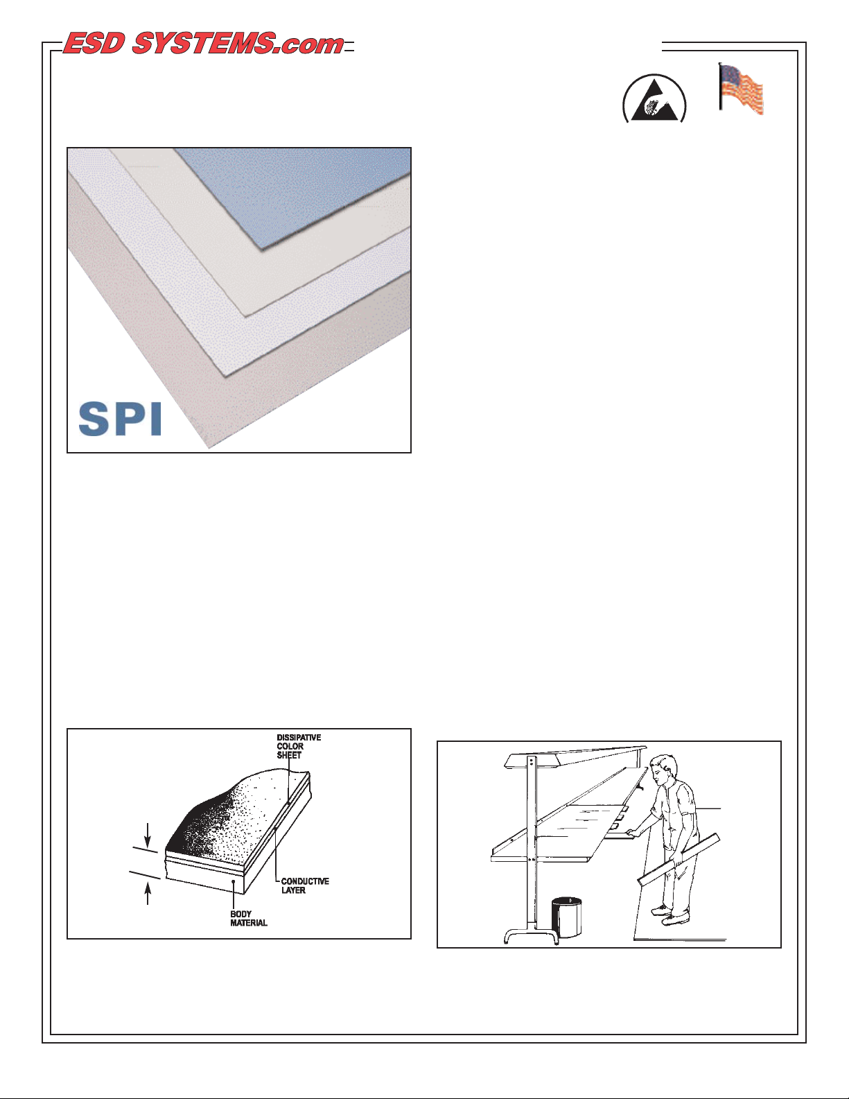
Figure 1. NVMT Protective Laminate
Blue, Gray, Beige, White, Almond
Description
NVMT is a high pressure static dissipative laminate
designed for workbench tops used in the manufacture
and assembly of ESD susceptible electronic
components. NVMT meets ANSI/ESD S20.20
requiring RTG <109Ohms per ESD S4.1 and
antistatic low tribocharging materials <200 volts per
ESD STM 4.2. Its multi-layer construction features a
conductive layer which ensures dissipative properties
independent of ambient humidity. NVMT shows
superior abrasion resistance and provides rapid, nonsparking charge dissipation. It can be laminated to
Figure 2. NVMT layered construction
ESD Systems.com • 432 Northboro Road Central • Marlboro, MA 01752 • (508) 485-7390 • Fax (508) 480-0257 • Website: ESDSystems.com
NVMT St atic Protective Laminate
Inst allation and Maintenance
0.038 IN.
THICK
Made in America
© 2008 DESCO INDUSTRIES, INC.
Employee Owned
TECHNICAL BULLETIN TB-5531
Page 2
TB-5531 Page 2 of 6
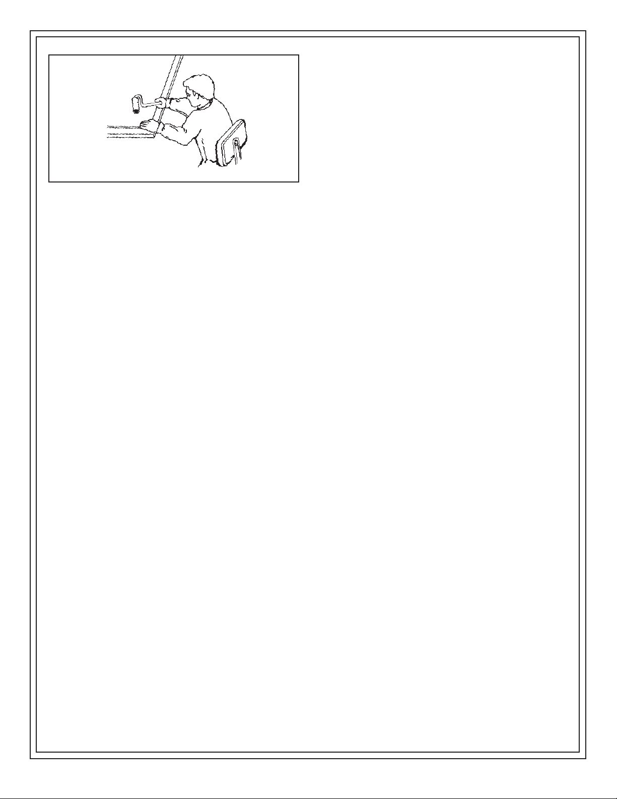
Figure 4. Wooden block and rubber mallet and “J”
roller technique.
5. Slowly remove strips of wood taking care to keep
the NVMT in position. The NVMT should fall into
position.
6. Push the laminate down with even hand pressure.
7. If the NVMT falls out of position, squirt solvent (SPI
Westek recommends the use of ST102 solvent
from Pionite) between the two surfaces and gently
lift the NVMT sheet up. Wait a minimum of 4 hours
before reapplying another coat of adhesive, solvent
must evaporate totally. Apply another coat of
adhesive to both surfaces and reposition.
8. When NVMT is in the correct position, seal the
bond with a rubber “J” roller or a carpeted block
and rubber mallet. Use either roller or block and
mallet in a pattern that forces any air bubbles out
from underneath laminate. If NVMT sheet is
oversized, sheet can now be trimmed with a router.
After trimming, edges should be filed for a smooth
splinter free edge.
Once installed, NVMT must be grounded to ensure
proper charge dissipation. Refer to general grounding
guidelines on this page.
Fabrication Tips
1. All saw blades and router bits used for cutting
should be carbide tipped. Feed rate should be slow
and tool speed should be high. To minimize the
development of surface scratches caused by router
bits, lubricating the laminate edge with a wax stick
is recommended prior to tooling.
2. Inside corners of cutouts for electrical outlets, sinks,
etc., should have a minimum radius of 1/8"
(3mm) and should be filed smooth. This reduces
the likelihood of stress cracks.
3. All edges of laminate should be filed smooth with
file direction towards substrate to help
prevent stress cracks and to minimize chipping.
4. When nails or screws must be used, it is advisable
to first drill an oversized hole through the laminate.
This reduces the likelihood of stress cracks.
5. NVMT is intended for interior use only, and should
not be exposed to extreme humidity, continuous
sunlight, or temperatures above 275°F (135°C) for
extended periods of time.
6. Work surfaces must be grounded for proper static
dissipation.
For more information on the characteristics of
nonindustrial laminates related to end-user
applications please refer to National Electrical
Manufacturers Association, publication LD 3-1995.
The address for NEMA is:
NEMA
1300 North 17th Street, Suite 1847
Rosslyn, Virginia 22209
Phone: 703-841-3200
Web: www.nema.org.
Once installed, NVMT must be grounded to ensure
proper charge dissipation. See below.
General Grounding Guidelines
1. When grounding NVMT, it is essential to make
intimate contact with the conductive layer which is
directly below the dissipative, color layer. See the
diagram on page 1 showing the multi-layered
construction.
2. For proper and safe ESD protection, the grounding
wire must be tied directly to and at the same
potential as the facility power ground or “green
wire” ground. Atypical “green wire” ground if
properly wired is the screw of a switch or outlet
cover plate.
3. If power is to be used at the ESD protected
workstation, per ANSI/ESD S20.20 paragraph 5, a
Ground Fault Circuit Interrupter (GFCI) is
recommended.
4. Test all workstation grounds for proper resistance to
ground. For information on instruments and
procedures for the proper testing of grounds we
recommend that you contact ECOS Electronics,
205 Harrison Street, Oak Park, IL 60304, (708) 3832505, Fax (708) 383-2137.
ESD Systems.com • 432 Northboro Road Central • Marlboro, MA 01752 • (508) 485-7390 • Fax (508) 480-0257 • Website: ESDSystems.com
© 2008 DESCO INDUSTRIES, INC.
Employee Owned
Page 3

TB-5531 Page 3 of 6
Figure 5. Outlet plate with “green wire” ground
5. The selection of ground cords is intimately related
to the organization’s material handling procedures.
It is important for a user to be familiar with his/her
own organization’s grounding specifications and
ESD procedures prior to selecting ground cords.
See paragraph 2 in Cautions section of this
Technical Bulletin.
Grounding Methods for Installed Sheet Goods
SPI Westek offers two styles of ground systems that
will ground your static dissipative laminate
worksurface: Item No. 96580 and 96581. These
ground assembly kits are for use when the laminate
sheet is installed on a wooden workbench top.
1. Item No. 96580, our Laminate Grounding System
contains all the items needed to properly ground a
permanently installed NVMT top. This includes a 10
foot grounding wire terminated with a one megohm
resistor and No. 10 ring terminal and a grounding
bolt complete with single wrist strap banana jack
connection terminal.
Figure 6. Installation of 96580.
2. Item No. 96581, our Flush Mount Laminate
Ground Insert with Bench Ground is also available
without a dual wrist strap ground sold as Item No.
96584. Both 96584 and 96581 can be easily
installed with our Drill Kit Item No. 96582.
Figure 7. Component Parts and Installation of 96584 and
96581.
Installing the Flush Mount Insert
Ground System
The following instructions are based on a top with a
thickness of 1-1/4" (30mm) tops.
2.1. Using drill tool 96582:
Figure 8. Drill Tool 96582.
a. Set the 1/4" (6mm) drill bit and adjustable
counterbore so that the 1/4" (6mm) bit will drill
clear through the work surface.
b. Set the drill stop so the drilling depth of the 1/2"
(12mm) counterbore is .200" (+.000" - .010")
2.2. Using the drill kit 96582 as adjusted above,
position drill bit on the top of the worksurface at
the point you want to install the flush mount
insert.
2.3. Drill perpendicular from the top surface straight
into the work surface until the drill stop touches
the laminate surface. This should be at a depth
of .200".
ESD Systems.com • 432 Northboro Road Central • Marlboro, MA 01752 • (508) 485-7390 • Fax (508) 480-0257 • Website: ESDSystems.com
© 2008 DESCO INDUSTRIES, INC.
Employee Owned
A. 8-32-1 Cap screw D. Ring Terminal
B. Brass insert 1/2" dia. E. 8-32 Nut
C. 1/2" dia. flat washer F. Item 96583 (sold with item 96581 only)
A
B
C
D
E
F
A. 1/4" (6mm) Drill bit
B. 1/2" (12mm) x 1/4" (6mm) Adj. counterbore
C. Drill stop
A
B
C
Page 4

TB-5531 Page 4 of 6
2.4. Using the 1/4" (6mm) pilot hole on the bottom of
the work surface drill a 1 1/2" (37mm) diameter
counterbore 5/8" (16mm) deep, of no more than
1/2 the thickness of the worksurface.
2.5. Seat the 8-32 cap screw through the brass insert
so that it sits flat with the top of the insert.
2.6. Push the cap screw and brass insert assembly
into the 1/2" (12mm) diameter hole on top of the
worksurface. Attach and tighten the 8-32 nut until
the brass insert is flush with the laminate
surface.
2.7. Remove the 8-32 nut and install the flat washer,
ring terminal and 8-32 nut as shown above. The
ring terminal is for a ground wire attachment.
2.8. Using approximately 22 gauge wire, crimp the
supplied ring terminal to the wire and secure it to
the 8-32 cap screw using the 8-32 nut. Attach
the unterminated wire end to a building ground.
THE NVMT WORKSURFACE IS NOW
GROUNDED.Recommended practice per
ANSI/EOS/ESD S6.1-1991 is no resistor
between the common point ground terminal and
a worksurface, floor mat, or shelving.
2.9. FOR INSTALLING dual wrist strap ground (item
09740) included with item 96581 ONLY. Place
item 96583 at the position desired to install,
screw in place using enclosed screws.
2.10. Using the ground wire from the 96583, cut the
length of the ground cord so that it will reach
from the 96583 to the underside of the
worksurface at the 8-32 screw. Crimp the extra
ring terminal to the end of the wire and bolt it to
the underside of the work surface using the 8-32
cap screw and nut.
2.11. Using the remaining wire cut from the 96583,
attach the ring terminal end to the 8-32 cap
screw and nut. Using the ring terminal enclosed,
terminate the other end to a ground source. This
will GROUND both the NVMT
®
top and the dual
wrist strap ground.
Testing
There are two types of tests for monitoring NVMT
surface electrical characteristics. One type of test is
RTG - Resistance To Ground (see Figure 9). In this
test you measure the resistance of the laminate
surface to the installed ground bolt (or snap on a
NVMT Pad). When performing this test on NVMT
Pads the snap serves as the ground point.
A second type of test is RTT (Resistance, Point to
Point). Here you measure the resistance from one 5
lb. electrode to another 5 lb. electrode; see electrode
test positions A, B, C, and D in RTT test diagram,
Figure 10. This is the test that is more typically used in
the laboratory to determine NVMT compliance with
electrical specifications.
Both test procedures are outlined in this Technical
Bulletin using the SPI Westek Surface Resistance Test
Kit Item No. 94057.
Figure 9. Electrode positions on surface of pad, RTG
test.
ESD Systems.com • 432 Northboro Road Central • Marlboro, MA 01752 • (508) 485-7390 • Fax (508) 480-0257 • Website: ESDSystems.com
© 2008 DESCO INDUSTRIES, INC.
Employee Owned
Resistance To Ground (RTG):
1. Locate the five pound electrode positions, as
described below, to be used on the NVMT surface
in relationship to the installed ground bolt (or snap
on the NVMT Pad). Use the relative positions
shown above.
A - At least 2" from any surface edge and 3"
from the ground bolt.
B, C & D - The farthest corners from the ground bolt
and 2" from any surface edge.
E - The geometric center of the surface.
2. Disconnect the surface to be tested from its normal
ground connection.
3. Connect one black lead to the meter and the other
end of this lead to the 5 lb. electrode.
Page 5

TB-5531 Page 5 of 6
Figure 10. Proper connection of leads.
4. Connect the other black lead to the meter and the
groundable point on the mat.
5. Place the electrode at position Aon the mat (see
the RTG diagram) and set the meter selector switch
to 100V.
6. Push on On/Off button, for the 15 second
electrification period and then record the reading in
ohms.
7. Release the On/Off button. Move the electrode to
each of the other four positions on the surface and
repeat the test.
8. Average the results of the five readings to obtain an
average measurement of the resistance of surface
to ground.
ESD Systems.com • 432 Northboro Road Central • Marlboro, MA 01752 • (508) 485-7390 • Fax (508) 480-0257 • Website: ESDSystems.com
© 2008 DESCO INDUSTRIES, INC.
Employee Owned
Resistance Point to Point (RTT):
1. Locate the four pair of electrode positions to be
used approximately as shown in the RTT test
diagram above. Position electrodes at least 10
inches apart and not less than two inches from any
edge.
2. Disconnect the surface to be tested from its normal
ground connection.
3. Connect one end of the black lead to the meter
connect the other end of this lead to either one of
the electrodes. It does not matter which lead is
connected to which weighted electrode.
4. Connect the other lead to the meter. Connect the
other end to the other weighted electrode.
F
igure 11. Electrode positions on surface of pad, RTT
test.
5. Place the electrodes in position Aas shown in RTT
test diagram (Fig. 9). Set the meter selector switch
to 100V.
6. Push the On/Off button, for the 15 second
electrification period and then record the reading in
ohms.
7. Release the On/Off button. Move the electrode to
each of the other three positions on the surface and
repeat the test.
8. Average results of the four readings to obtain an
average measurement of the resistance of the
surface between two points.
Maintenance
1. It is important to store NVMT laminate sheets at the
same relative humidity as the material to which it
will be bonded. This will prevent a moisture
imbalance in application.
2. NVMT may swell slightly if a damp object is kept in
continuous contact with the surface for more than
12 hours. This is normal; the swelling will disappear
soon after the damp object is removed.
Page 6

TB-5531 Page 6 of 6
ESD Systems.com • 432 Northboro Road Central • Marlboro, MA 01752 • (508) 485-7390 • Fax (508) 480-0257 • Website: ESDSystems.com
Limited Warranty
SPI Westek expressly warrants that for a period of one (1) year
from the date of purchase, SPI Westek NVMT Static Protective
Laminate will be free of defects in material (parts) and
workmanship (labor). Within the warranty period, a unit will be
tested, repaired or replaced at SPI Westek’s option, free of
charge. Call our Customer Service Department at 909-6649986 for a Return Material Authorization (RMA) and proper
shipping instructions and address. Please include a copy of
your original packing slip, invoice, or other proof of date of
purchase. Any unit under warranty should be shipped prepaid
to the SPI Westek factory. Warranty replacements will take
approximately two weeks.
If your unit is out of warranty, call our Customer Service
Department at 909-664-9986 for a Return Material
Authorization (RMA) and proper shipping instructions and
address. SPI Westek will quote repair charges necessary to
bring your unit up to factory standards.
Warranty Exclusions
THE FOREGOING EXPRESS WARRANTY IS MADE IN LIEU
OF ALL OTHER PRODUCT WARRANTIES, EXPRESSED
AND IMPLIED, INCLUDING MERCHANTABILITY AND
FITNESS FOR APARTICULAR PURPOSE WHICH ARE
SPECIFICALLY DISCLAIMED. The express warranty will not
apply to defects or damage due to accidents, neglect, misuse,
alterations, operator error, or failure to properly maintain, clean
or repair products.
Limit of Liability
In no event will SPI Westek or any seller be responsible or
liable for any injury, loss or damage, direct or consequential,
arising out of the use of or the inability to use the product.
Before using, users shall determine the suitability of the product
for their intended use, and users assume all risk and liability
whatsoever in connection therewith.
© 2008 DESCO INDUSTRIES, INC.
Employee Owned
RoHS Compliance Statement
None of the following materials are intentionally added in
manufacturing this product: lead, mercury, cadmium, hexavalent
chromium, polybrominated biphenyls (PBB) or polybrominated
diphenyl ethers (PBDE) as outlined in the Directive 2002/95/EC
Article 4.1. See Desco Industries Inc. letter on-line at
SPIwestek.com.
3. NVMT may be cleaned with Resque 2 Antistatic
Surface and Mat Cleaner, Item No. 96565 or any
household soap solution. Be careful that household
soaps are silicone free and do not leave an
insulative layer behind. This will reduce electrical
properties. Difficult stains may be removed with
organic solvents such as acetone, alcohol,
methylethyl ketone (MEK) or paint thinner.
 Loading...