

Page 1
© 2009 DESCO INDUSTRIES INC.
Employee Owned
TB-5512 January 2009 Page 1 of 5
Bench Top Ionizer
Installation, Operation and Maintenance
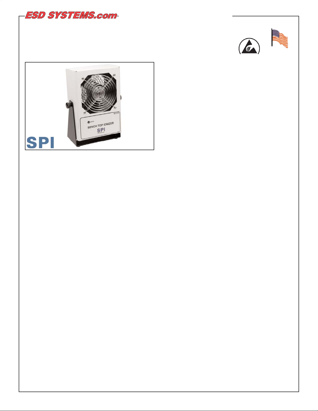
Figure 1. 94020 Bench Top Ionizer
Description
The SPI Bench Top Ionizer (SP4511) is a compact and
lightweight steady state DC auto-balancing bench top
ionizer. The unit is normally placed at one end of the
workbench or area to be neutralized. It may also be
mounted to a wall or shelf. The Ionizer's neutralization
discharge time will be best approximately 12" to 48"
directly in front of the unit and will increase as the
distance from the unit increases.
Ionizers are useful in preventing electrostatic charge
generation, ElectroStatic Discharge, ElectroStatic
Attraction, as well as preventing equipment latch-up
and safety related shock. Per ANSI/ESD S20.20
section 6.2.3.1. Protected Areas Requirement states:
"Ionization or other charge mitigating techniques shall
be used at the workstation to neutralize electrostatic
fields on all process essential insulators if the
electrostatic field is considered a threat." Air ionization
can neutralize the static charge on insulated and
isolated objects by producing separate charges in the
molecules of the gases of the surrounding air. When
an electrostatic charge is present on objects in the
work environment, it will be neutralized by attracting
opposite polarity charges from the ionized air. Note
that ionization systems should not be used as a
primary means of charge control on conductors or
people. (Reference: EN 61340-5-2:1paragraph 5.2.9)
"The primary method of static charge control is direct
connection to ground for conductors, static dissipative
materials, and personnel. Acomplete static control
program must also deal with isolated conductors that
cannot be grounded, insulating materials (e.g., most
common plastics), and moving personnel who cannot
use wrist or heel straps or ESD control flooring and
footwear.
Air ionization is not a replacement for grounding
methods. It is one component of a complete static
control program. Ionizers are used when it is not
possible to properly ground everything and as backup
to other static control methods. In clean rooms, air
ionization may be one of the few methods of static
control available." (ESD Handbook TR20.20 Ionization,
section 5.3.6.1 Introduction and Purpose / General
Information)
The SPI Bench Top Ionizer operates on DC, steady
state. Steady DC systems consist of separate negative
and positive ion emitters connected by a pair of highvoltage cables to their respective high-voltage power
supplies. The spacing between emitters varies
depending on the design, and DC power is constantly
applied to the emitter points.
Ionizer Selection
ANSI/ESD S20.20 paragraph 6.1.1.2. ESD Control
Program Plan Guidance states: "The Plan should
include a listing of the specific type of ESD protective
materials and equipment used in the Program." When
selecting an ionizer, life cycle costs should be
considered, including:
• equipment cost
•
installation cost
• operation and maintenance cost
SPI Ionizers meet the ANSI/ESD S20.20 minimum
recommended technical requirement range of less than
+/- 50 volts voltage offset tested in accordance with
ANSI-EOS/ESD S3.1. All SPI Bench Top Ionizers
greatly exceed the requirement providing ±5 to ±25 volt
auto-balancing.
Packaging
1 Bench Top Ionizer
1 Power Cord (94020 only)
1 Emitter Point Cleaner Pack
1 Certificate of Calibration
Made in America
TECHNICAL BULLETIN TB-5512
ESD Systems.com • 432 Northboro Road Central • Marlboro, MA 01752 • (508) 485-7390 • Fax (508) 480-0257 • Website: ESDSystems.com
Page 2
ESD Systems.com • 432 Northboro Road Central • Marlboro, MA 01752 • (508) 485-7390 • Fax (508) 480-0257 • Website: ESDSystems.com
© 2009 DESCO INDUSTRIES INC.
Employee Owned
TB-5512 January 2009 Page 2 of 5
Installation
Place the unit at a desired location where that the
airflow will not be restricted. Be sure that the ON/OFF
switch located on the rear of the unit is in the OFF
position. Plug the power cord into the unit and then
into the appropriate AC power source.
Operation
Air Injection Test
I. Set the fan speed switch on the rear of the unit to the
LOW, MED, or HI position (See Figure 1). Higher
airflow will result in faster neutralization rates.
II. Position the ionizer so that maximum airflow is
directed towards the items or area to be neutralized.
III. Turn the unit ON. When the unit is first turned on, it
conducts a self-test. The audible alarm will sound and
the LED will cycle through the colors red, yellow, and
green. The LED will remain green during normal
operation.
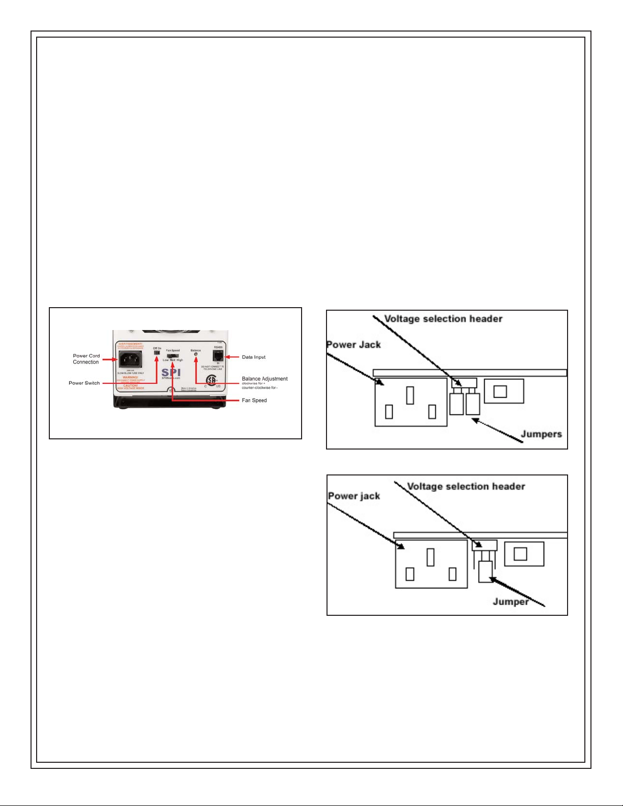
Figure 2. Rear View of the Bench Top Ionizer
Maintenance
"All ionization devices will require periodic maintenance
for proper operation." Maintenance intervals for
ionizers vary widely depending on the type of ionization
equipment and use environment. Critical clean room
uses will generally require more frequent attention. It is
important to set-up a routine schedule for ionizer
service. Routine service is typically required to meet
quality audit requirements." (ESD Handbook TR 20.20
paragraph 5.3.6.7 Maintenance / Cleaning)
EIA-625, recommends checking ionizers every 6
months, but this may not be suitable for many
programs particularly since an out-of-balance may exist
for months before it is checked again. The SPI Bench
Top Ionizer has a very desirable feature as it will
provide visual and audible alarms when an out of
balance exists. ANSI/ESD S20.20 paragraph 6.1.3.1
Compliance Verification Plan Requirement states: "Test
equipment shall be selected to make measurements of
appropriate properties of the technical requirements
that are incorporated into the ESD program plan."
Calibration AND Adjustments
Balance Adjustment
The SPI Bench Top Ionizer is an auto-balancing unit.
However, tuning or manual adjustment can be
accomplished by inserting a small screwdriver or
trimmer adjustment tool into the balance adjustment
hole located at the rear of the unit (See Figure 1). To
increase the output in a positive direction, turn the
potentiometer clockwise. To increase the output in a
negative direction, turn the potentiometer counterclockwise.
Maintenance / Alarms
WARNING - RISK OF ELECTRIC SHOCK
THESE SERVICING INSTRUCTIONS ARE FOR USE
BY QUALIFIED PERSONNEL ONLY. DO NOT
PERFORM ANY SERVICING OF INTERNAL PARTS
UNLESS YOU ARE QUALIFIED TO DO SO.
NOTE: The AC power cord MUST always be
disconnected before the unit is disassembled.
The input voltage may be verified or reset by removing
the 3 screws located on the back of the unit then
removing the back case.
The input voltage can be selected using the two
internal jumpers shown in Figures 2 and 3.
If the supply voltage drops from 110 Volts to below 85
Figure 3. 110 Volt Jumper Setting
Figure 4. 220 Volt Jumper Setting
Page 3

ESD Systems.com • 432 Northboro Road Central • Marlboro, MA 01752 • (508) 485-7390 • Fax (508) 480-0257 • Website: ESDSystems.com
© 2009 DESCO INDUSTRIES INC.
Employee Owned
TB-5512 January 2009 Page 3 of 5
Volts or from 200 Volts to below 170 Volts, the unit will
shut down, the audible alarm will beep and the LED
will blink red. The unit will automatically reset when
the minimum voltage is restored.
Cleaning the Emitter Points
Under normal conditions, the ionizer will attract dirt and
dust (especially on the emitter electrodes). To maintain
optimum neutralization efficiency and operation,
cleaning should be performed on a regular basis.
In the event of circuit failure, the unit will enter
shutdown mode.
When the unit enters shutdown mode, ionization will be
stopped, the LED on the front of the unit will illuminate
a constant red, and the audible alarm will continuously
sound. The user must then reset the unit by turning it
OFF and back ON.
The emitter points should be cleaned using the
included 94013 Emitter Point Cleaners or a swab
dampened with Isopropyl alcohol.
I. Turn the unit OFF and unplug the power cord.
II. Remove the rear screen by removing the 4 screws.
III. Clean the emitter points using the included 94013
Emitter Point Cleaners or a swab dampened with
Isopropyl alcohol
IV. Reattach the rear screen.
V. Plug in the power cord and turn the unit ON.
VI. Verify the balance of the ionizer by using a charge
plate monitor.
The emitter electrodes should not require replacement
during the life of the unit with normal handling. If
necessary, item 94014 Replacement Emitter Points are
available for order.
Specifications
The comparative efficiency of bench top ionizers is
determined by a standard test published by the ESD
Association: Standard S3.1. Typical positive and
negative decay times (1000 V - 100 V) measured using
this standard are shown below. The performance of
the ionizer was measured with the unit positioned as
shown, with the fan speed on high and without a filter.
Health
There are no known health risks associated with our
devices. The emitters work at about 4-6 kV and can
create ozone, but there have been no significant
measurement of ozone from our emitter sets as all our
existing units test well below the OSHA limit of 0.05
ppm ozone. For additional safety information, see
"Dispelling an Old Myth" written by William Metz of
Hewlett-Packard published in Evaluation Engineering
magazine September 2001.
Page 4

ESD Systems.com • 432 Northboro Road Central • Marlboro, MA 01752 • (508) 485-7390 • Fax (508) 480-0257 • Website: ESDSystems.com
© 2009 DESCO INDUSTRIES INC.
Employee Owned
TB-5512 January 2009 Page 4 of 5
Neutralization (Decay) Time Table
• Air Flow
Three speed fan (125 fpm - 250 fpm, 50 cfm -100 cfm)
• Balance
±3 Volts Typical
±5 Volts Maximum
(Temperature Range: 65oF - 80oF, Relative Humidity: 15% - 65%)
• Chassis
Powder coated aluminum housing
• Dimensions (with stand)
9.5" x 6.0" x 3.1"
• Emitter Points
.050" diameter
Made of pure tungsten for improved mechanical strength and ionization stability
• Fuse
250 mA slow blow
• High Voltage Power Supply
5.5 kV DC nominal
• Input Power
AC line power
Internally selectable for 110/115 VAC - 50/60Hz or 220/230 VAC - 50/60Hz
• Ion Emission
Steady-state DC with sense feedback
• Mounting
Bench Top tilt adjust frame
• Ozone
< 0.05 ppm
• Weight
4.5 lbs.
Page 5

ESD Systems.com • 432 Northboro Road Central • Marlboro, MA 01752 • (508) 485-7390 • Fax (508) 480-0257 • Website: ESDSystems.com
© 2009 DESCO INDUSTRIES INC.
Employee Owned
TB-5512 January 2009 Page 5 of 5
Contact and Warranty
ESD Systems
432 Northboro Road Central
Marlboro, MA 01752
Tel: (508) 485-7390
Fax: (508) 480-0257
Limited Warranty
SPI expressly warrants that for a period of one (1)
year from the date of purchase, SPI Bench Top
Ionizers will be free of defects in material (parts) and
workmanship (labor). Within the warranty period, the
product will be tested, repaired, or replaced at our
option, free of charge. Call our Customer Service
Department at 909-664-9986 for a Return Material
Authorization (RMA) and proper shipping instructions
and address. Include a copy of your original packing
slip, invoice, or other proof of purchase date. Any unit
under warranty should be shipped prepaid to the SPI
factory. Warranty repairs will take approximately two
weeks.
If your unit is out of warranty, call Customer Service at
909-664-9986 for a Return Material Authorization
(RMA) and proper shipping instructions and address.
SPI will quote repair charges necessary to bring your
unit up to factory standards.
Warranty Exclusions
THE FOREGOING EXPRESS WARRANTY IS MADE
IN LIEU OF ALL OTHER PRODUCT WARRANTIES,
EXPRESSED AND IMPLIED, INCLUDING
MERCHANTABILITY AND FITNESS FOR A
PARTICULAR PURPOSE WHICH ARE
SPECIFICALLY DISCLAIMED. The express warranty
will not apply to defects or damage due to accidents,
neglect, misuse, alterations, operator error, or failure to
properly maintain, clean or repair products.
Limit of Liability
In no event will SPI or any seller be responsible or
liable for any injury, loss or damage, direct or
consequential, arising out of the use of or the inability
to use the product. Before using, users shall
determine the suitability of the product for their
intended use, and users assume all risk and liability
whatsoever in connection therewith.
 Loading...