

TB-2039 January 2009 Page 1 of 4
TECHNICAL BULLETIN TB-2039
Operation, Installation and Calibration Instructions
N.I.S.T. Calibration Unit for Wrist S trap and Footwear Testers
DESCO WEST - 3651 Walnut Avenue, Chino, CA 91710 • (909) 627-8178 • Fax (909) 627-7449
DESCO EAST - One Colgate Way, Canton, MA02021-1407 • (781) 821-8370 • Fax (781) 575-0172 • Web Site: http://www.desco.com
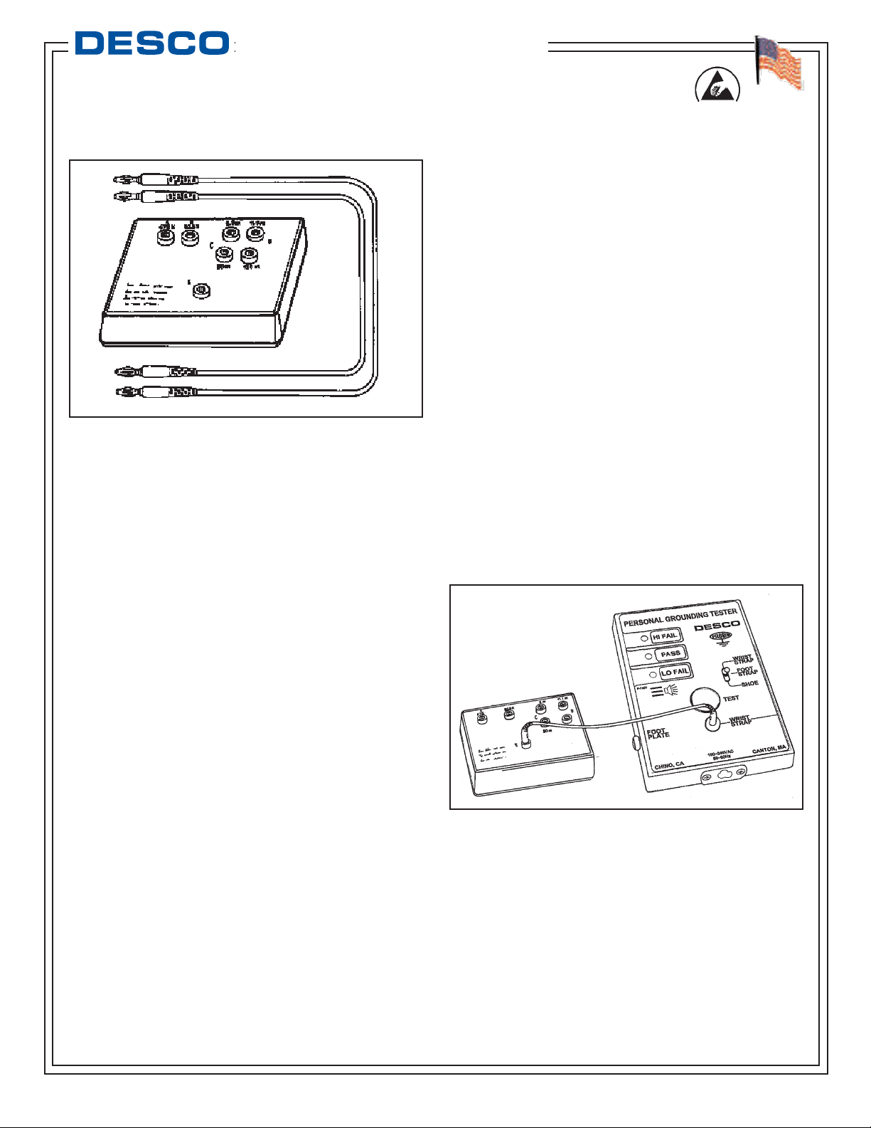
Figure 1. 07010 Calibration Unit
Description
The Desco model 07010 calibration unit is designed to
simplify the process of calibrating wrist strap and foot
ground test equipment. The calibration unit allows the
user to quickly and easily verify whether a tester is
operating within specifications. This product can be
used as one of the tools to fulfill the ANSI/ESD S20.20
paragraph 6.1.3.2 “Compliance Verification Plan”.
Verification should include routine checks of the
Technical Requirements of the Plan. Per Table 1, the
technical requirement test method for “Continuous
Monitors” is to be “per the manufacturer specifications”.
The 07010 is a passive device, and requires no power
source. The calibration unit is manufactured within
industry accepted test ranges for both wrist straps and
foot grounders. The wrist strap pass range is set at
750K - 10M, while the foot ground test range is set at
750K - 100M. The 07010 is supplied calibrated to
NIST traceable standards.
The 07010 Calibration Unit is an important tool for
optimization of an ESD control program. Aleading
corporation estimates a $95 to 1 return on every dollar
invested in ESD control. However, the ESD protective
products utilized must be working, so it is essential that
testers are in calibration that are used to verify the
parameters of wrist straps and foot grounders. The
07010 Calibration Unit easily pays for itself. Instead of
returning to Desco, a Calibration House, or even your
Metrology Department, testers can be NIST calibrated
where located in the factory being out-of-service only a
couple minutes. No need to have an extra replacement
Tester.
Remove the calibration unit from the carton and
inspect for shipping damage. Each unit should include
the following:
1 - Calibration unit, item #07010
2 - 12'' test leads
Calibration Test Procedures
The calibration unit was specifically designed for use in
calibration of Desco brand test equipment. The
following step by step procedures will cover calibration
for specific test units. The procedures will not cover
adjustment of the test equipment. For detailed
information regarding adjustment of specific Desco
brand testers contact our Customer Service
Department at 909-627-8178 (Chino, CA) or 781-8218370 (Canton, MA).
CALIBRATION OF THE MODEL 98280
WRIST STRAP TESTER
Step 1: Connect one of the test leads to common point
banana jack labeled "E" on 07010. Connect the
opposite end of test lead to 98280 tester's wrist strap
jack located on the front of the unit and switch the
selector switch to “WRIST STRAP”.
Figure 2. Connecting test lead common from 07010 to
98280.
Step 2: Connect the second test lead to the 675K jack
labeled "A" on the 07010. Touch the opposite end of
test lead to touch tester plate and press down on tester
with enough pressure to activate the test circuit.
Observe the LED's for the proper response as
indicated below. Be sure to hold the cord at an
insulated point, so that the resistance value is not
affected by the body.
Made in America
© 2009 DESCO INDUSTRIES INC.
Employee Owned
TB-2039 Page 2 of 4
DESCO WEST - 3651 Walnut Avenue, Chino, CA91710 • (909) 627-8178 • Fax (909) 627-7449
DESCO EAST - One Colgate Way, Canton, MA02021-1407 • (781) 821-8370 • Fax (781) 575-0172 • Web Site: http://www.desco.com
Resistance Value Test Output - LED
Red jack “A” - 675K: Red (Low-hazard)
Green jack “B” - 825K: Green (OK-in limits)
Green jack “C” - 8.5M: Green (OK-in limits)
Yellow jack “D” - 11.5M: Red (High resistance)
Step 3: Repeat the procedure testing across jacks B,
C, and D. The different resistance ranges should give
the display shown above. If the tester does not meet
calibration specifications, contact factory for adjustment
information, or ask for Technical Bulletin TB-3000.
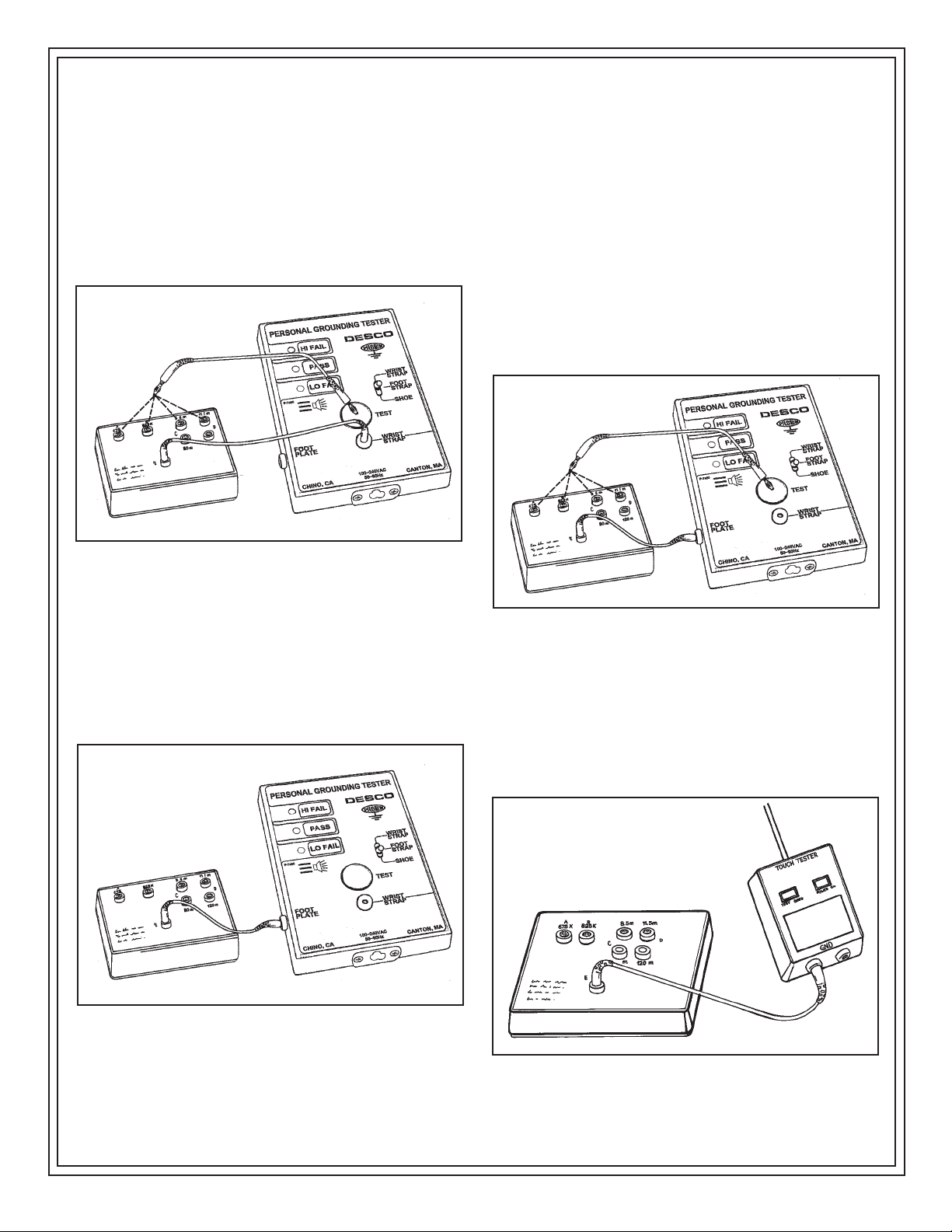
Figure 3. Testing 98280 for “PASS” and “FAIL” ranges
as indicated on calibration unit.
CALIBRATION OF THE MODEL 98280
FOOT STRAP TESTER
Step 1: Connect one of the test leads to common point
banana jack labeled "E" on 07010. Connect the
opposite end of test lead to 98280 tester's foot strap
jack located on the front of the unit and switch the
selector switch to “FOOT STRAP”.
Figure 4. Connecting test lead common from 07010 to
98280.
Step 2: Connect the second test lead to the 675K jack
labeled "A" on the 07010. Touch the opposite end of
test lead to touch tester plate and press down on tester
with enough pressure to activate the test circuit.
Observe the LED's for the proper response as
indicated below. Be sure to hold the cord at an
insulated point, so that the resistance value is not
affected by the body.
Resistance Value Test Output - LED
Red jack “A” - 675K: Red (Low-hazard)
Green jack “B” - 825K: Green (OK-in limits)
Green jack “C” - 8.5M: Green (OK-in limits)
Yellow jack “D” - 11.5M: Red (High resistance)
Step 3: Repeat the procedure testing across jacks B,
C, and D. The different resistance ranges should give
the display shown above. If the tester does not meet
calibration specifications, contact factory for adjustment
information, or ask for Technical Bulletin TB-3000.
Figure 5. Testing 98280 for “PASS” and “FAIL” ranges
as indicated on calibration unit.
CALIBRATION OF THE MODEL 19350
WRIST STRAP TESTER
Step 1: Connect one of the test leads to common
point banana jack labeled “E” on 07010. Connect the
opposite end of test lead to one of the 19350’s ground
jacks located on the front edge of the unit.
Figure 6. Connecting test lead common from 07010 to
19350.
© 2009 DESCO INDUSTRIES INC.
Employee Owned

TB-2039 Page 3 of 4
DESCO WEST - 3651 Walnut Avenue, Chino, CA91710 • (909) 627-8178 • Fax (909) 627-7449
DESCO EAST - One Colgate Way, Canton, MA02021-1407 • (781) 821-8370 • Fax (781) 575-0172 • Web Site: http://www.desco.com
Step 2: Connect the second test lead to the 675K jack
labeled “A” on the 07010. Touch the opposite end of
test lead to the test plate. Observe the LED’s for the
proper response as indicated below. Be sure to hold
the cord at an insulated point, so that the resistance
value is not affected by the body.
Resistance Value Test Output - LED
Red jack “A” - 675K: Red (Low - hazard)
Green jack “B” - 825K: Green (OK - in limits)
Green jack “C” - 8.5M: Green (OK - in limits)
Yellow jack “D” - 11.5M: Red (High resistance)
Step 3: Repeat the procedure testing across jacks B,
C, and D. The different resistance ranges should give
the display shown for the 19350. If the tester does not
meet calibration specifications, contact factory for
calibration, or ask for Technical Bulletin TB-2004.
Figure 7. Testing 19350 for “PASS” and “FAIL” ranges
as indicated on calibration unit.
CALIBRATION OF THE MODELS
19250, 19251 AND 19252
The models 19250, 19251 and 19252 testers utilize the
identical test unit. The difference between the three
models is the hardware that is included with each unit.
The model 19250 includes only the tester, model
19251 includes the tester and a metal foot plate, while
the 19252 is the tester and metal test stand assembly.
This test unit is designed with two separate test circuits
with distinct pass fail ranges. The wrist strap test
circuit incorporates a 750K - 10M pass range while the
footwear test circuit is set to pass at 750K - 100M.
Each test circuit needs to be tested individually. For
detailed information on these testers please ask for
Technical Bulletin TB-2040.
Wrist Strap Test Circuit
Step 1: Connect one of the test leads to common
point banana jack labeled “E” on 07010. Connect the
opposite end of test lead to the 19250’s wrist cord jack
located on the face of the unit.
Step 2: Connect the second test lead to the 675K jack
labeled “A” on 07010. Touch the opposite end of test
lead to tester’s test plate and press down with enough
pressure to activate the test circuit. Observe the LED’s
for the proper response as indicated below. Be sure to
hold the cord at an insulated point, so that the
resistance value is not affected by the body.
Resistance Value Test Output - LED
Red jack “A” - 675K: Red (Low - hazard)
Green jack “B” - 825K: Green (OK - in limits)
Green jack “C” - 8.5M: Green (OK - in limits)
Yellow jack “D” - 11.5M: Red (High resistance)
Step 3: Repeat the procedure testing across jacks B,
C, and D. The different resistance ranges should give
the display shown above. If the tester does not meet
calibration specifications, contact factory for calibration,
or ask for Technical Bulletin TB-2040.
Figure 8. Testing 19250 for “PASS” and “FAIL”, wrist
strap test circuit.
Footwear Test Circuit
Step 1: Connect one of the test leads to common
point banana jack labeled “E” on 07010. Connect the
opposite end of test lead to the 19250’s foot plate
ground jack located on the side of the unit.
Step 2: Connect the second test lead to the 675K jack
labeled “A” on the 07010. Touch the opposite end of
test lead to tester’s test plate and press down with
enough pressure to activate the test circuit. Observe
the LED’s for the proper response as indicated below.
Be sure to hold the cord at an insulated point, so that
the resistance value is not affected by the body.
© 2009 DESCO INDUSTRIES INC.
Employee Owned

TB-2039 Page 4 of 4
DESCO WEST - 3651 Walnut Avenue, Chino, CA91710 • (909) 627-8178 • Fax (909) 627-7449
DESCO EAST - One Colgate Way, Canton, MA02021-1407 • (781) 821-8370 • Fax (781) 575-0172 • Web Site: http://www.desco.com
Limited Warranty
Desco expressly warrants that for a period of one (1) year from
the date of purchase, Desco Calibration Units will be free of
defects in material (parts) and workmanship (labor). Within the
warranty period, the product will be tested, repaired, or replaced
at Desco’s option, free of charge. Call our Customer Service
Department at
909-627-8178
(Chino, CA) or 781- 821-8370
(Canton, MA) for a Return Material Authorization (RMA) and
proper shipping instructions and address. Include a copy of your
original packing slip, invoice, or other proof of purchase date. Any
unit under warranty should be shipped prepaid to the Desco
factory. Warranty repairs will take approximately two weeks.
If your unit is out of warranty, call Customer Service at
909-627-
8178
(Chino, CA) or 781-821-8370 (Canton, MA) for a Return
Material Authorization (RMA) and proper shipping instructions
and address. Desco will quote repair charges necessary to
bring your unit up to factory standards.
Warranty Exclusions
THE FOREGOING EXPRESS WARRANTY IS MADE IN LIEU
OF ALL OTHER PRODUCT WARRANTIES, EXPRESSED AND
IMPLIED, INCLUDING MERCHANTABILITY AND FITNESS
FOR APARTICULAR PURPOSE WHICH ARE SPECIFICALLY
DISCLAIMED. The express warranty will not apply to defects or
damage due to accidents, neglect, misuse, alterations, operator
error, or failure to properly maintain, clean or repair products.
Limit of Liability
In no event will Desco or any seller be responsible or liable for
any injury, loss or damage, direct or consequential, arising out of
the use of or the inability to use the product. Before using,
users shall determine the suitability of the product for their
intended use, and users assume all risk and liability whatsoever
in connection therewith.
Resistance Value Test Output - LED
Red jack “A” - 675K: Red (Low-hazard)
Green jack “B” - 825K: Green (OK-in limits)
Green jack “C” - 80M: Green (OK-in limits)
Yellow jack “D” - 120M: Red (High resistance)
Step 3: Repeat the procedure testing across jacks B,
C (80M), and D (120M). The different resistance
ranges should give the display shown above. If the
tester does not meet calibration specifications, contact
factory for calibration, or ask for Technical Bulletin
TB-2040.
Figure 9. Testing 19250 for “PASS” and “FAIL” ranges
for footwear circuit as indicated on calibration unit.
Specifications
Power Source: Passive device, no power source
required
Resistance Ranges -
Wrist straps: Low - 675 Kilohm
Pass - 825 Kilohm
Pass - 8.5 Megohm
High - 11.5 Megohm
Footwear: Low - 675 Kilohm
Pass - 825 Kilohm
Pass - 80 Megohm
High - 120 Megohm
Calibration: NIST traceable
Calibration Interval: Recommended annually
Accuracy: ±2%
Weight: 10 ounces
Dimensions: 4.50" x 3.25" x 1.00"
Consider adding the 07010 to your list of “test
equipment that shall be selected to make
measurements of appropriate properties of the
technical requirements that are incorporated into the
ESD program plan” as required by paragraph 6.1.3.1 of
ANSI/ESD S20.20.
© 2009 DESCO INDUSTRIES INC.
Employee Owned
 Loading...