

Page 1
Cleaning
Foot grounders are to ground static charges, while
dirt generally provides an insulative layer adversely
effecting reliability . For proper operation, the Foot
Grounder and its conductive strip must be kept clean.
The rubber portion of the Foot Grounder should be
cleaned using Desco’s Reztore™ Antist atic Surface &
Mat Cleaner or “Static-Wipes” wipers. An alternative
would be to clean using isopropyl alcohol. The Desco
cleaning products are specially formulated for
cleaning ESD control components and are silicone
free. This is critical as silicone is an insulator. Desco
ESD cleaners should not be used to clean the nylon
polyester grounding tab.
Foot Grounders can be safely hand or machine
washed on gentle cycle. Mild detergents, such as
Woolite
®
or a liquid dish washing product and warm
water are recommended. However, care must be
taken to ensure that these detergents are silicone
free.
Installation
HOOK & LOOPAND MARR RESISTANT
HEEL GROUNDERS
Desco model 07560, 17200, 17202, 17250, 17252,
and 17260 heel grounders are designed for use on
standard shoes. All Desco foot grounders can be
easily adjusted to fit the individual wearer. Desco heel
grounders have a dissipative lining that will not mar
white or light colored shoes. Models 07560, 17200,
17202, and 17252 have a current limiting one or two
megohm resistor in series with the grounding tab.
Models 17250 and have no resistor.
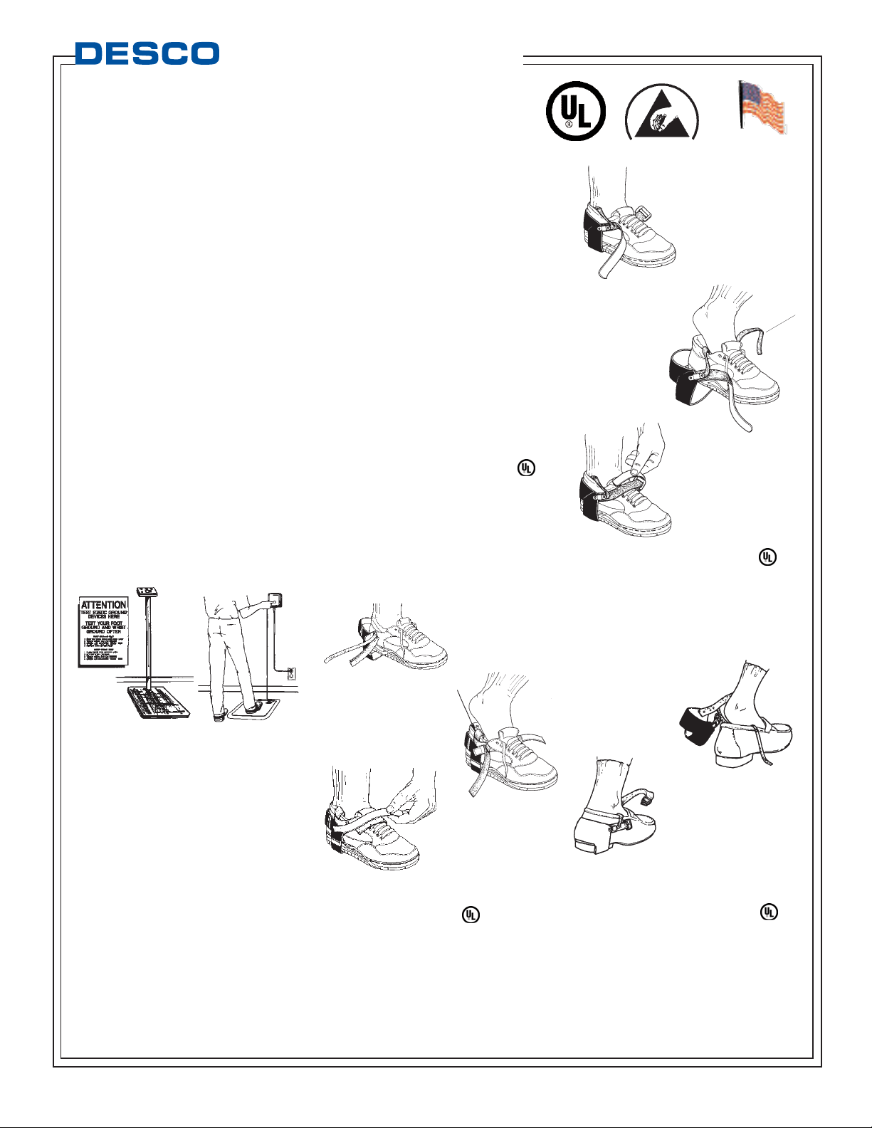
1. Place the foot grounder on
the shoe so that the lining is
making contact with the
shoe.
2. Insert the grounding
tab inside of the shoe
and under the foot.
Make sure that a solid contact
is made between the sock
and body. Cut grounding t ab
to desired length.
3. Fasten hook and loop
straps together, securing
foot grounder firmly on
shoe.
4. Test each foot
grounder to confirm proper installation.
D-RING HEEL GROUNDERS
Desco model 07590 heel grounders are equipped
with an elastic D-ring fastening system which
provides snug cinching of the ankle strap and allows
"flex" during walking. They are designed for use on
most types of shoes and boots. The light blue lining
prevents marring on white or light colored shoes.
These foot grounders include a
molded external resistor and
a permanently attached
grounding tab.
1. Place foot grounder
on the shoe so that
the blue lining is
making contact with
the shoe.
2. Insert the
grounding tab inside
of the shoe and
under the foot. Make
sure that a solid
contact is made
between the sock
and body. Cut
grounding tab to
desired length.
3. Pull the strap through
the D-ring and clinch
down for a snug,
comfortable fit.
4. Test each foot grounder
to confirm proper
installation.
HEEL GROUNDER WITH SNAP-LOC
FASTENING SYSTEM
The Desco model 07515 heel grounders are
equipped with a Snap-Loc quick release fastening
system. The model 07515 has a cup and lining
that will not mar shoes or floors. The 07515 has a
molded exterior 2 megohm resistor.
1. Insert the grounding tab inside
of the shoe and under the foot.
Make sure that a solid contact is
made between the sock
and body. Cut
grounding tab to
desired length.
2. Fit the
heel cup snugly to shoe and
connect the Snap-Loc fastener
together. Adjust elastic strap
for comfortable fit. Tuck excess
elastic strap behind itself.
3. Test each heel grounder to confirm proper
installation.
TB-2020 December 2008 Page 1 of 2
Foot Grounders - Grounding,
Testing, and Maintenance
Description
Desco’s complete line of foot grounders has been
created to provide a continuous ground path
between the operator and a properly grounded ESD
protected flooring. Foot grounders are designed for
use in applications where user mobility is required,
such as wave solder, kitting, and quality control. Per
ANSI/ESD S20.20 Paragraph 6.2.2.2, “ESD
protective flooring used with approved footwear,
may be used as an alternative to the wrist strap
system for standing operations.” Foot grounders
quickly and effectively drain the static charges which
collect on personnel during normal, everyday
activities.
General Guidelines
1. It is recommended that foot grounders be worn
on both feet, in order to assure that a continuous
path to ground is maintained.
2. Grounding tabs should be tucked inside the shoe
with as much contact area as possible to the bottom
of the stockinged foot. Foot grounders rely upon the
perspiration in the shoe to sustain electrical contact
between the conductive grounding tab and the
body.
3. Foot grounders should be used in conjunction
with floor surfaces which have a surface resistance
of less than 1 x 10E9 ohms.
4. Acurrent limiting one or two megohm resistor in
series with the grounding tab is recommended.
T esting Your Foot Grounders
The best test of your foot grounder is one that
includes all three components: the individual foot
grounder, the grounding tab and the interface
between the grounding tab and the wearer’s
sweatlayer.
Desco has testers designed to properly test foot
grounders. For more detailed information on these
testers, ask for technical bulletins TB-2040 (19252,
19253).
If you obtain a fail reading from the tester you should
stop working and clean the foot ground and
grounding tab. Retest after cleaning. If the unit still
fails, replace the foot grounder. Retest the system
before beginning work.
GROUNDING
TAB
DESCO WEST - 3651 Walnut Avenue, Chino, CA 91710 • (909) 627-8178 • Fax (909) 627-7449
DESCO EAST - One Colgate Way, Canton, MA02021-1407 • (781) 821-8370 • Fax (781) 575-0172 • Web Site: http://www.desco.com
HOOK & LOOP TOE GROUNDERS
Desco model 17222 toe grounders are
designed for use on heeled shoes. Desco
toe grounders have a lining that prevents
marring on white or light colored shoes.
Model 17222 has a current limiting one
megohm resistor in series with the
grounding tab.
TECHNICAL BULLETIN TB-2020
19252 19253
GROUNDING
TAB
Made in America
90P1
LISTED
© 2008 DESCO INDUSTRIES INC.
Employee Owned
Page 2
1. Insert the grounding tab inside
of the shoe and under the foot.
Make sure that
a solid contact
is made
between the
sock and body.
Cut grounding
tab to desired
length.
2. Place rubber toe
material under toe area
of shoe sole. Pull velcro
strap over top of shoe
and cinch down until
snug. Install so that the
lined surface is making
contact with the shoe.
3. Pull elastic strap around the
back of the heel. Adjust Dring plastic loop for a
comfortable fit.
4. Test each toe
grounder to confirm
proper installation.
TB-2020 Page 2 of 2
into the shoe.
4. Test each foot
grounder on an ESD
footwear tester to
confirm proper
installation.
DISPOSABLE FOOT
GROUNDERS
SOLE GROUNDERS
Desco model 07501, 07502, and 07503 sole
grounders are designed for use on standard
shoes. Desco sole grounders are available in
three sizes and can be easily adjusted to fit the
individual wearer. Sole grounders have a lining
that prevents marring on white or light colored
shoes. Models 07507, 07508, and 07509 also
have a non-marring exterior to prevent marks on
floors. Sole grounders have a molded exterior 2
megohm resistor.
1. Place the sole grounder on the shoe so that the
GROUNDING
TAB
D-RING TOE GROUNDERS
Desco model 07595 toe grounders with the elastic
D-ring fastening system are designed for use on
heeled shoes. Desco toe grounders have a blue
lining that will prevent marring on white or light
colored shoes. These toe grounders include a
molded external 2 megohm resistor and a
permanently attached grounding tab.
Limited Warranty
Desco expressly warrants that for a period of one (1)
year from the date of purchase, Desco foot grounders
will be free of defects in material (parts) and
workmanship (labor). Within the warranty period, the
product will be tested, repaired, or replaced at
Desco’s option, free of charge. Call our Customer
Service Department at 909-627-8178 (Chino, CA) or
781- 821-8370 (Canton, MA) for a Return Material
Authorization (RMA) and proper shipping instructions
and address. Include a copy of your original packing
slip, invoice, or other proof of purchase date. Any unit
under warranty should be shipped prepaid to the
Desco factory. W arranty rep airs will take
approximately two weeks.
If your unit is out of warranty call Customer Service at
909-627-8178 (Chino, CA) or 781-821-8370 (Canton,
MA) for a Return Material Authorization (RMA) and
proper shipping instructions and address. Ship your
unit freight prepaid. Desco will quote repair charges
necessary to bring your unit up to factory standards.
Warranty Exclusions
THE FOREGOING EXPRESS WARRANTYIS
MADE IN LIEU OF ALLOTHER PRODUCT
WARRANTIES, EXPRESSED AND IMPLIED,
INCLUDING MERCHANTABILITYAND FITNESS
FOR APARTICULAR PURPOSE WHICH ARE
SPECIFICALLYDISCLAIMED. The express
warranty will not apply to defects or damage due to
accidents, neglect, misuse, alterations, operator error,
or failure to properly maintain, clean or repair
products.
Limit of Liability
In no event will Desco or any seller be responsible or
liable for any injury, loss or damage, direct or
consequential, arising out of the use of or the inability
to use the product. Before using, users shall
determine the suitability of the product for their
intended use, and users assume all risk and liability
whatsoever in connection therewith.
DESCO WEST - 3651 Walnut Avenue, Chino, CA 91710 • (909) 627-8178 • Fax (909) 627-7449
DESCO EAST - One Colgate Way, Canton, MA02021-1407 • (781) 821-8370 • Fax (781) 575-0172 • Web Site: http://www.desco.com
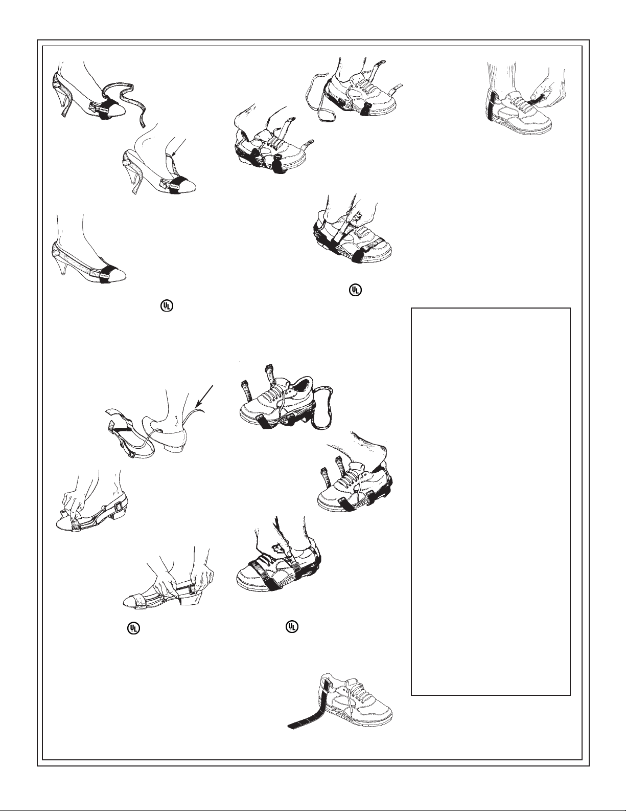
1. Place the toe grounder on
the shoe so that the
lining is making
contact with the
shoe.
2. Insert the grounding tab inside of the
shoe and under the
foot. Make sure that
a solid contact is
made between the
sock and body. Cut
grounding tab to
desired length.
3. Pull fabric strap through cam and
lock in place. This will secure toe
grounder firmly on shoe.
4.T est each toe ground to
confirm proper installation.
GROUNDING
TAB
ATTENTION: This product is not recommended for use
on equipment with operating voltage exceeding 250
VAC.
CAUTION: The ESD Series is for electrostatic control. It
will not reduce or increase your risk of receiving electric
shock when using or working on electrical equipment.
Follow the same precautions you would use without
wrist straps, including:
• Make certain that equipment having a grounding
type plug is properly grounded.
• Make certain that you are not in contact with
grounded objects other than through the ESD Series.
lining is making contact with
the shoe.
2.
Insert the grounding tab
inside of the shoe and
under the foot. Make
sure that a solid contact
is made between the sock
and body. Cut grounding t ab
to desired length.
3. Pull the strap through the
D-rings and cinch down
for a snug, comfortable
fit.
4. Test each foot
grounder to confirm proper
installation.
FULL COVERAGE GROUNDERS
Desco model 17290, 17291, and 17292 full
coverage grounders are designed for use on
standard shoes. They can be easily adjusted to fit
the individual wearer. They have a lining that will
not marr most footwear. These foot grounders
have a discrete one megohm resistor built into the
grounding tab.
1. Place the full
coverage
grounder on the
shoe so that the
lining is making
contact with the
shoe.
2. Insert the grounding
tab inside of the shoe
and under the foot. Make
sure that solid contact is
made between the
stockinged foot and
grounding tab. Cut
grounding tab to desired
length.
3. Connect the snap-
loc fastener together.
Adjust elastic strap for
comfortable fit. Tuck
excess elastic strap
behind itself.
4. Test each full
coverage grounder to confirm proper installation.
FULL COVERAGE NON-MARRING
GROUNDERS
1. Insert the conductive grounding tab inside the
shoe and under the foot.
2. Pull front and side extension tabs securing Full
Coverage Foot Grounder
around the periphery of
shoe positioning straps
near heel and ball of foot.
3. Then, tuck excess
conductive
grounding tab
© 2008 DESCO INDUSTRIES INC.
Employee Owned
 Loading...