

Page 1
TECHNICAL BULLETIN TB-3034
Combo Tester X
3
Installation, Operation and Maintenance
Per ANSI/ESD S1.1 section 6.1.3 Frequency of Functional Testing
“The wrist strap system should be tested daily to ensure proper
electrical value.”
Per ESD Handbook ESD TR20.20 section 5.3.2.4.2 Additional
User Wrist Strap Testing “Proper testing of the wrist strap includes
the resistance of the groundable point on the end of the cord,
the cord itself, the resistor, the cord-to cuff snap connector, the
resistance of the interface of the cuff, the cuff/wrist interface, and
the resistance of the person between the wrist and the hand that
contacts the test electrode.”
Per ESD Handbook ESD TR20.20 section 5.3.2.2.2 Wrist Strap
Ground Cord “At first glance, the ground cord appears to be a
relatively simple assembly. However, the design requirements are
considerable, given the wide range of user applications and the
durability requirements of constant tugging, flexing, and dragging
over the edge of workstation tops and equipment chassis.”
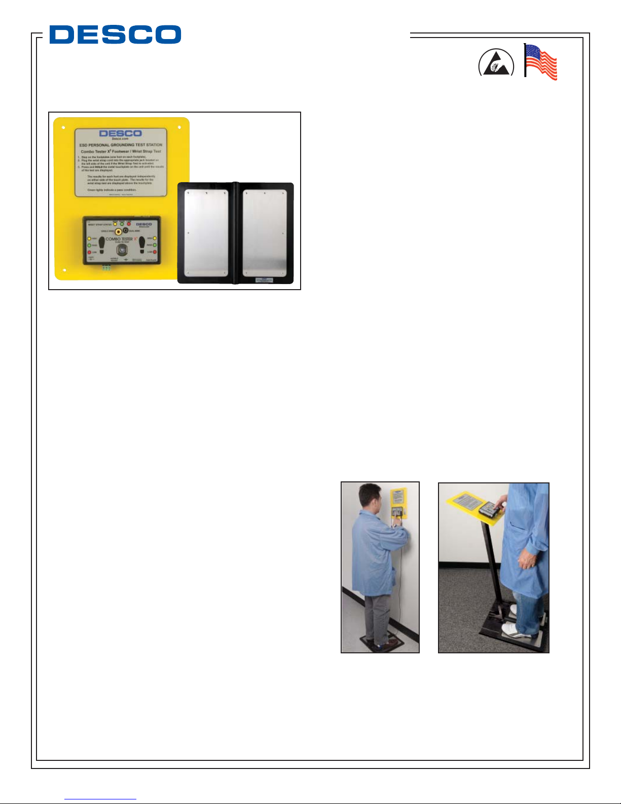
Figure 1. Desco Combo Tester X3 and Dual Foot Plate
Description
The Desco 19276/19277 Combo Tester X3 simultaneously tests
an operator’s wrist strap and footwear to determine that the wrist
strap and/or foot wear will act as a path to ground; and it tests the
presence of an inline 1 Megohm resistor. This product can be
used as one of the tools to fulfill the ANSI ESD S20.20 paragraph
6.1.3.2 “Compliance Verification Plan. Verification should include
routine checks of the Technical Requirements of the Plan.” The
Combo Tester X3 incorporates a test circuit design that allows
operators to test their wrist strap and foot wear simultaneously
and eliminates the need to conduct separate tests. The Combo
Tester X3 is factory set to 750 kilohm - 10 megohm for wrist
straps and to 750 kilohm - 100 megohm for footwear. The Combo
Tester X3 can be tailored to other ESD Control Plan requirements
with DIP switches. A green light signals the operator that the
wrist strap and footwear is passing. A red light and an audible
alarm will indicate if the wrist strap and/or footwear (left or right)
is failing. If there is a failure It will also notify the operator if the
circuit resistance is too low or too high. The Combo Tester X3 is
calibrated to NIST traceable standards.
“Compliance verification should be performed prior to each
use (daily, shift change, etc.). The accumulation of insulative
materials may increase the foot grounder system resistance. If
foot grounders are worn outside the ESD protected area testing
for functionality before reentry to the ESD protected area should
be considered.” (ESD SP9.2 APPENDIX B - Foot Grounder Usage
Guidance)
“A log should be maintained which verifies that personnel have
tested their personal grounding devices. (Wrist Straps and
ESD Footwear)” (ANSI/ESD S20.20 Section 6.2.2.2 Personnel
Grounding Guidance)
Made in America
Features
• Stainless Steal Split Foot Plate for Testing Foot Grounders
(or Shoes)
• Solid State Touch Test Button With No Moving Parts
• 30 Volt Test Signal
• Relay For Use With Automatic Doors Or Other Locking Systems
• CAT5 Connector For Data Output
Per ANSI/ESD S20.20 section 7.3 “A Compliance Verification Plan
shall be established to ensure the Organization’s fulfillment of the
technical requirements of the ESD Control Program Plan. Process
monitoring (measurements) shall be conducted in accordance
with a Compliance Verification Plan that identifies the technical
requirements to be verified, the measurement limits and the
frequency at which those verifications shall occur. The Compliance
Verification Plan shall document the test methods and equipment
used for process monitoring and measurements. … The test
equipment selected shall be capable of making the measurements
defined in the Compliance Verification Plan.”
DESCO WEST - 3651 Walnut Avenue, Chino, CA 91710 • (909) 627-8178 • Fax (909) 627-7449
DESCO EAST - One Colgate Way, Canton, MA 02021-1407 • (781) 821-8370 • Fax (781) 575-0172 • Website: Desco.com
TB-3034 June 2009 Page 1 of 5
Desco Combo
Tester X3 with Dual
Plate, Item 19276
Desco Combo Tester
X3 with Stand,
Item 19277
© 2009 DESCO INDUSTRIES INC.
Employee Owned
Page 2
Packaging
1 Combo Tester X3
1 Dual Foot Plate
1 Power Adapter - Universal Input (with US style plug)
1 Stereo Plug to Stereo Plug Cord
1 Banana Plug to Ring Terminal Cord
1 19255 Dual Foot Plate Stand (19277 only)
2 Pedestal Bolts (19277 only)
2 Nuts for Pedestal Bolts (19277 only)
2 Tester Backplate Screws (19277 only)
2 Nuts for Backplate Screws (19277 only)
4 Footplate Screws (19277 only)
1 Certificate of Calibration
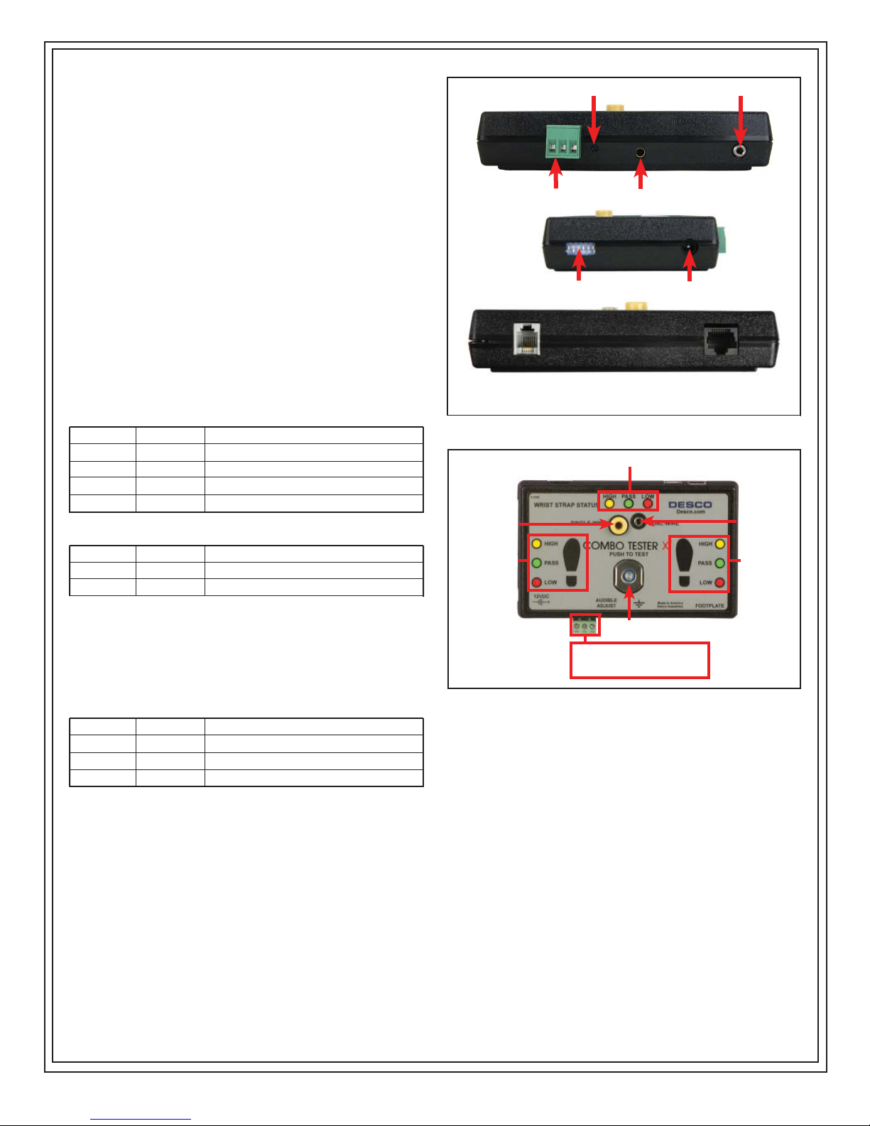
SIDE VIEW
Audio Adjustment
Relay
Ground Jack
Foot Plate Jack
FRONT VIEW
Installation
The resistance limits for footwear and wrist strap tests are
controlled by the DIP switches located on the left-side of the tester
(see Figure 2). See the following tables for the DIP switch settings
and their corresponding test values.
FOOTWEAR RESISTANCE
DIP switches 1 and 2 control the “HIGH” test limit
Switch 1 Switch 2 HIGH Limit Resistance
ON ON 10 Megohms (1 X 10E7)
OFF OFF 35 Megohms (3.5 X 10E7)
ON OFF 100 Megohms (1 X 10E8)
OFF ON 1 Gigohms†
DIP switches 3 and 4 control the “LOW” test limit
Switch 3 Switch 4 Low Limit Resistance
ON OFF 100 Kilohms (1 X 10E5)
OFF ON 750 Kilohms (7.5 X 10E5)
† NOTE: At 1 Gigohm high limit resistance, a dirty foot plate
could result in a false pass. Be sure to keep the foot plate clean,
particularly when using this setting. Not suitable for relative
humidity greater than 50%.
WRIST STRAP RESISTANCE
DIP switches 5 and 6 control the “HIGH” test limit
Switch 5 Switch 6 HIGH Limit Resistance
OFF OFF Wrist Strap Test Disabled
ON OFF 35 Megohms (3.5 X 10E7)
ON ON 10 Megohms (1 X 10E7)
DIP switch 5 must be ON (default setting) for the wrist strap test to
be active. If the wrist strap test is disabled by DIP switch 5 being
OFF, the 3 LEDs for this test will remain OFF at all times.
The “Low” limit for the wrist strap test is set to 750 Kilohms and
cannot be changed by the user
DIP Switch
Power Jack
TOP VIEW
Figure 2. Combo Tester X3 views
Wrist Strap
Single Wire Jack
Left Foot
Test Contact
1 2 3 1 & 2 = Normally closed
Relay 2 & 3 = Normally open
1 A @ 30 VDC (Rating)
Dual-Wire Jack
Right Foot
Figure 3. Combo Tester X3 panel
INSTALLING THE MODEL 19276 TESTER
I. Mount the Tester at the desired location using the four
mounting holes in the corners of the yellow mounting
plate.
II. Set the Dual Foot Plate below the tester.
III. Insert one end of the Stereo Plug to Stereo Plug cord
into the stereo jack located at the bottom of the tester
(see Figure 2). Insert the other end of the cord into the
stereo jack at the back of the foot plate.
DESCO EAST - One Colgate Way, Canton, MA 02021-1407 • (781) 821-8370 • Fax (781) 575-0172 • Website: Desco.com
DESCO WEST - 3651 Walnut Avenue, Chino, CA 91710 • (909) 627-8178 • Fax (909) 627-7449
TB-3034 Page 2 of 5
IV. Insert the banana plug end of the Banana Plug to Ring
Terminal cord into the ground jack located at the bottom
of the tester (see Figure 2). Connect the ring terminal
end of the cord to equipment ground. This connection
will remove any static charge from the user before the
test. NOTE: Failure to correctly ground the tester
may result in damage not covered under warranty.
© 2009 DESCO INDUSTRIES INC.
Employee Owned
Page 3
V. Insert the power supply plug into the power jack located
on the left-side of the tester (see Figure 2). Plug the
power supply into an appropriate power outlet.
ASSEMBLING THE MODEL 19277 TESTER
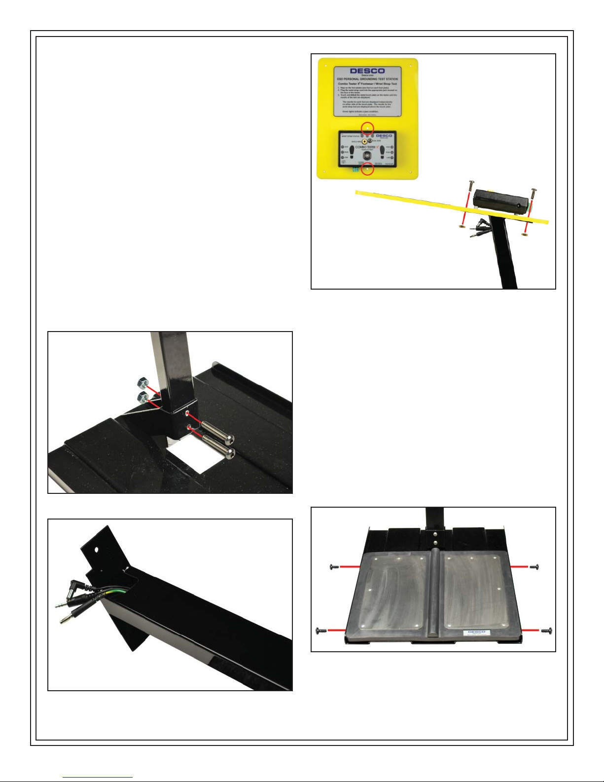
I. Insert the pedestal to the baseplate with the tester
mounting bracket sloping towards the operator. Be
sure to align the screw holes located at the base of the
pedestal.
II. Install the two supplied socket cap screws and nuts
(see Figure 4).
III. Route the two included cords and power cord through
the pedestal starting from the bottom to the top. All
three cords should exit through the cut-out located at
the top of the pedestal (see Figure 5).
IV. Align the two screw holes of the yellow backplate to the
screw holes on the pedestal mounting bracket. Secure
the backplate using the supplied screws and nuts (see
Figure 6).
V. Insert one end of the Stereo Plug to Stereo Plug cord
into the stereo jack located at the bottom of the tester
(see Figure 2). Insert the other end of the cord into the
stereo jack at the back of the foot plate.
Figure 6. Securing the Combo Tester X3 to the pedestal
VI. Insert the banana plug end of the Banana Plug to Ring
Terminal cord into the ground jack located at the bottom
of the tester (see Figure 2). Connect the ring terminal
end of the cord to earth ground. This connection will
remove any static charge from the user before the test.
NOTE: Failure to correctly ground the tester may
result in damage not covered under warranty.
Figure 4. Securing the pedestal to the baseplate
VII. Insert the power supply plug into the power jack located
on the left-side of the tester (see Figure 2).
VIII. Fit the the foot plate into position so that it is flush with
the front and top of the baseplate. Secure the foot
plate to the sides of the baseplate using the four
supplied screws (see Figure 7).
IX. Plug the power supply into an appropriate power outlet.
Figure 7. Securing the foot plate to the baseplate
Figure 5. Routing the cords through the pedestal
DESCO WEST - 3651 Walnut Avenue, Chino, CA 91710 • (909) 627-8178 • Fax (909) 627-7449
DESCO EAST - One Colgate Way, Canton, MA 02021-1407 • (781) 821-8370 • Fax (781) 575-0172 • Website: Desco.com
TB-3034 Page 3 of 5
© 2009 DESCO INDUSTRIES INC.
Employee Owned
Page 4
RELAY TERMINAL
A relay with both “normally open” and “normally closed” contacts
is included for your convenience. Going from left to right, the
terminal block on the bottom of the tester has terminals for
“normally closed,” “common,” and “normally open” (see Figure
3). The relay can be used for opening an electric lock to an ESD
protective area. The maximum contact rating is: 1A@30VDC.
General Instructions
In the following test configurations, the 19276/19277 Combo
Tester X3 can be used to test wrist straps and foot wear. NOTE:
When testing or calibrating, press and hold for test results, then
allow 1-2 seconds for the unit to reset before pressing the test
button again.
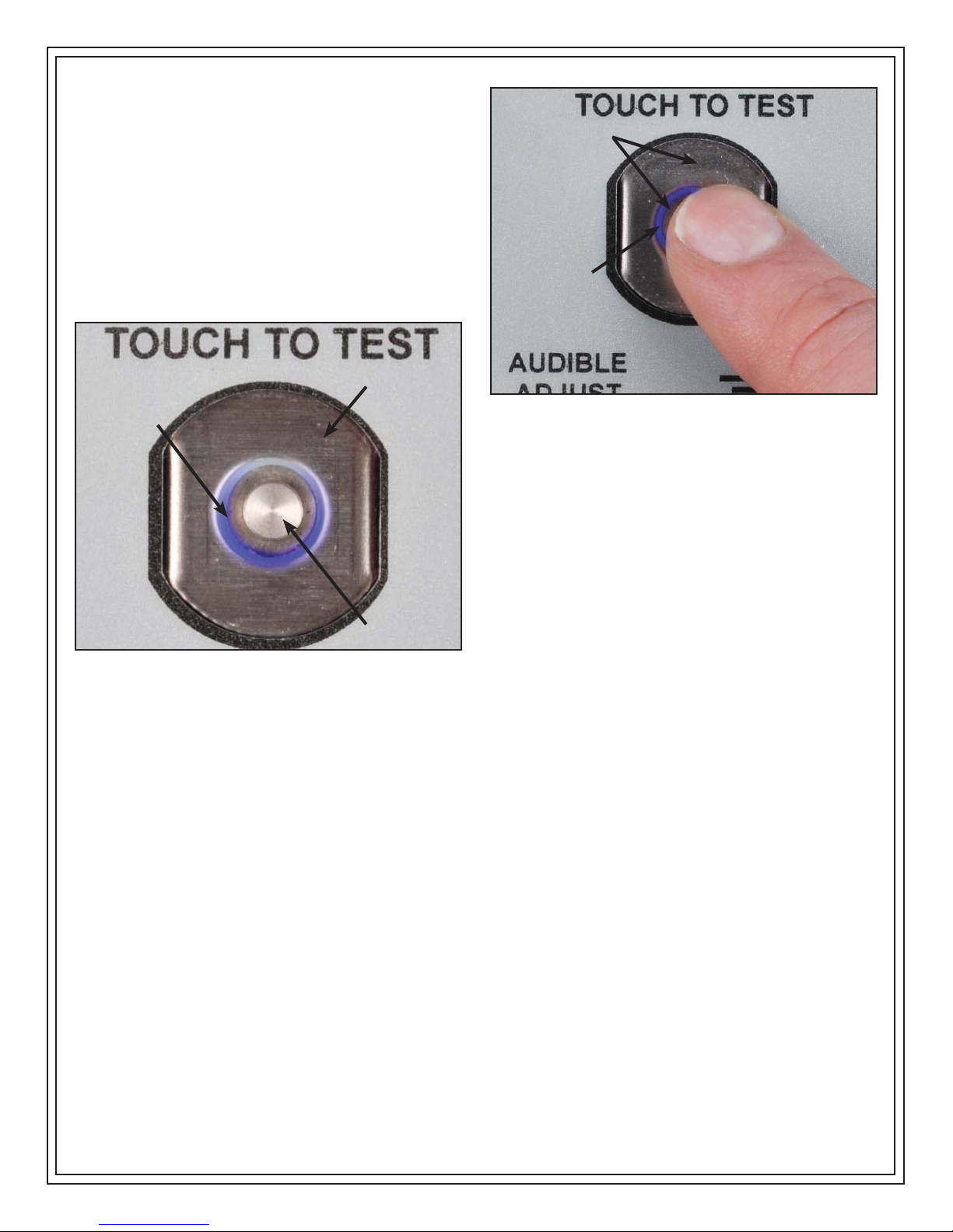
FINGER MUST BRIDGE
BOTH INNER &
OUTER CONTACT
POINTS
SOLID LED
WILL INDICATE
TEST IN PROGRESS
CIRCLING LED
INDICATES
OUTER
CONTACT
THAT TESTER
IS READY
FOR USE
INNER
CONTACT
Figure 8. Test Contact
I. A circling blue light between the inner and outer contacts will
indicate that the tester is ready for use. (See Figure 8)
II. While wearing the wrist strap and foot wear*, plug the banana
plug end of the cord into the jack (both single wire and dual
wire wrist straps can be tested with the Combo Tester X3,
make sure the correct jack is used. See Figure 3) on the
face of the unit and step on to the test plate so that one foot
is on each test plate. NOTE: DO NOT TOUCH ANY OTHER
METAL WHILE PERFORMING TEST.
III. To start the test, the operator’s finger must bridge both the
inner and outer contacts when touching the test contact. The
circling blue light will become solid to indicate that a test has
been activated. Hold down for up to 3 seconds while flexing
coil cord area near resistor. (See Figure 9) NOTE: Often the
initial intermittency will be failure of strain relief connection
to resistor as simulated by ESD S1.1-1998 paragraph 5.7
Bending Life Test.
Figure 9. Bridge test contacts with finger
V. If either “FAIL LO” or “FAIL HI” LEDs light and the audible
indicator sounds, the wrist strap and/or foot wear should
be checked to see if they functioning properly, being worn
correctly, and/or need to be replaced. NOTE: Failures may
be caused by dry skin or minimal sweat layer. For wrist
straps, try using ESD hand lotion for a better connection and
for foot wear, try taking a short walk to build up a sweat layer
in the operator’s shoe.
*The Combo Tester X3 may also be used to test smocks or
garments that feature a grounding mechanism for operators using
a coil cord connection.
Specifications
Rated tester voltage:
12 VDC, (2.5 mm connector - center positive)
Relay contact rating:
1 A @ 30 VDC max
Temperature range:
41°F - 104°F (5°C - 40°C)
Operating conditions:
Indoor use only at altitudes less than 6500 ft. (2 km).
Maximum relative humidity of 80% up to 88°F (31°C) decreasing
linearly to 50% @ 104°F (40°C).
Maximum relative humidity of 50% at 1 Gigohm setting.
Pollution degree:
2 per IEC 644
IV. Lighting of the green “PASS” LEDs indicates that the wrist
strap and/or foot wear are being worn correctly and functioning
properly.
DESCO WEST - 3651 Walnut Avenue, Chino, CA 91710 • (909) 627-8178 • Fax (909) 627-7449
DESCO EAST - One Colgate Way, Canton, MA 02021-1407 • (781) 821-8370 • Fax (781) 575-0172 • Website: Desco.com
TB-3034 Page 4 of 5
© 2009 DESCO INDUSTRIES INC.
Employee Owned
Page 5
Calibration
The Combo Tester X3 is calibrated to standards traceable to
NIST. Frequency of recalibratrion should be based on the critical
nature of those ESD sensitive items handled and the risk of failure
for the ESD protective equipment and materials. In general, we
recommend that calibration be performed annually.
The accuracy of the Combo Tester X3 is specified as:
• ±5% for < 1 Megohm range
• ±10% for 1 Megohm and higher resistance ranges
A periodic check (once every 6 to 12 months) using a precision
resistance box should be performed to verify proper operation.
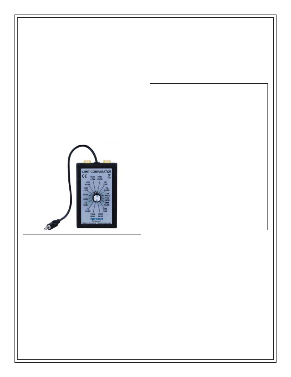
The Desco 19254 Limit Comparator is available for the convenient
period testing of the Combo Tester X3 (see figure 8).
The Limit Comparator allows the customer to perform NIST
traceable calibration on the Combo Tester X3. The Limit
Comparator can be used on the floor shop within a few minutes
virtually eliminating downtime, verifiying that the Combo Tester X3
is operating within tolerances.
V. Select either the “10M PASS” or “35M PASS” setting,
whichever one is appropiate, on the Limit Comparator and
repeat the test. The tester should indicate a wrsit strap PASS
condition.
VI. Select either the “10M HIGH” or “35M HIGH” setting,
whichever one is appropiate. on the Limit Comparator and
repeat the test. The tester should indicate a wrist strap FAIL
HIGH condition.
Limited Warranty
Desco expressly warrants that for a period of one (1) year from the date
of purchase, Desco Combo Tester X3‘s will be free of defects in material
(parts) and workmanship (labor). Within the warranty period, the product
will be tested, repaired, or replaced at Desco’s option, free of charge.
Call our Customer Service Department at
781- 821-8370 (Canton, MA) for a Return Material Authorization (RMA)
and proper shipping instructions and address. Include a copy of your
original packing slip, invoice, or other proof of purchase date. Any unit
under warranty should be shipped prepaid to the Desco factory. Warranty
repairs will take approximately two weeks.
If your unit is out of warranty, call Customer Service at
(Chino, CA) or 781-821-8370 (Canton, MA) for a Return Material
Authorization (RMA) and proper shipping instructions and address.
Desco will quote repair charges necessary to bring your unit up to
factory standards.
909-627-8178
(Chino, CA) or
909-627-8178
Warranty Exclusions
THE FOREGOING EXPRESS WARRANTY IS MADE IN LIEU OF
ALL OTHER PRODUCT WARRANTIES, EXPRESSED AND IMPLIED,
INCLUDING MERCHANTABILITY AND FITNESS FOR A PARTICULAR
PURPOSE WHICH ARE SPECIFICALLY DISCLAIMED. The express
warranty will not apply to defects or damage due to accidents, neglect,
misuse, alterations, operator error, or failure to properly maintain, clean
or repair products.
Figure 8. Limit Comparator
USING THE LIMIT COMPARATOR
Wrist Strap Operation Test
I. Insert the Limit Comparator’s test plug into the “DUAL-WIRE”
phono jack located on the face of the Combo Tester X3.
II. Select “750K LOW” with the Limit Comparator’s rotary switch.
III. Press and hold the touch plate of the tester until the test is
completed. The tester should indicate a wrist strap FAIL LOW
condition.
IV. Select “750K PASS” on the Limit Comparator and repeat the
test. The tester should indicate a wrist strap PASS condition.
Limit of Liability
In no event will Desco or any seller be responsible or liable for any
injury, loss or damage, direct or consequential, arising out of the use of
or the inability to use the product. Before using, users shall determine
the suitability of the product for their intended use, and users assume all
risk and liability whatsoever in connection therewith.
DESCO EAST - One Colgate Way, Canton, MA 02021-1407 • (781) 821-8370 • Fax (781) 575-0172 • Website: Desco.com
DESCO WEST - 3651 Walnut Avenue, Chino, CA 91710 • (909) 627-8178 • Fax (909) 627-7449
TB-3034 Page 5 of 5
© 2009 DESCO INDUSTRIES INC.
Employee Owned
 Loading...