

Ground Gard 5
TECHNICAL BULLETIN TB-5537
Operation, Installation, and Maintenance
Packaging
Item 94393
1 Ground Gard 5 Monitor
2 Remote Operator Module
1 Power Adapter
2 Remote Operator Cables
1 Mat Ground Cord
1 Push and Clinch Snap
94340
94393
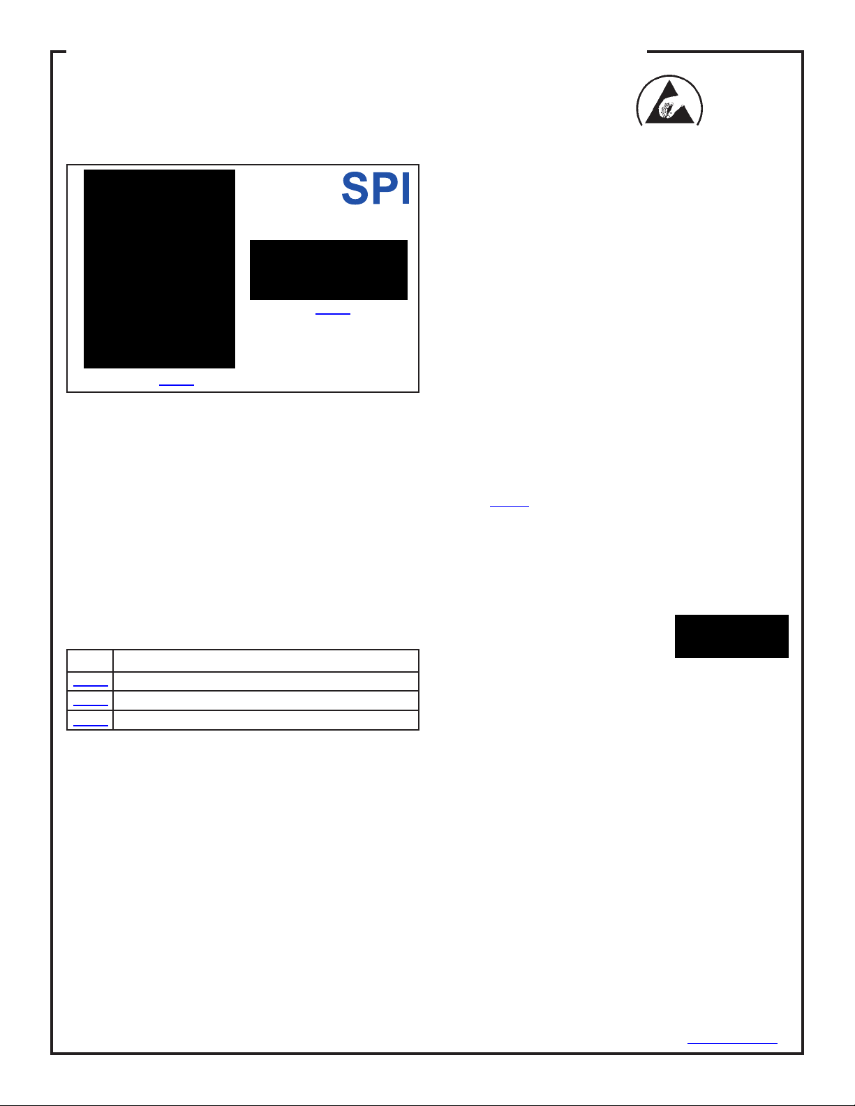
Figure 1. SPI Ground Gard 5
Description
The Ground Gard 5 is a wrist strap and ground monitoring device for the electronics workstation. When
used correctly, it will provide a static safe and properly
grounded work environment. It is designed to constantly
monitor two capacitance type single wire wrist straps
using a remote module for each user. A Ground Sense
circuit with looping capability is also provided to
constantly monitor the ground condition of bench tops,
mats, wrist straps and the Ground Gard 5 unit itself.
The Ground Gard 5 is available in the following model.
the part numbers are listed below:
Item Description
94393 Ground Gard 5 with Buzzer
94332 Power Supply, 12 Volt, 3 Prong (for use with 94393)
94340 Remote Operator Module, Under Bench
2 Velcro® Strips
4 Screws
1 Certicate of Calibration
Installation:
1. GROUND GARD 5 MONITOR:
The Ground Gard 5 Monitor is designed to not reduce
valuable work area and should be mounted at eye level
above the workstation, either on a post or shelf support.
A double-sided adhesive Velcro attachment is provided
to hold the lightweight head in place.
2. GROUND CONNECTION:
For item 94393 the ground connection is made through
the third prong of the 3-conductor power supply.
Caution: The total amount of resistance through all
monitored parts should not exceed 10.0 megohms total.
3. REMOTE OPERATOR MODULES:
The remote operator module can be mounted at the front
of the work surface, usually under the
tabletop and ush with the front edge.
Two screws for each unit are provided
for mounting. Connect each remote to
the monitor unit using the telephone cable with RJ11
connectors.
4. POWER UP TEST:
After installing the Monitor, remote units, and making the
necessary connections without the wrist straps
connected, the unit should POWER UP with the ground
sense LED indicator GREEN, the wrist strap LED’s OFF
and the audible alarm SILENT. If you have no response
to power or a red LED, check AC outlet for proper ground
or refer to trouble-shooting section.
Made in America
The Ground Gard 5 will alarm if preset values are
exceeded forcapacitance, high resist and ground loss
conditions. The grounding system is redundant and will
still provide a limited grounding even if the utility ground
is lost and the system is in an alarm state.
ESD Systems.com • 432 Northboro Road Central • Marlboro, MA 01752 • (508) 485-7390 • Fax (508) 480-0257 • Website: ESDSystems.com
TB-5545 Page 1 of 4 Revision May 2009
TB-5537 September 2010 Page 1 of 3
© 2009 DESCO INDUSTRIES INC.
Employee Owned
ESD Systems.com • 432 Northboro Road Central • Marlboro, MA 01752 • (508) 485-7390 • Fax (508) 480-0257 • Website: ESDSystems.com
© 2010 DESCO INDUSTRIES INC.
Employee Owned

PARK SNAP
The audible alarm is designed to alert both operator and
supervisor. The Park Snap feature provides a means
for an operator to disconnect when normally leaving the
work area, without the audible alarm sounding, and it
provides a means of wrist cord storage (visual red LED
will illuminate). You may also disconnect coil cord by
unplugging banana plug from the remote.
Remote Module Description:
Inside the remote module is an infrared sensor that
reacts to the insertion of a wrist strap wire with a banana
plug. When the banana plug is inserted, the base unit is
activated for that remote module. The monitor LED for
the left or right wrist strap will light showing the condition
of that strap. If correct, the LED should be GREEN.
Should the wrist strap fail, be worn incorrectly, or
removed by the operator, the red indicator will ash,
calling attention to a problem. Should the ground
connection be lost, the red light and alarm will be
activated. The monitor is continuous and even a
momentary break will cause alarms. The remote module
is set at the factory to allow for sensitivity of the
“average” human body model.
Calibration Procedures Using
Model 94370
With coils wires connected to test unit and each remote,
observe the following. Both lights should illuminate green
on the monitor, with no buttons depressed on the tester.
Pressing button one or four should cause the left or right
wrist strap togo red, simulating a high resist condition on
the wrist strap. This shows the wrist remote is properly
calibrated.
If the above conditions are not met, make the following
adjustment:
With buttons one and four not depressed, the LED
display on the monitor should be in a green condition. If
not, nd the adjusting port on the remote. Inside there is
an adjusting trim pot. Turn the trim pot slightly until the
head module LED turns green.
Step One: Turn the pot until the green LED triggers red,
then ease back until LED triggers green.
Step Two: Press the corresponding button on the test
unit and the LED will go red on the monitor. This shows
the Ground Gard 5 remote is in a proper calibration.
Note: If the unit does not go red, go back to step one
and repeat procedure.
Installation Adjustments:
Should your system alarm without obvious cause, rst
troubleshoot and verify all connections. If all the
connections are correct, the base unit should be
adjusted to compensate for a different HBM (human
body model). We preset the units at the factory at 100pF
and your operator might be out of the tolerance range
caused either by body chemistry, bulk capacitance or
impedance differences.
Follow these steps to adjust and personalize the base
unit:
Locate the small hole in the face of the remote module
(factory adjustment label may cover hole). Inside this
hole is a trim pot device that is adjustable by using a
small at-head screwdriver.
With the system set up and operating, and the operator’s
wrist strap connected to the remote module:
1. Turn the pot until the green light activates. Disconnect
the wrist wire from the band. The unit should alarm and
activate the red light. If not, turn the trim pot until the
red light activates. Reconnect the wire to the wrist band
and the alarm should cease and the green light should
activate.
2. Turn the pot until the green light begins. Disconnect
the wrist wire from the band. The unit will alarm and
activate the red light. If not, turn the trim pot until the red
light activates. Reconnect the wire to the wristband and
the alarm will cease, the green light will activate.
GROUND SENSE OR TABLE TOP MONITORING:
The Ground Gard 5 includes a ground monitoring system
that assures a positive ground connection for the
workstation. The resistance range is preset at the factory
to monitor that the connection to ground is within the
resistance range of .01 to 10 megohms. A visual and/or
audio alarm will verify safe or fault conditions.
CONDITION INDICATOR
Ground Sense
Safe - Properly Grounded - LED Green
with Resistance less - No Audible Alarm
than 10 Meg.
Hi resist - Grounded, but - LED Oscillate Green to
Resistance exceeds 10 Meg. Amber or Flashing Red
- Audible Alarm
Fault - Loss of 1 or both - LED Flashing Red
redundant grounds, failure - Audible Alarm
of monitor, worktop, mat, etc.
ESD Systems.com • 432 Northboro Road Central • Marlboro, MA 01752 • (508) 485-7390 • Fax (508) 480-0257 • Website: ESDSystems.com
TB-5545 Page 2 of 4 Revision May 2009
TB-5537 Page 2 of 3
© 2009 DESCO INDUSTRIES INC.
Employee Owned
ESD Systems.com • 432 Northboro Road Central • Marlboro, MA 01752 • (508) 485-7390 • Fax (508) 480-0257 • Website: ESDSystems.com
© 2010 DESCO INDUSTRIES INC.
Employee Owned

Saftey Issues:
With regards to the safety issue, it is hard to conceive of
a safer situation than exists with the Ground Gard 5 as
designed.
1. The Ground Gard 5 has a built-in safety resistance of
no less than 500K ohms at each remote unit.
2. The transformer is wound on a split bobbin with 1500-
volt insulation to assure no possible line leakage.
3. The circuits are double insulated by virtue of the
insulated plastic boxes.
4. 500k ohms internal to the Ground Gard and one Meg
in the wrist strap isolate the operator.
This may be varied by using a miltimeter set on ohms.
Connect the telephone type wire to the monitor and to
the remote unit. Place one end of the probe into the
banana receptacle at the remote, and the other to the
collar (power supply jack) located at the monitor.
Limited Warranty
ESD Systems.com expressly warrants that for a period
of one (1) year from the date of purchase, Ground Gards
will be free of defects in material (parts) and workmanship
(labor). Within the warranty period, the product will be
tested, repaired, or replaced at our option, free of charge.
Call our Customer Service Department at 909-664-9986 for
a Return Material Authorization (RMA) and proper shipping
instructions and address. Include a copy of your
original packing slip, invoice, or other proof of purchase
date. Any unit under warranty should be shipped prepaid
to the ESD Systems.com factory. Warranty repairs will take
approximately two weeks.
If your unit is out of warranty, call Customer Service at
909-664-9986 for a Return Material Authorization (RMA)
and proper shipping instructions and address. SPI will
quote repair charges necessary to bring your unit up to
factory standards.
Warranty Exclusions
THE FOREGOING EXPRESS WARRANTY IS MADE
IN LIEU OF ALL OTHER PRODUCT WARRANTIES,
EXPRESSED AND IMPLIED, INCLUDING
MERCHANT-ABILITY AND FITNESS FOR A
PARTICULAR PURPOSE WHICH ARE SPECIFICALLY
DISCLAIMED. The express warranty will not apply to
defects or damage due to accidents, neglect, misuse,
alterations, operator error, or failure to properly maintain,
clean or repair products.
Limit of Liability
In no event will ESD Systems.com or any seller be
responsible or liable for any injury, loss or damage, direct
or consequential, arising out of the use of or the inability
to use the product. Before using, users shall determine
the suitability of the product for their intended use, and
users assume all risk and liability whatsoever in connection
therewith.
ESD Systems.com • 432 Northboro Road Central • Marlboro, MA 01752 • (508) 485-7390 • Fax (508) 480-0257 • Website: ESDSystems.com
TB-5545 Page 3 of 4 Revision May 2009
TB-5537 Page 3 of 3
© 2009 DESCO INDUSTRIES INC.
Employee Owned
ESD Systems.com • 432 Northboro Road Central • Marlboro, MA 01752 • (508) 485-7390 • Fax (508) 480-0257 • Website: ESDSystems.com
© 2010 DESCO INDUSTRIES INC.
Employee Owned
 Loading...