


TECHNICAL BULLETIN TB-5522
High Output Overhead Ionizer
Installation, Operation and Maintenance
in cases where grounding cannot be achieved.
Air ionization can neutralize the static charge on insulated
and isolated objects by producing separate charges in
the molecules of the gases of the surrounding air. When
an electrostatic charge is present on objects in the work
environment, it will be neutralized by attracting opposite
polarity charges from the ionized air. Note that ionization
systems should not be used as a primary means of
charge control on conductors or people. (Reference: IEC
61340-5-2:1 paragraph 5.2.9).
This ionizer is NIST calibrated and comes equipped with
universal IEC cord connectors.
Figure 1. SPI 94040 High Output Overhead Ionizer
Description
The SPI 40” High Output Overhead Ionizer is designed to
neutralize electrostatic charges over a large work area. The
unique active feedback and balance circuit automatically
ensures and maintains the unit’s ion balance, despite
variations in line voltage, air speed or emitter electrode
condition. The ionizer’s feedback circuit also gives an
audible and visual alarm indication when maintenance is
required. The overhead mounting design of this ionizer
allows it to provide maximum coverage without consuming
valuable work bench space. The need for maintenance
is minimized, while maximum neutralization efficiency and
overall performance is attained.
Model Voltage / Hz Light IEC Cord
94040 120 / 50-60 Yes 7’ 6”
IONIZER SELECTION
ANSI/ESD S20.20 paragraph 6.1.1.2. ESD Control Program
Plan Guidance states: “The Plan should include a listing of
the specific type of ESD protective materials and equipment
used in the Program.” When selecting an ionizer life cycle
costs should be considered including: equipment cost,
installation cost, and operation and maintenance cost.
The unit provides better coverage without using excessive
bench space. The ionizer’s decay time (neutralization
efficiency) is optimal at approximately 12” to 24” above the
work surface, and will drop off as the distance from the unit
increases.
Made in America
This overhead ionizer is unique for the fact that it comes
equipped with a two factory installed lights. The lights are
on continuously whenever the ionizer is turned on and allow
for better vision at the workstation.
Ionizers are useful in preventing electrostatic charge
generation, ElectroStatic Discharge, ElectroStatic Attraction,
as well as preventing equipment latch-up and safety related
shock. ANSI/ESD S20.20 Paragraph 6.2.3.1 Protected
Areas Requirement states: “Ionization or other charge
mitigating techniques shall be used at the workstation
to neutralize electrostatic fields on all process essential
insulators if the electrostatic field is considered a threat.”
Ionization is used to neutralize charges on process
necessary insulators and isolated semiconductors. Some
examples of process necessary insulators are: the PC
board itself, plastic test stands, plastic housing where
a PCB may be mounted, as well as computer monitor
screens and regular cleaning wipes. Examples of floating
or isolated conductors are: loaded PCB mounted in a
stand where the pins are not contacting the dissipative
workstation. Ionization is not effective on items that have
large capacitance, like people and carts; however, ionizers
should be considered as a method for charge neutralization
ESD Systems.com • 432 Northboro Road Central • Marlboro, MA 01752 • (508) 485-7390 • Fax (508) 480-0257 • Website: ESDSystems.com
TB-5522 December 2009 Page 1 of 4
24 IN.
OPTIMUM
PERFORMANCE ZONE
24 IN.
48 IN.
Figure 2. Area of optimum charge neutralization
Installation
Figure 3 shows multiple mounting positions relative to the
bench top. Mounting may be accomplished by brackets
from shelving, vertical uprights, lights, or with chains hung
from the ceiling. Ensure that air flow is not impeded by the
method used.
© 2009 DESCO INDUSTRIES INC.
Employee Owned
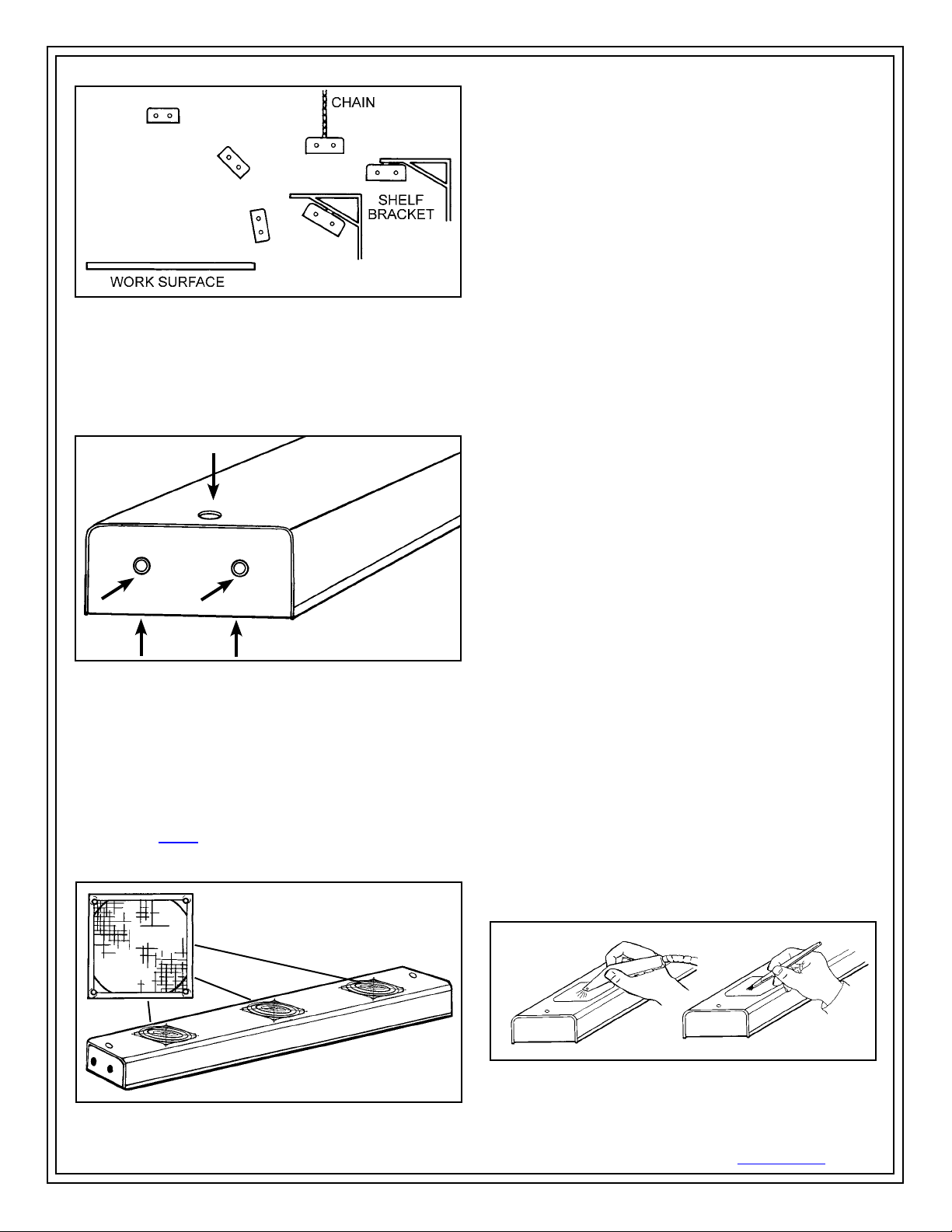
Figure 3. Mounting alternatives relative to the bench top
Mounting Suggestions
Mounting the ionizer is facilitated by five 1/4”-20 threaded
holes on each end and universal brackets supplied with
the unit. To avoid a potential shock hazard, be sure that
fasteners do not extend more than 1/2” into unit.
Figure 4. 1/4”-20 threaded mounting holes
Filter for Ionizer (Optional)
A filter is available for the High Output Overhead Ionizer.
Overhead ionizers operate more effectively when the air
is free of contaminants. The filter will allow the overhead
ionizer to operate longer between maintenance intervals.
Remove grills and install filters on the ionizer using screws
supplied (do not re-install grills over filters). Replacement
filters (item #94041) are available. For more information
on the filter, call our customer service department at
508-485-7390.
Air filter
Operation
After the ionizer has been securely mounted, connect
the power cord to the IEC connector on the back of the
unit and then to a convenient grounded receptacle. It is
recommended that the AC outlet be checked for proper
wiring and grounding, as the ionizer depends on a good
ground for balancing.
Set the front panel rocker fan switch to either “HIGH” or
“LOW” speed fan. Higher air flow will result in a faster
neutralization rate.
If the ionizer is used in a manner not specified by the
manufacturer, the protection provided by the ionizer
may be impaired.
Maintenance
“As with all ionizers, periodic maintenance will be needed to
provide optimum performance.” (Reference: IEC 61340-52:1paragraph 5.2.9).
The frequency of monitoring ionizers really depends on how
and where they are used. Since the majority of them use a
fan to transport the ions to the working area, the cleanliness
of the air directly affects their performance over time and
how often the emitters should be cleaned.
EIA-625 recommends checking ionizers every 6 months,
but this may not be suitable for many programs particularly
since an out-of-balance may exist for months before it
is checked again. ANSI/ESD S20.20 paragraph 6.1.3.1
Compliance Verification Plan Requirement states: “Test
equipment shall be selected to make measurements of
appropriate properties of the technical requirements that are
incorporated into the ESD program plan.” And paragraph
6.1.3.2. Compliance Verification Plan Guidance states: “In
addition to internal audits, external audits (Organization and
supplier of ESDS items) should be performed to ensure
compliance with planned requirements. Verifications should
include routine checks of the Technical Requirements in the
Plan. The frequency of verification checks should be based
on the control item usage, its durability and associated risk
of failure.”
Under normal conditions the ionizer will attract dirt and dust
(especially on the emitter and fan guards). To maintain
optimum performance, cleaning must be done on a regular
basis. The electrodes should be cleaned at least every 6
months. However, more frequent cleaning may be required
if used in environments with more contaminants.
Figure 5. Filter for ionizer
ESD Systems.com • 432 Northboro Road Central • Marlboro, MA 01752 • (508) 485-7390 • Fax (508) 480-0257 • Website: ESDSystems.com
TB-5522 Page 2 of 4
Figure 6. Cleaning the emitters and fan guards
© 2009 DESCO INDUSTRIES INC.
Employee Owned
Emitter needle cleaning is very simple and should be
done frequently. TURN THE IONIZER OFF. Blow off
contaminants on the emitter assemblies and fan guards with
clean dry air.
If the ionizer does not return to proper balance, then you
may need to clean each emitter point more thoroughly.
TURN THE UNIT OFF AND DISCONNECT THE POWER
CORD. With a non-linting swab or small brush dipped in
isopropyl alcohol wipe each emitter needle thoroughly.
Brush off emitters to assure that stray filaments of cleaning
material are completely removed. A soft cloth and alcohol
may be used to clean each fan guard.
Emitter Needle Replacement
The tri-metallic emitters should not require replacement
unless broken or damaged. Contact ESD Systems if
replacement is required.
Light Bulb Replacement
The High Output Overhead Ionizer features two fluorescent
light bulbs. They can be accessed and replaced by
removing the two covers located at the top of the ionizer.
The light bulbs should only be replaced by the same
compact fluorescent bulbs, 15 W max. NOTE: Never use
incandescent lamps in the High Output Overhead Ionizer.
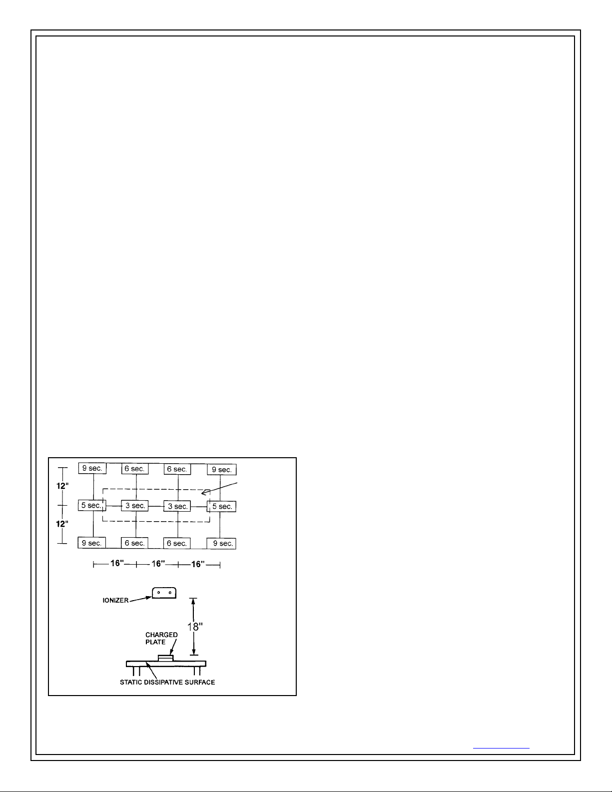
Neutralization Efficiency (Discharge Time)
The comparative efficiency of bench top ionizers is
determined by a standard test published by the ESD
Association Standard 3.1. The typical discharge rates
measured using this standard for the ionizer are shown in
the following diagram. The performance of the ionizer was
measured with the unit positioned at varying distances with
the fan speed on high and without a filter.
IONIZER
Theory of Operation
By definition, materials that are insulators cannot have
static charges removed via grounding as they do not
conduct electricity. Ionizer emitters flood an area with
millions of positive and negative charged electrons to
neutralize statically charged insulators.
SPI overhead ionizers employ a safe non-nuclear
Steady-State DC ionization source. Steady DC systems
consist of separate negative and positive ion emitters
connected by a pair of high-voltage cables to their
respective high-voltage power supplies. The ionizer’s
unique, closed loop monitoring circuitry monitors ion output
and automatically adjusts the unit to reach an equilibrium
at perfectly balanced ion flow. The ionizer is designed to
achieve balance under extreme conditions and is uniquely
able to maintain balance in almost any environment.
SPI ionizers meet the ANSI/ESD S20.20 minimum
recommended technical requirement range of less than ±50
volts voltage offset tested in accordance with ANSI ESD
S3.1. High Output Overhead Ionizers greatly exceed the
requirement providing ±5 volt auto balancing.
The unit’s circuitry also features a visual alarm, which alerts
the user to out of balance conditions caused by excessive
electrode contamination or the failure of either the positive
or negative power supply. When the Chargebuster is
ON and its output is balanced, the blue LED indicator on
the front of the unit will be steadily lit. If an out of balance
condition is detected the balance circuit will cause the
blue LED to flash until the problem is corrected. See the
maintenance section for recommended maintenance
procedures. This feature safeguards that the ionization is
balanced, protecting sensitive components and assemblies
from being exposed to harmful charging from an out of
balance ionizer.
The High Output Overhead Ionizer’s quiet and gentle fan
is designed so that it will not disturb personnel, paperwork,
or delicate parts. The LED indicator mounted on the face
of the unit allows the operator to easily verify whether it is
ON, OFF, or in need of maintenance. The ionizer’s emitter
electrode material will not require replacement during the
normal life of the product.
Figure 7. Discharge time in seconds from 1000 volts to 100
volts on a 6” x 6” charged plate per ANSI/ESD S3.1
ESD Systems.com • 432 Northboro Road Central • Marlboro, MA 01752 • (508) 485-7390 • Fax (508) 480-0257 • Website: ESDSystems.com
TB-5522 Page 3 of 4
The High Output Overhead Ionizer is engineered for
efficiency and durability. The unit’s automatic feedback
balancing circuitry eliminates the need for repeated
calibration, making this ionizer highly dependable and cost
effective.
© 2009 DESCO INDUSTRIES INC.
Employee Owned

Specifications
Input: 120 VAC - 50/60 Hz, 6A
Ozone: Less than 0.05 ppm
Airflow: 150-260CFM adjustable
Size: 40”L x 5-1/4”W x 2-3/4”H
Weight: 9.70 lbs
Cord: 7’6” cord set with IEC connector
Mounting: Five each 1/4”-20 threaded holes on
each end
Testing and Calibration
We recommend annual calibration of our ionizers. Ionizers
are tested and calibrated using a charged plate analyzer.
For proper testing we recommend a charged plate
analyzer and the procedure outlined in ESD Association
Standard 3.1. This standard may be obtained from the
ESD Association, 7902 Turin Road, Suite 4, Rome, NY
13440-2069, (315) 339-6937. ESD Systems will be happy
to send you information on SPI model 94052 Charged Plate
Analyzer. The High Output Overhead Ionizer is calibrated
to NIST traceable standards. Contact our Customer Service
Department for details.
Calibration Access Hole
(Make adjustments HERE)
Audio On/Off
Alarm Adjustment
Balance Adjustment
Health
There are no known health risks associated with our
devices. The emitters work at about 4-6 kV and can create
ozone, but there have been no significant measurement
of ozone from our emitter sets, as all our existing units
test well below the OSHA limit of 0.05 ppm ozone. For
additional safety information, see “Dispelling an Old Myth”
written by William Metz of Hewlett-Packard published in
Evaluation Engineering magazine, September 2001.
Limited Warranty
ESD Systems.com expressly warrants that for a period of one (1) year
from the date of purchase, our High Output Overhead Ionizers will be
free of defects in material. Within the warranty period, the material will
be tested and replaced at our option, free of charge. Call Customer
Service at 508-485-7390 for a Return Material Authorization (RMA)
and proper shipping instructions and address. You should include a
copy of your original packing slip, invoice, or other proof of purchase
date. Any material under warranty should be shipped prepaid to the
ESD Systems.com factory. Warranty repairs will take approximately
one week.
Warranty Exclusions
THE FOREGOING EXPRESS WARRANTY IS MADE IN LIEU
OF ALL OTHER PRODUCT WARRANTIES, EXPRESSED AND
IMPLIED, INCLUDING MERCHANTABILITY AND FITNESS
FOR A PARTICULAR PURPOSE WHICH ARE SPECIFICALLY
DISCLAIMED. The express warranty will not apply to defects or
damage due to accidents, neglect, misuse, alterations, operator error,
or failure to properly maintain, clean or repair products.
Limit of Liability
Electronic ionizers use high voltage corona discharge and should
not be used in or near flammable or explosive environments. In no
event will ESD Systems.com or any seller be responsible or liable for
any injury, loss or damage, direct or consequential, arising out of the
use of or the inability to use the product. Before using, users shall
determine the suitability of the product for their intended use, and
users assume all risk and liability whatsoever in connection therewith.
Figure 8. Calibration and position of the Charged Plate
Analyzer
Adjustments
For Audio On/Off and Alarm and Balance Adjustment see
Figure 8.
ESD Systems.com • 432 Northboro Road Central • Marlboro, MA 01752 • (508) 485-7390 • Fax (508) 480-0257 • Website: ESDSystems.com
TB-5522 Page 4 of 4
© 2009 DESCO INDUSTRIES INC.
Employee Owned
 Loading...