

TECHNICAL BULLETIN TB-3031
Chargebuster® Overhead Ionizer
Operation, Installation, and Maintenance
distance of 30 cm (12 inches); or B) Use ionization or other
charge mitigating techniques to neutralize the charge.”
(ANSI/ESD S20.20-2007 section 8.3)
“The primary method of static charge control is direct
connection to ground for conductors, static dissipative
materials, and personnel. A complete static control
program must also deal with isolated conductors that cannot
be grounded, insulating materials (e.g., most common
plastics), and moving personnel who cannot use wrist or
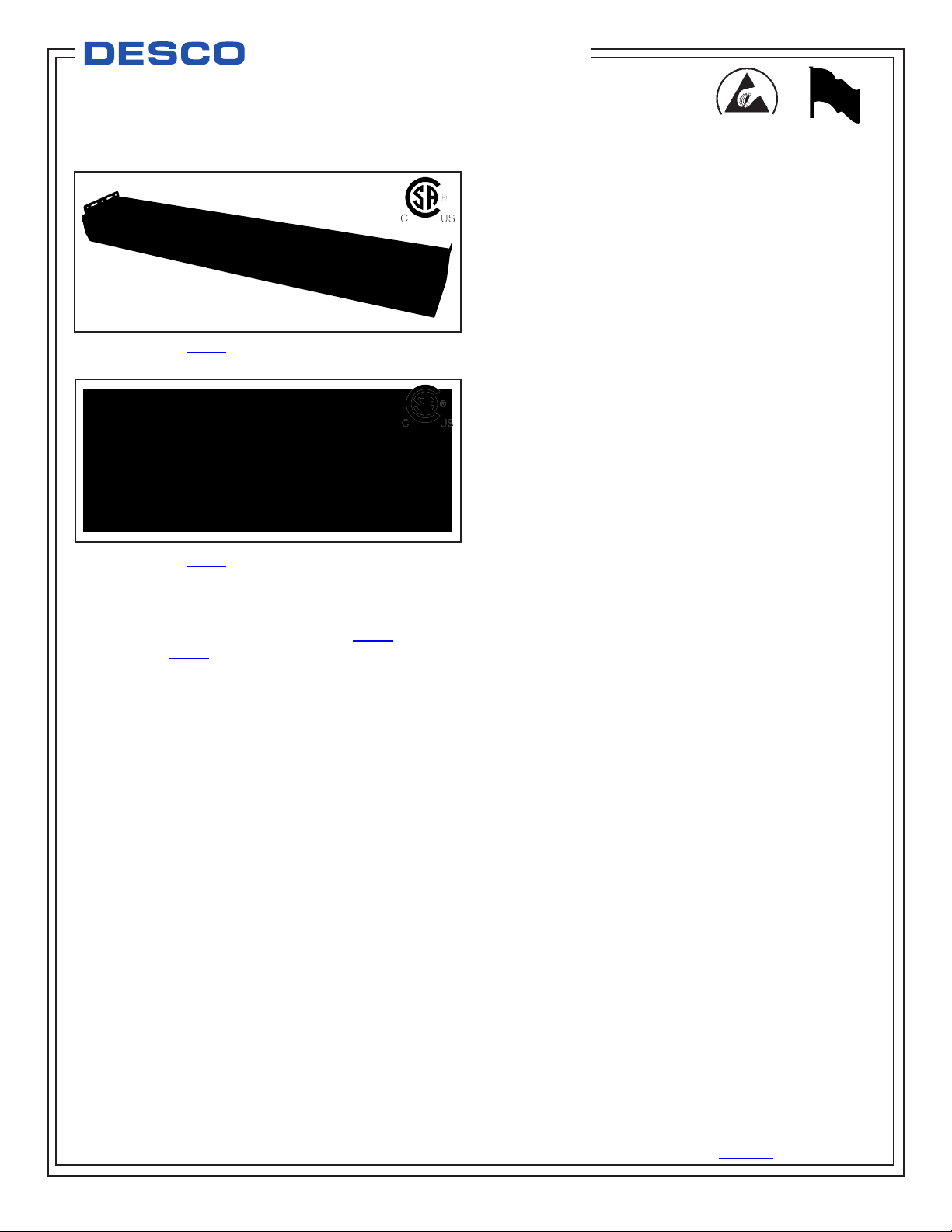
Figure 1. Desco 60473 Chargebuster Overhead Ionizer
Figure 2. Desco 60640 Chargebuster Overhead Ionizer
Description
The Chargebuster® overhead ionizers are steady state DC
ionizers designed to cover 2 foot by 5 foot (60473) or 2
foot by 4 foot (60640) for use in ESD sensitive work areas:
calibration, test, final assembly, or repair procedures. The
specially designed 3-speed fan modules create better
coverage, consistent offset voltage (±10 Volts), and superior
discharge times(<3 seconds) tested per ANSI/ESD STM
3.1. The Chargebuster® overhead ionizers are equipped
with a Auto-Feedback system, that continually optimizes the
performance and will automatically shut down the and alarm
if/when supply voltage drops to the ionizer. The ionizers
can be used with 110V or 220V power sources.
“Necessary non-conductors in the environment cannot
lose their electrostatic charge by attachment to ground.
Ionization systems provide neutralization of charges on
these necessary non-conductive items (circuit board
materials and some device packages are examples of
necessary non-conductors). Assessment of the ESD
hazard created by electrostatic charges on the necessary
nonconductors in the work place is required to ensure
that appropriate actions are implemented, commensurate
with risk to ESDS [ESD sensitive] items”. (ANSI/ESD
S20.20-2007 Foreword)
“In order to mitigate field-induced CDM [Charged Device
Model] damage, the ESD program shall include a plan for
the handling of process-required insulators. If the field
exceeds 2,000 volts/inch, steps shall be taken to either: A)
Separate the insulator from the ESD-sensitive device by a
heel straps or ESD control flooring and footwear.
Air ionization is not a replacement for grounding methods.
It is one component of a complete static control program.
Ionizers are used when it is not possible to properly
ground everything and as backup to other static control
methods. In clean rooms, air ionization may be one of the
few methods of static control available.” (ESD Handbook
ESD TR20.20 Ionization, section 5.3.6.1)
“All ionization devices will require periodic maintenance for
proper operation. Maintenance intervals for ionizers vary
widely depending on the type of ionization equipment and
use environment. Critical clean room uses will generally
require more frequent attention. It is important to set-up
a routine schedule for ionizer service. Routine service is
typically required to meet quality audit requirements.” (ESD
Handbook ESD TR20.20 section 5.3.6.7 Maintenance /
Cleaning)
Packaging
1 Chargebuster Overhead Ionizer
1 Hanging Kit
1 Power Cord
3 Emitter Point Cleaners
1 Certificate of Calibration
Installation
Input voltage is selected with the two internal jumpers on
JH1. For 110 volt jumper setting, a jumper must be in place
shorting pin 1 to 2 and another shorting pin 3 to 4 (see
Figure 3). For 220 volt jumper setting, a single jumper must
be in place shorting pin 2 to 3 only (see figure 4). Make
sure setting is correct before applying power.
Note: Unit shipped set at 110V
Before installing the unit, verify that the AC outlet is properly
connected to ground. The unit must have a good ground
to maintain proper offset voltage balance. Install the unit in
the desired location, making sure that the airflow will not be
restricted. Be sure the “OFF / ON” switch located on the
rear of the unit is in the OFF position. Plug the power cord
into the unit and then into the appropriate AC power source.
Made in America
DESCO EAST - One Colgate Way, Canton, MA 02021-1407 • (781) 821-8370 • Fax (781) 575-0172 • Web Site: Desco.com
TB-3031 May 2010 Page 1 of 4
DESCO WEST - 3651 Walnut Avenue, Chino, CA 91710 • (909) 627-8178 • Fax (909) 627-7449
© 2010 DESCO INDUSTRIES INC.
Employee Owned
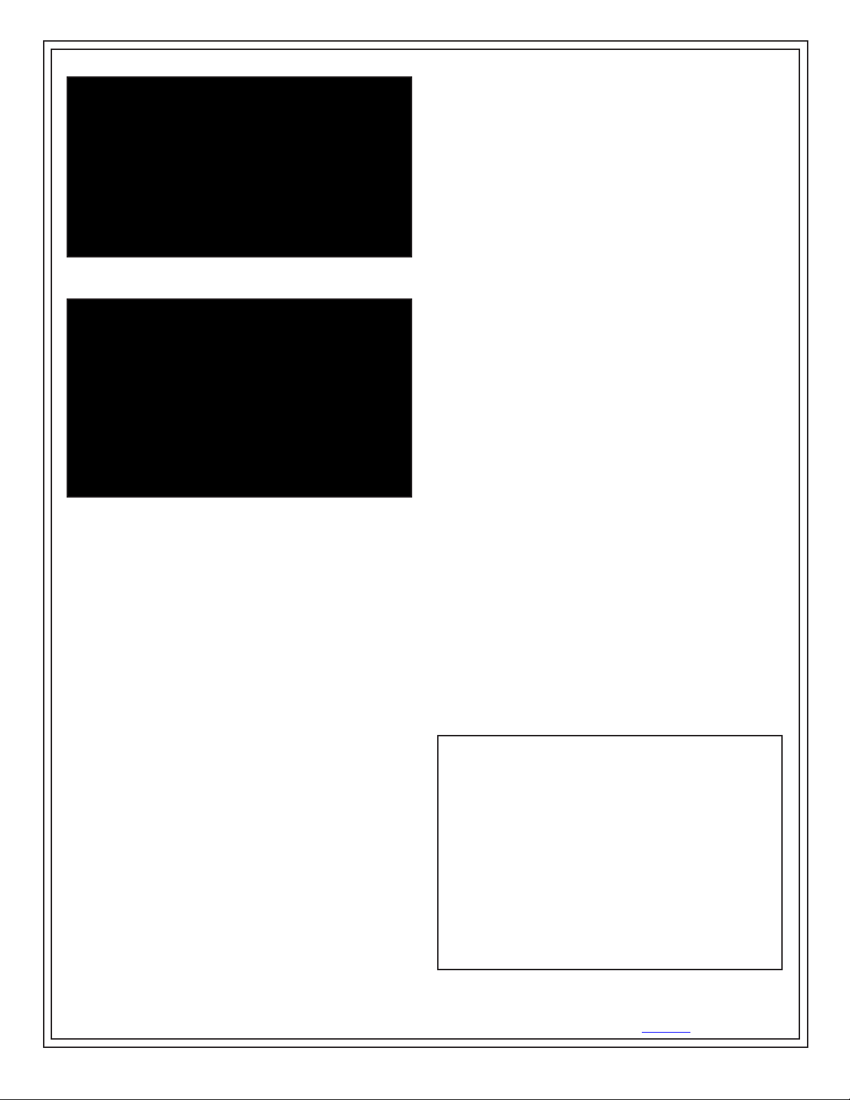
Figure 3. 110 volt jumper setting
Figure 4. 220 volt jumper setting
Under normal conditions the ionizer will attract dirt and dust
(especially on the emitter electrodes). To maintain optimum
neutralization efficiency and operation, cleaning should be
performed on a regular basis.
When the unit enters shutdown mode, ionization will be
stopped, the LED on the front of the unit will change to a
steady RED, and the audible alarm will sound continuously.
If the ionizer enters shutdown mode, it must be turned OFF
and then back ON to reset the unit.
NOTE: The AC power cord MUST be disconnected
before the unit is disassembled for maintenance. The
emitter electrodes should be cleaned using the included
cleaners or a swab damp with isopropyl alcohol. First,
turn the unit OFF and unplug the power cord. Then
remove each fan grill located on the top-side of the ionizer
by disengaging all 4 screws per grill. Clean all emitter
electrodes. After cleaning the emitter electrodes, re-attach
all the removed grills. Plug in the power cord and turn the
unit back ON.
The emitter electrodes should not require replacement
during the life of the unit with normal handling.
Replacement emitter electrodes can be ordered if
necessary.
The best practice would be to verify the balance (offset
voltage) of the unit with a charged plate monitor after
cleaning.
Operation
Set the fan speed switch on the rear of the unit to the LOW,
MED, or HIGH position. Higher airflow will result in faster
discharge times. Position the unit so that the maximum
airflow is directed at the items or area to be neutralized.
Turn the unit ON.
When the unit is first turned on, it will conduct a self-test.
The audible alarm will sound and then the LED will cycle
through RED, YELLOW, and GREEN. The LED will remain
GREEN during normal operation.
BALANCE (OFFSET VOLTAGE) ADJUSTMENT
The Chargebuster Overhead Ionizer is an auto-balancing
unit. However, tuning or manual adjustment can be
accomplished by inserting a small screwdriver or trimmer
adjustment tool into the balance (offset voltage) adjustment
hole located on the front of the unit. To increase the output
in a positive direction, turn the potentiometer in a clockwise
direction. Conversely, to increase the output in a negative
direction, turn the potentiometer in a counter-clockwise
direction. Once the desired balance point has been
achieved, the alarm reset button must be pressed to set the
balance point.
MAINTENANCE / ALARMS
If the supply voltage drops from 120 Volts to below 85 Volts,
the unit will shut down, the audible alarm will beep, and the
LED will blink RED. The unit will automatically reset when
the minimum voltage is restored.
NEUTRALIZATION (DISCHARGE) TIMES
The comparative efficiency of overhead ionizers is
determined by a standard test published by ANSI/ESD
S3.1. Typical positive and negative discharge times (in
seconds from 1000 volts to 100 volts and from -1000 volts
to -100 volts) measured using this standard are shown
below. The performance of the ionizer was measured with
the unit positioned as shown, with the fan speed on high,
and without a filter.
The typical discharge times measured using this standard
for the ionizer are shown in the following diagram. They are
not guaranteed maximum discharge times.
Figure 5. Neutralization (discharge) times - 2 fan ionizer
TB-3031 Page 2 of 4
DESCO EAST - One Colgate Way, Canton, MA 02021-1407 • (781) 821-8370 • Fax (781) 575-0172 • Web Site: Desco.com
DESCO WEST - 3651 Walnut Avenue, Chino, CA 91710 • (909) 627-8178 • Fax (909) 627-7449
© 2010 DESCO INDUSTRIES INC.
Employee Owned

Figure 6. Neutralization (discharge) times - 3 fan ionizer
Note: Reference ANSI/ESD STM 3.1. The distance from
the ionizer to the charged plate is 18”.
Specifications:
AIR VOLUME - 60473
150-300cfm
AIR VOLUME - 60640
100-200cfm
MOUNTING
May be rigid-mounted or suspended from ceiling
OZONE
Less than 0.05ppm
WEIGHT - 60473
10 lbs. (4.54 kg)
WEIGHT - 60640
7 lbs. (3.18 kg)
Compliance Verification
ANSI/ESD S20.20-2007 added Compliance Verification
columns to the Tables. The test method for Compliance
Verification is ESD TR53. Ionizers should be tested
periodically for both polarity’s discharge times, and for offset
voltage balance per ESD Association Technical Report ESD
TR53 Compliance Verification of ESD Protective Equipment
and Materials. The most accurate tool to use for this is a
Charged Plate Monitor. Alternatively, a portable battery
operated Ionization Test Kit can be used.
Per ESD TR 53 ANNEX A “Test Frequency, The objective
of the periodic test procedures listed in this document is
to identify if significant changes in ESD equipment and
materials performance have occurred over time.
BALANCE (OFFSET VOLTAGE)
±10 volt, typical; ±20 volts maximum at 65°F to 80°F, R.H.:
15% to 65%
CHASSIS
White powder coated steel housing
DIMENSIONS - 60473
3.5" H x 6.5" W x 37" L
(8.9cm H x 16.5cm W x 94.0 cm L)
DIMENSIONS - 60640
3.5" H x 6.5" W x 24" L
(8.9cm H x 16.5cm W x 61.0cm L)
EMITTER POINTS
.050" diameter pure tungsten for improved mechanical
strength and ionization stability
FUSE
400mA slow blow
HIGH VOLTAGE POWER SUPPLY
5.5 kV DC nominal
INPUT POWER
AC line power, 120 VAC, 50/60Hz
(can be changed internally to 220V)
Test frequency limits are not listed in this document,
as each user will need to develop their own set of test
frequencies based on the critical nature of those ESD
sensitive items handled and the risk of failure for the ESD
protective equipment and materials.
Per ESD TR53, all the test locations of @3.1 are not
required; rather “Measurements should be made at the
location where ESD sensitive items are to be ionized. For
many EPA ESD Control items sampling is appropriate for
Compliance Verification, however, best practice is to test
each ionizer.
Calibration
When an alarm sounds, most users will clean emitter
pins (see Maintenance / Alarms section) and calibrate the
ionizer. Per ESD TR 53 section 5.3.6.7.1 “The best practice
is to measure the offset voltage and discharge times, clean
the unit, including emitter points and air filters if present,
offset voltage to zero (if adjustable), and then repeat offset
voltage and discharge time testing. If the unit does not
meet offset voltage specifications or minimum established
discharge time limits, further service is indicated.
Manufacturers should provide details on service procedures
and typical service intervals.”
ION EMISSION
Steady state DC with sense feedback
DESCO WEST - 3651 Walnut Avenue, Chino, CA 91710 • (909) 627-8178 • Fax (909) 627-7449
DESCO EAST - One Colgate Way, Canton, MA 02021-1407 • (781) 821-8370 • Fax (781) 575-0172 • Web Site: Desco.com
TB-3031 Page 3 of 4
© 2010 DESCO INDUSTRIES INC.
Employee Owned

Most companies will assign a number or otherwise
identify each ionizer and setup a compliance Verification /
Maintenance / Calibration schedule. If the ionizers all test
good, the data can justify lengthening the calibration period.
If ionizers require adjustment the calibration period should
be shortened. Although ESD TR53 does not advise a test
frequency, JESDD625-A (Revision of EIA-625) recommends
ionizers be tested semiannually, noting to use “S3.1 except
the number of measurement points and locations may be
selected based on the application.”
NOTE: A charged plate analyzer or monitor should be used
in order to properly calibrate the Chargebuster Overhead
Ionizer. Desco EMIT offers the 50555 Charged Plate
Analyzer.
I. Properly setup the ionizer as described in the
Installation procedure on page 1.
II. Turn the unit ON and set the FAN SPEED to HIGH.
III. Position the charged plate analyzer 18 inches
underneath one of the fans of the Chargebuster
Overhead Ionizer.
IV. Push and hold the ALARM RESET button on the
ionizer until the STATUS LED turns red (see Figure 7).
Release the button and the LED should switch back to
green. This allows the user to calibrate the balance
(offset voltage) of the ionizer without setting off the
alarm.
Figure 7. Calibration controls
V. The balance (offset voltage) of each fan should be
within 0 and ±15 volts. The required limit per
ANSI/ESD S20.20 is less than ± 50 volts. To increase
the output in a positive direction, turn the BALANCE
ADJUST potentiometer in a clockwise direction. To
increase the output in a negative direction, turn the
BALANCE ADJUST potentiometer in a counter clockwise direction.
VI. Test the neutralization (discharge) time by applying a
±1,000 volt on the charged plate. The neutralization
(discharge) time should be less than 3 seconds when
charged plate analyzer is directly under a fan. See
figures 5 and 6 for typical discharge times. The
required limit per ANSI/ESD S20.20 is “user defined”.
VII. Submit the balance (offset voltage) to the ionizer’s
control circuit by quickly pressing the ALARM RESET
button. The STATUS LED should turn off and then
illuminate green to verify that the control circuit was
successfully programmed.
VIII. Test each fan’s alarm by shorting its two grills located
on the bottom side of the ionizer (see Figure 8). The
alarm should sound and the STATUS LED should
illuminate red.
Figure 8. Shorting the ionizer’s two fan grills
Limited Warranty
Desco expressly warrants that for a period of one (1) year from
the date of purchase Desco Chargebuster Overhead Ionizers will
be free of defects in material (parts) and workmanship (labor).
Within the warranty period, a credit for purchase of replacement
Desco Chargebuster Overhead Ionizers, or, at Desco’s option,
the Chargebuster Overhead Ionizer will be repaired or replaced
free of charge. Call our Customer Service Department at
909-627-8178 (Chino, CA) or 781-821-8370 (Canton, MA) for
a Return Material Authorization (RMA) and proper shipping
instructions and address. Please include a copy of your original
packing slip, invoice, or other proof of date of purchase. Any unit
under warranty should be shipped prepaid to the Desco factory.
Warranty replacements will take approximately two weeks.
If your unit is out of warranty, call our Customer Service
Department at 909-627-8178 (Chino, CA) or 781-821-8370
(Canton, MA) for a Return Material Authorization (RMA) and
proper shipping instructions and address. Desco will quote repair
charges necessary to bring your unit up to factory standards.
Warranty Exclusions
THE FOREGOING EXPRESS WARRANTY IS MADE IN LIEU
OF ALL OTHER PRODUCT WARRANTIES, EXPRESSED AND
IMPLIED, INCLUDING MERCHANTABILITY AND FITNESS
FOR A PARTICULAR PURPOSE WHICH ARE SPECIFICALLY
DISCLAIMED. The express warranty will not apply to defects or
damage due to accidents, neglect, misuse, alterations, operator
error, or failure to properly maintain, clean or repair products.
Limit of Liability
In no event will Desco or any seller be responsible or liable for
any injury, loss or damage, direct or consequential, arising out of
the use of or the inability to use the product. Before using, users
shall determine the suitability of the product for their intended use,
and users assume all risk and liability whatsoever in connection
therewith.
TB-3031 Page 4 of 4
DESCO EAST - One Colgate Way, Canton, MA 02021-1407 • (781) 821-8370 • Fax (781) 575-0172 • Web Site: Desco.com
DESCO WEST - 3651 Walnut Avenue, Chino, CA 91710 • (909) 627-8178 • Fax (909) 627-7449
© 2010 DESCO INDUSTRIES INC.
Employee Owned
 Loading...