

Desco 41290 Installation Manual
TECHNICAL BULLETIN TB-5514
Mini Meg™ Pocket Megohmmeter
Operation and Maintenance
Installation
Remove the meter from the carton and inspect for
damage. Each unit should be fully charged and
includes:
1 Mini Meg Pocket Megohmmeter
1 Surface-to-Ground, cord assembly
1 Installed 9V battery
Properly store the megohmmeter and its component
assemblies when not in use.
Operation
The Micro Meg will perform Surface Resistivity
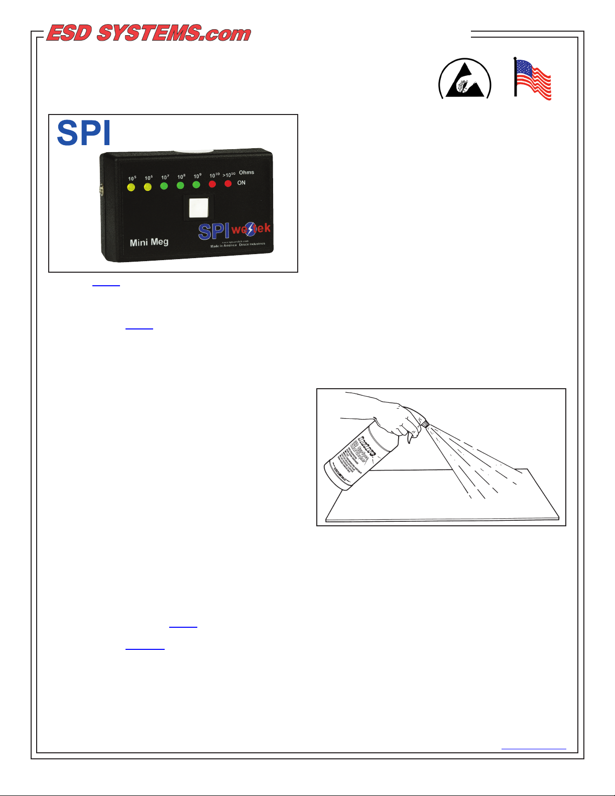
Figure 1. 94055 Mini Meg Pocket Megohmmeter
Description
The SPI Westek 94055 Mini Meg Pocket
Megohmmeter is a portable test instrument designed
for measuring both surface and surface-to-ground
resistance of static dissipative and conductive
materials. Seven color-coded LEDs, read from
right to left, easily identify static dissipative and
conductive ranges. The Mini Meg will test materials
with surface resistivity of 1 x 10E5 to 1 x 10E10 . This
test instrument is ideally suited for Quality Control
and Field Service personnel as well as for use in
routine auditing of your ESD protective materials. The
Mini Meg features simple one-button operation and a
9V battery for ease of use and maximum portability.
This auto-ranging instrument weighs only six ounces.
The high-impact plastic case ensures durability despite
the meter’s light weight.
and Surface-to-Ground resistance measurements.
Work surfaces and materials to be tested should be
cleaned prior to testing to ensure that surface dirt and
contamination do not affect results. It is recommended
that non-silicone and non-alcohol based cleaners such
as ESDSystems.com’s Reztore™ Surface and Mat
Cleaner be used for regular cleaning of ESD protective
work surfaces. When non-ESD surfaces are being
used, Reztore™ Topical Antistat is recommended for
eliminating static charge generation.
Made in America
The Mini Meg has not been designed to meet ESD
S4.1 test equipment requirements and therefore
measurements obtained with this device may not
agree with measurements taken according to the ESD
S4.1 test procedure. This test instrument is intended
for use only as an auxiliary tool for monitoring surface
resistance performance.
If you are interested in obtaining a meter which does
meet all the test equipment requirements of ESD S4.1,
we recommend our model 41290 Surface Resistance
Test Kit. For more information on this product ask for
Techical Bulletin PS-2111.
ESD Systems.com • 432 Northboro Road Central • Marlboro, MA 01752 • (508) 485-7390 • Fax (508) 480-0257 • Website: ESDSystems.com
TB-5514 October 2010 Page 1 of 4
Figure 2. Cleaning the work surface before testing.
Surface and Surface-to-Ground resistance readings
are indicated by the series of LEDs on the face of the
meter. The LEDs are read from right to left as follows:
1. RED – Meter is on and battery is functioning
2. GREEN – 5 x 10E10
3. GREEN – 1 x 10E9
4. GREEN – 1 x 10E8
5. GREEN – 1 x 10E7
6. YELLOW – 1 x 10E6
7. YELLOW – 1 x 10E5
© 2010 DESCO INDUSTRIES INC.
Employee Owned
Each LED indicates one order of magnitude of
resistance. If the test surface is conductive to less than
10E5, all the LEDs will be lit. If it is neither conductive
nor static dissipative, only the red “On” LED will be lit.
Surface Resistivity Measurements
Surface resistivity measurements are made using only
the meter without the cord assembly. When the white
button is depressed a test voltage of 9 VDC is applied
to the meter’s center electrode. The second resistivity
electrode will supply the resistance bridge and provide
the measurement. To perform surface resistivity tests,
follow these simple instructions:
A. Check battery operation by depressing the white
button on the center of the megohmmeter. The red
“On” lamp at the far right should light to indicate that
the unit is functioning properly.
B. Place the meter on the surface being tested. All
three electrodes should make contact with the surface.
C. Press the white button. The surface resistance will
be indicated by the number of LEDs which light up.
The more lights illuminated, the greater the conductivity
of the surface. The measurement is in ohms/square
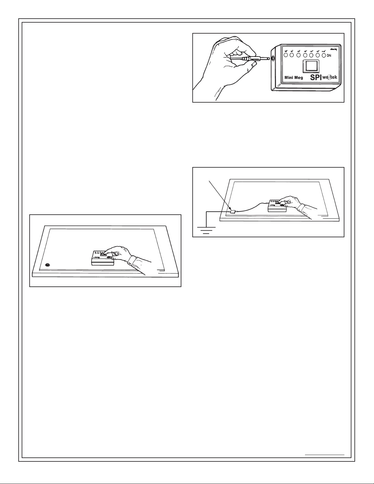
Figure 4. Installing Surface-to-Ground cord assembly.
C. Place the Mini Meg on the test surface.
D. Connect the test cord to the ground-point for the
surface.
E. Press the white button. The LEDs will indicate the
test results. The measurement is in ohms.
GROUND
POINT
WORK SURFACE
Figure 3. Measuring surface resistivity.
Surface-to-Ground Measurements (RTG)
The Surface-to-Ground feature is best used when
expected results are less than 10E6 ohms, and
when residual voltages can be removed from the test
surface. Residual voltages may cause the two upper
range LEDs to light, resulting in a false reading.
When the Surface-to-Ground cord is plugged in,
voltage is diverted from the center electrode to the
cord in order to measure resistance. When making
Surface-to-Ground tests, follow these procedures:
A. Check battery operation by depressing the white
button. The red “On” lamp will indicate that the unit is
functioning properly.
B. Plug the Surface-to-Ground cord into the left side of
the megohmmeter.
Figure 5. Measuring Surface-to-Ground resistance.
F. Unplug the cord when testing is finished.
Battery Operation
Battery function is automatically checked by the unit
when the meter is turned on. If the battery voltage
drops below 8 VDC, the red LED on the far right of the
meter will not light, indicating a “low battery” condition.
Replace battery with a new 9V alkaline battery.
Maintenance
Your Mini Meg will require very little maintenance,
and there are few user-serviceable parts. If your
meter requires service beyond the simple procedures
described below please contact the factory.
Electrode Cleaning
To assure accurate measurements the electrodes
should be kept as clean as possible. A thorough
cleaning at least every 3 months is recommended. The
following is the recommended cleaning procedure:
1. Carefully remove the electrodes from their
snap-jacks using a screw driver or other blunt flat
bladed object. Avoid scratching or bending electrodes.
ESD Systems.com • 432 Northboro Road Central • Marlboro, MA 01752 • (508) 485-7390 • Fax (508) 480-0257 • Website: ESDSystems.com
TB-5514 Page 2 of 4
© 2010 DESCO INDUSTRIES INC.
Employee Owned
 Loading...