

Page 1
TECHNICAL BULLETIN TB-3078
Zero Volt Monitor
Installation, Operation and Maintenance
ANSI/ESD S20.20 section 7.3 states “Compliance
verification records shall be established and maintained
to provide evidence of conformity to the technical
requirements.” Per ANSI/ESD S1.1 Annex A.3 Daily
(wrist strap system) testing may be omitted if constant
monitoring used.” Per ESD Handbook ESD TR 20.20
section 5.3.2.4.4 “Typical Test programs recommend
that wrist straps that are used daily should be tested
daily. However, if the products that are being produced
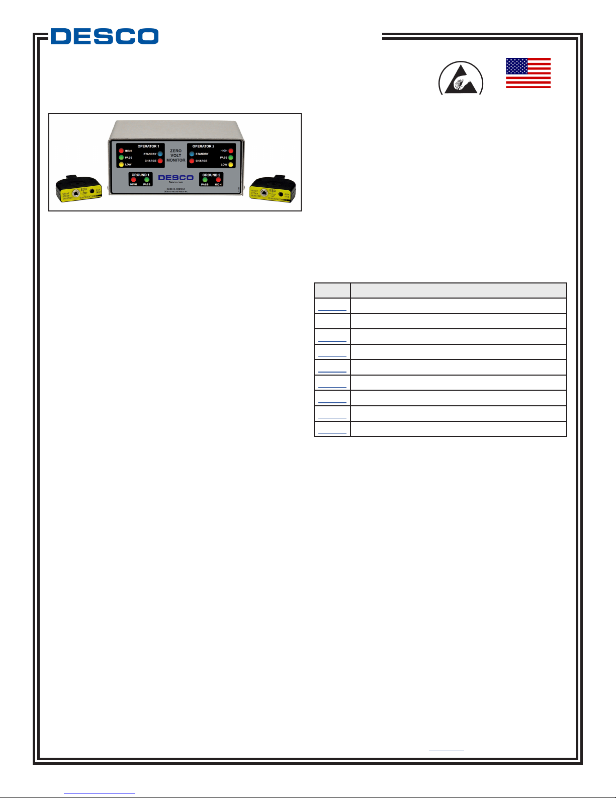
Figure 1. Desco 19668 Zero Volt Monitor
Description
The Desco 19668 Zero Volt Monitor is a dual
workstation continuous monitor. It continuously monitors
the path-to-ground integrity of two operators and two
ESD worksurfaces. It also will indicate if voltage greater
than ±1.25 V is induced onto the operator. Audio
and visual alarms activate in failure situations. The
Desco Zero Volt Monitor provides stable continuous
monitoring of the path-to-ground and presence of two
1 megohm resistors of an operator’s dual-wire wrist
strap. Audio and visual alarms activate (in less than 500
milliseconds) when the wrist strap connection points
are intermittent. The Desco Zero Volt Monitor also
monitors for a worksurface path-to-ground less than 3.5
megohms. All Desco Zero Volt Monitors are calibrated
to NIST standards and include a certificate. A calibration
unit is available to preform compliance verification at the
workbench without taking the monitor out of service.
are of such value that knowledge of a continuous,
reliable ground is needed, and then continuous
monitoring should be considered or even required.”
The Zero Volt Monitor and its accessories are available
in the following item numbers:
Item Description
19668 Zero Volt Monitor
50524 Limit Comparator
50529 Replacement Operator Remote Kit, Black
50530 Replacement Operator Remote Cable, Black
50531 Replacement Operator Remote Kit, White
50532 Replacement Operator Remote Cable, White
50533 Replacement Operator Remote
50534 Replacement Hardware Kit
19262 Replacement Power Adapter, 12 VDC
Made in the
United States of America
Desco Zero Volt Monitor Technology
The Desco Zero Volt Monitor uses electrical loop
resistance technology. Dual test signals are placed
onto each of the dual-wire wrist strap's conductors
to negate finger-tip voltage. Resistance is monitored
with a continuous split test signal sent through both
conductors, across the skin of the operator, and
returning to the monitor through the opposite conductor.
Desco Zero Volt Monitors determine that the operator’s
path-to-ground is between the 2 megohms lower limit
and 10 megohms upper limit. Additionally, the Desco
Zero Volt Monitor determines if voltage greater than
±1.25 V has accumulated on the operator.
DESCO WEST - 3651 Walnut Avenue, Chino, CA 91710 • (909) 627-8178
DESCO EAST - One Colgate Way, Canton, MA 02021-1407 • (781) 821-8370 • Website: Desco.com
Packaging
1 Zero Volt Monitor
1 Power Adapter, 12 VDC, with interchangeable plugs
(North America, UK/Asia, Europe)
2 Operator Remotes
1 Operator Remote Cable, Black
1 Operator Remote Cable, White
1 Monitor Ground Cord, Green
1 Mat Monitor Cord, Black
1 Mat Monitor Cord, White
2 Mat Ground Cords, Green
1 Hardware Kit
1 Certificate of Calibration
TB-3078 Page 1 of 6
March 2019
© 2019 DESCO INDUSTRIES INC
Employee Owned
Page 2
Features and Components
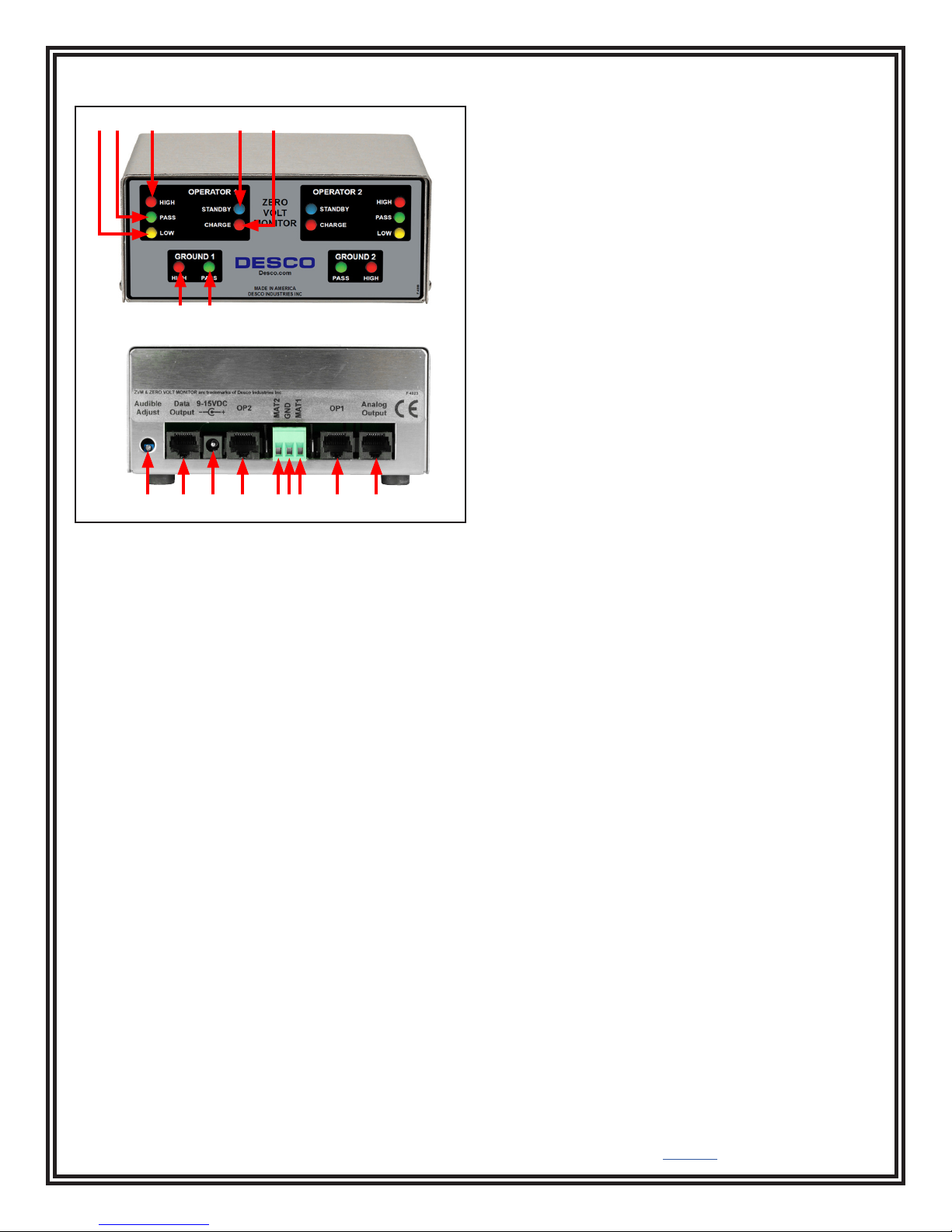
A B C D E
L. Mat 2 Terminal: Monitors worksurface mat 2.
Connect the black mat monitor cord here.
M. Monitor Ground Terminal: Common ground point
for the monitor. Connect the green monitor ground cord
here.
N. Mat 1 Terminal: Monitors worksurface mat 1.
Connect the white mat monitor cord here.
O. Operator 1 Remote Jack: Connect the white
operator remote cable here.
P. Analog Output: For manufacturer use only.
F G
H I J K LMN O P
Figure 2. Zero Volt Monitor features and components
A. Operator Fail Low LED: Illuminates and audible
alarm sounds when the operator’s resistance is below
the test limit.
B. Operator Pass LED: Illuminates when the operator
is properly grounded.
C. Operator Fail High LED: Illuminates and audible
alarm sounds when the operator’s resistance is above
the test limit.
D. Operator Standby LED: Illuminates when the
operator is not connected to the operator remote.
E. Operator Charge LED: Illuminates and audible alarm
sounds when the operator's body voltage is greater than
±1.25 VDC.
F. Mat Fail LED: Illuminates and audible alarm sounds
when the worksurface mat is not properly grounded.
G. Mat Pass LED: Illuminates when the worksurface
mat is properly grounded.
H. Alarm Audible Adjustment: Turn the trimpot
clockwise to increase the audible alarm volume. Turn
the trimpot counter-clockwise to decrease the audible
alarm volume.
Installation
1. Determine the mounting location of the Zero Volt
Monitor. The front panel should be visible to both
operators.
2. Determine the mounting locations of the operator
remotes. Be sure to install the remotes at a distance
that enables its leads to reach the back of the
monitor.
3. Install tinned wire ends of the mat cords to their
appropriate screw terminal block located at the back
of the monitor.
4. Attach the worksurface mats to ground using the
green mat ground cords. Install the ring terminal end
of the cord to an appropriate ground point. Attach
the snap terminals to the snaps on the worksurface
mats.
5. Install the tinned wire end of the green monitor
ground cord to the ground terminal located at the
back of the monitor. Install its ring terminal to an
appropriate ground point. Be sure to use a different
ground point than the one used for the mats. The
face plate screw of a grounded AC wall outlet may
provide a convenient connection point.
6. Route the mat cords from the back of the monitor
to the snaps on worksurface mats. The white cord
is for worksurface mat #1. The black cord is for
worksurface mat #2.
7. Insert the operator remote cables into their
appropriate jacks located at the back of the monitor.
The white cable is for operator #1. The black cable
is for operator #2.
8. Connect the power adapter to the power jack
located at the back of the monitor. Plug the power
adapter into a proper AC power outlet. The monitor
is now powered.
I. Data Output: For manufacturer use only.
J. Power Jack: Connect the included 12 VDC power
adapter here.
K. Operator 2 Remote Jack: Connect the black
operator remote cable here.
DESCO WEST - 3651 Walnut Avenue, Chino, CA 91710 • (909) 627-8178
DESCO EAST - One Colgate Way, Canton, MA 02021-1407 • (781) 821-8370 • Website: Desco.com
TB-3078 Page 2 of 6
© 2019 DESCO INDUSTRIES INC
Employee Owned
Page 3
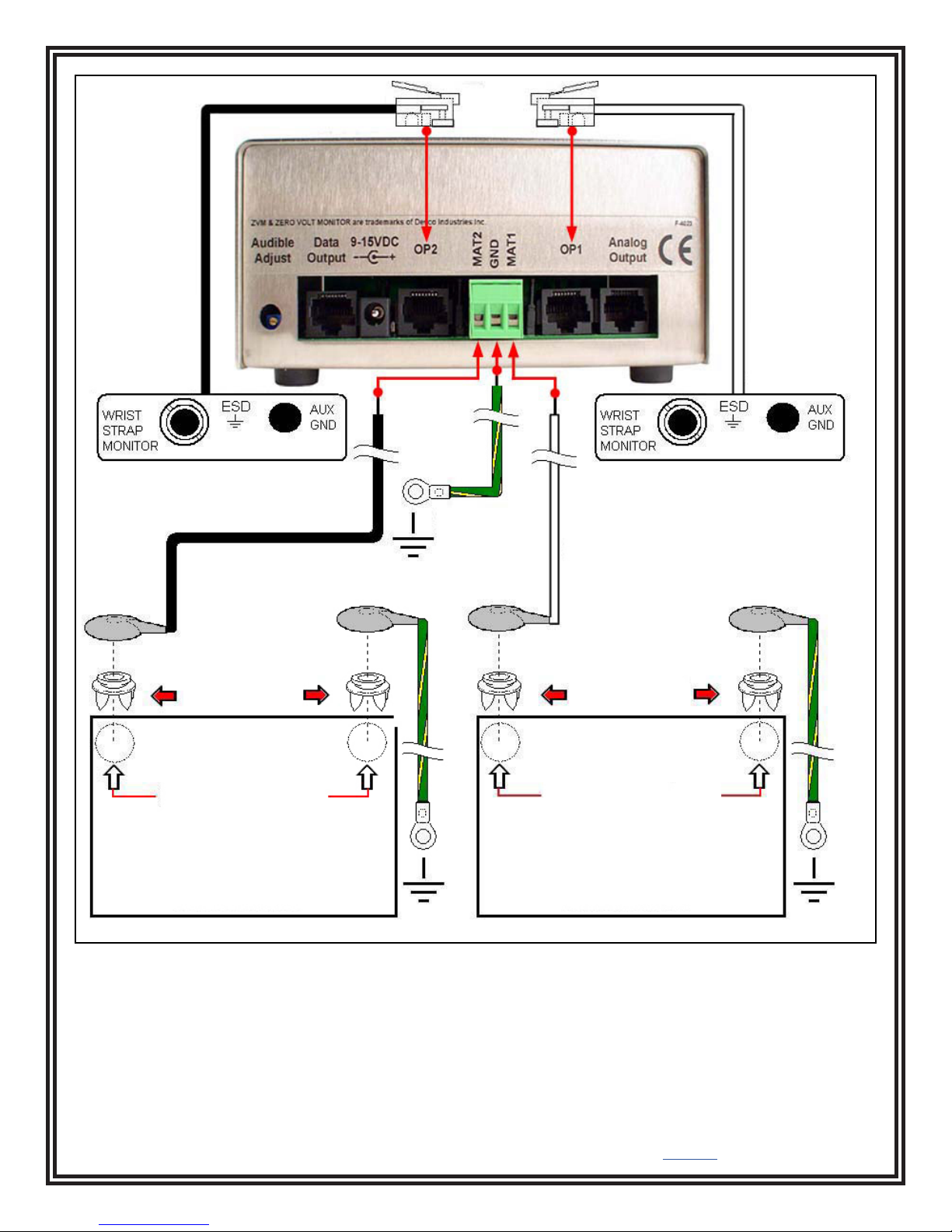
OPERATOR 2
REMOTE JACK
OPERATOR 1
REMOTE JACK
MAT 2 CORD
10mm PUSH &
CLINCH SNAPS
10mm snaps need to pierce
and clinch bottom side of mat
and be 12" - 72" apart.
WORKSURFACE 2
Figure 3. Installing the Zero Volt Monitor
MONITOR
GROUND CORD
MAT 1 CORD
10mm PUSH &
CLINCH SNAPS
10mm snaps need to pierce
and clinch bottom side of mat
and be 12" - 72" apart.
WORKSURFACE 1
DESCO EAST - One Colgate Way, Canton, MA 02021-1407 • (781) 821-8370 • Website: Desco.com
DESCO WEST - 3651 Walnut Avenue, Chino, CA 91710 • (909) 627-8178
TB-3078 Page 3 of 6
© 2019 DESCO INDUSTRIES INC
Employee Owned
Page 4
Operation
1. Fit the wristband snugly onto the wrist.
2. Snap the wrist cord to the wristband.
3. Plug the wrist cord into the dual-wire jack on
the operator remote. The green operator LED
will illuminate. This indicates that the operator is
properly grounded.
4. If this does not happen, examine the wrist cord for
continuity or damage and the wristband to ensure
that it fits securely. If you have dry skin, apply an
approved dissipative hand lotion such as Menda
Reztore® ESD Hand Lotion.
5. The AUX MAT jack located on the operator remote
is a grounded and unmonitored connection for
guests or supervisors. It is intended to be used with
a single-wire wrist strap.
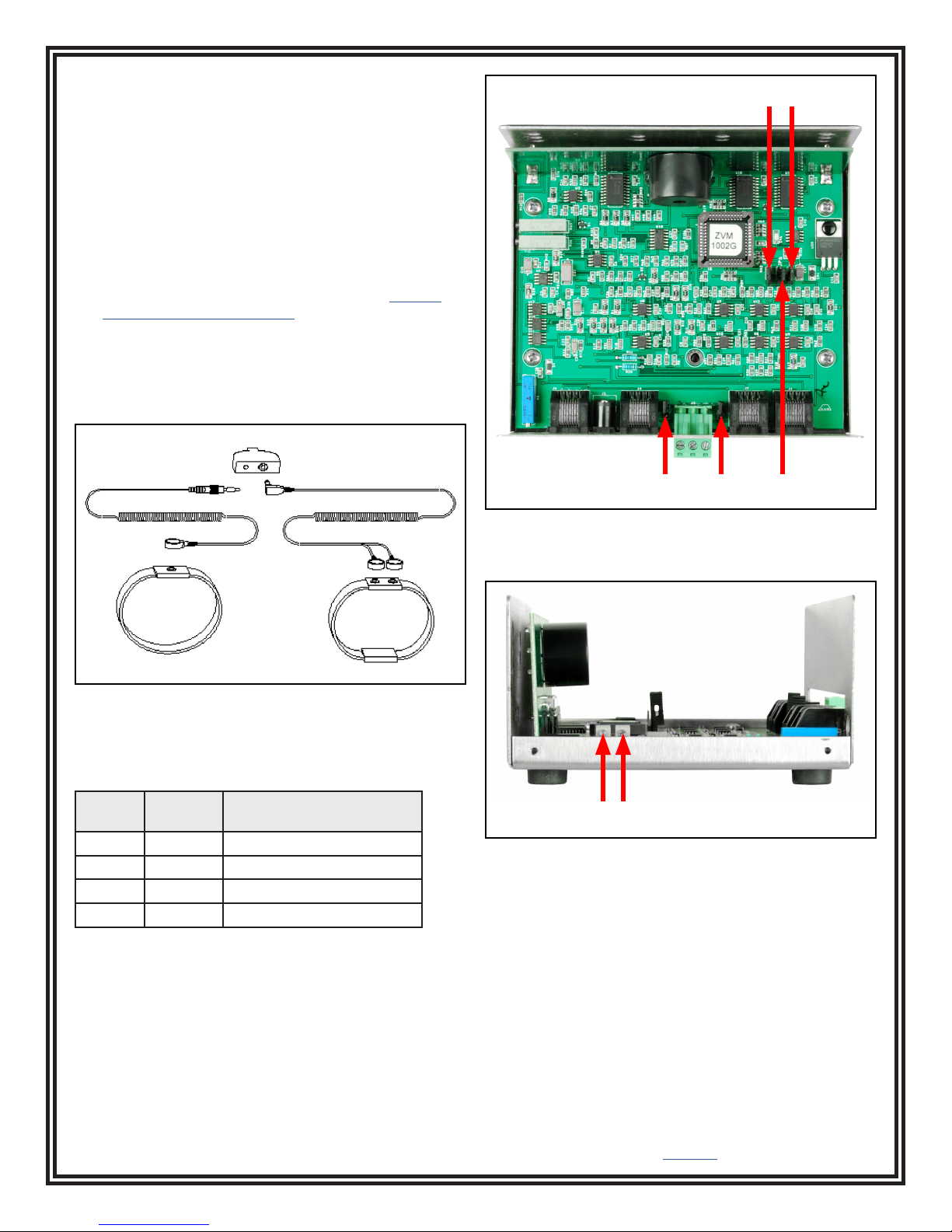
JP5 JP7
JP6JP2 JP1
Figure 5. Jumper locations
Figure 4. Connecting single-wire and dual-wire wrist
straps to the operator remote
Maintenance
JUMPER CONFIGURATIONS
Jumper Jumper
Position
JP5 Off Audible alarm enabled
JP5 On Audible alarm disabled
JP6 Off Charge detection enabled
JP6 On Charge detection disabled
Setting
WORKSURFACE MAT TEST LIMIT THRESHOLDS
MAT 2 MAT 1
Figure 6. Mat test limit potentiometers
DESCO EAST - One Colgate Way, Canton, MA 02021-1407 • (781) 821-8370 • Website: Desco.com
DESCO WEST - 3651 Walnut Avenue, Chino, CA 91710 • (909) 627-8178
TB-3078 Page 4 of 6
© 2019 DESCO INDUSTRIES INC
Employee Owned
Page 5
3.5 megohms
1. If the desired resistance is 3.5M, jumpers JP1 (MAT
1 and JP2 (MAT 2) need to be on one pin (see
Figure 5).
2. The respective potentiometers need to be adjusted
fully clockwise. The pots are located inside the unit
on the bottom board (see Figure 6).
High Resistance (10 kilohms to 3.5 megohms)
1. If the desired resistance is 10k - 3.5M, jumpers JP1
(MAT 1) and JP2 (MAT 2) need to be on one pin
(see Figure 5).
Calibration
Frequency of recalibration should be based on the
critical nature of those ESD sensitive items handled
and the risk of failure for the ESD protective equipment
and materials. In general, Desco recommends that
calibration be performed annually.
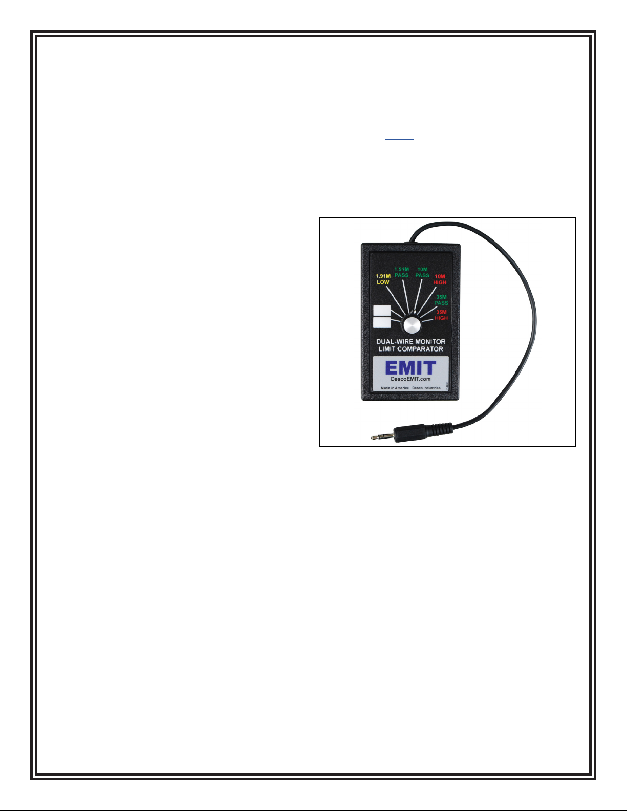
Use the EMIT 50524 Limit Comparator to perform
periodic verification (once every 6-12 months) of the
Zero Volt Monitor Monitor. The verification tester can
be used to check the test limits of the Zero Volt Monitor
without removing it from the workstation.
2. Use a resistor decade box to set the desired
resistance between the ground terminal and ground.
3. Connect the mat wire to the decade box and
connect the decade box to ground.
4. Turn the appropriate potentiometer
counter-clockwise until the GROUND LED
illuminates red and alarm sounds (see Figure 6).
5. Slowly turn the potentiometer clockwise until the
GROUND LED illuminates green.
6. Add 10% more resistance (at least 1 ohm) to the
decade box and verify that the GROUND LED
illuminates red and alarm sounds.
7. Return back to the starting resistance and confirm
that the green LED illuminates again. Repeat steps
4-7 if the monitor does not fail with the increased
resistance or return to a pass condition.
Low Resistance (<1 kilohm)
1. If the desired resistance is < 1k, jumpers JP1 (MAT
1) and JP2 (MAT 2) need to be on both pins (see
Figure 5).
2. Use a resistor decade box to set the desired
resistance between the ground terminal and ground.
See TB-6542 for more information.
Figure 7. EMIT 50524 Limit Comparator
3. Connect the mat wire to the decade box and
connect the decade box to ground.
4. Turn the appropriate potentiometer
counter-clockwise until the GROUND LED
illuminates red and alarm sounds (see Figure 6).
5. Slowly turn the potentiometer clockwise until the
GROUND LED illuminates green.
6. Add 10% more resistance (at least 1 ohm) to the
decade box and verify that the GROUND LED
illuminates red and alarm sounds.
7. Return back to the starting resistance and confirm
that the green LED illuminates again. Repeat steps
4-7 if the monitor does not fail with the increased
resistance or return to a pass condition.
DESCO WEST - 3651 Walnut Avenue, Chino, CA 91710 • (909) 627-8178
DESCO EAST - One Colgate Way, Canton, MA 02021-1407 • (781) 821-8370 • Website: Desco.com
TB-3078 Page 5 of 6
© 2019 DESCO INDUSTRIES INC
Employee Owned
Page 6

Specifications
Input Voltage and
Frequency
(External Adapter)
Operating Temperature 50 to 95 °F (10 to 35 °C)
Environmental
Requirements
Dimensions 5.6" L x 4.7" W x 2.6" H
Weight 1.6 lbs. (0.7 kg)
Operator Test Limts 1.91 megohms to 10
Worksurface Test
Limit*
Charge Detect Test
Limit
Operator Test Voltage 1.25 V, open circuit
Worksurface Test
Voltage
Country of Origin United States of America
AC/DC Power Adapter
Power Input:
100-240 VAC, 50/60 Hz
Power Output:
12 VDC @ 0.50 A
Cable Length:
6 ft. (1.8 m)
Indoor use only at altitudes
less than 6500 ft. (2 km)
Maximum relative humidity
of 80 % up to 85 °F (30 °C)
decreasing linearly to 50 %
@ 85 °F (30 °C)
(142 mm x 119 mm x 66 mm)
megohms (±10 %)
3.5 megohms (±10 %)
±1.25 VDC
200 mV, open circuit
Limited Warranty, Warranty Exclusions, Limit
of Liability and RMA Request Instructions
See the Desco Warranty -
Desco.com/Limited-Warranty.aspx
*The worksurface mat must have a conductive
layer such as Dual Layer Rubber or Dissipative
3-Layer Vinyl with conductive buried layers. Desco
workstation monitors are not recommended for use with
homogeneous matting.
ANSI/ESD S20.20 requires the use of a surface
resistance meter for periodic verification of a
worksurface's resistance-to-ground (Rtg). Constant
monitors may not be used as a substitute for this
requirement.
DESCO EAST - One Colgate Way, Canton, MA 02021-1407 • (781) 821-8370 • Website: Desco.com
DESCO WEST - 3651 Walnut Avenue, Chino, CA 91710 • (909) 627-8178
TB-3078 Page 6 of 6
© 2019 DESCO INDUSTRIES INC
Employee Owned
 Loading...