

Page 1
TECHNICAL BULLETIN TB-3037
Surface Resistance Checker
Operation and Maintenance
ESD protected area products should be tested:
A. Prior to installation to qualify for listing in user’s ESD
control plan. Approved ESD materials (see product
qualification table at ANSI/ESD S20.20-2007 Table 3
EPA ESD control items)
B. During initial installation
C. For periodic checks of installed products as part of
ANSI/ESD S20.20-2007 Compliance Verification testing
per ESD TR53.
Compliance Verification Plan
“A Compliance Verification Plan shall be established
to ensure the Organization’s fulfillment of the technical
requirements of the ESD Control Program Plan. Process
monitoring (measurements) shall be conducted in
accordance with a Compliance Verification Plan that
identifies the technical requirements to be verified, the
measurement limits and the frequency at which those
verifications shall occur. The Compliance Verification Plan
shall document the test methods and equipment used
for process monitoring and measurements. If the test
methods used by the Organization differ from any of the
standards referenced in this document, then there must
be a tailoring statement that is documented as part of the
ESD Control Program Plan. Compliance verification records
shall be established and maintained to provide evidence of
conformity to the technical requirements.
Made in America
Figure 1. Desco 19640 Surface Resistance Checker
Description
The Desco
portable battery powered checker fitted with built-in
parallel electrodes that allow for tests of material
surface resistance. This meter is designed for
quick checks of surface resistance for ESD control
applications in electronics manufacturing or handling
environment.
equipped with an automatic test voltage selector. The test
voltage will switch from 10V to 100V should the measured
resistance exceed 1 x 10E5 ohms.
and an electrode toggle switch allow for the connection
of two external 5 pound electrodes that measure
surface resistance point to point (RTT) or resistance to
equipment ground (RTG).
19640
Surface Resistance Checker is a
The Surface Resistance Checker is
Two banana jacks
The test equipment selected shall be capable of making the
measurements defined in the Compliance Verification Plan.”
(ANSI/ESDS20.20-2007 section 7.3)
Packaging
1 Surface Resistance Checker
1 9V Battery
1 Certificate of Calibration
The following accessories are available:
Item Description
19641 Pair of Test Leads
50003 5 Pound Electrodes
DESCO EAST - One Colgate Way, Canton, MA 02021-1407 • (781) 821-8370 • Fax (781) 575-0172 • Website: Desco.com
TB-3037 May 2009 Page 1 of 4
DESCO WEST - 3651 Walnut Avenue, Chino, CA 91710 • (909) 627-8178 • Fax (909) 627-7449
© 2009 DESCO INDUSTRIES INC.
Employee Owned
Page 2
Features and Components
A
TOP VIEW
B
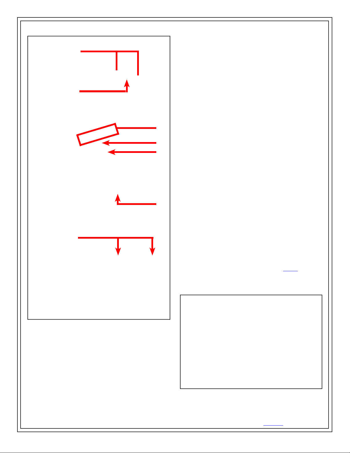
C. Resistance Measurement LEDs: The resistance is
measured in ohms and read as 10EX ±1/2 decade where X
is the range illuminated on the checker.
D. Low Battery LED: When illuminated, this LED indicates
when the battery needs to be replaced. Do not use the
Surface Resistance Checker when this LED is illuminated.
E. Test Contact: Use this contact area to make a surface
resistance measurement. Press and hold until one of the
Resistance Measurement LEDs remains illuminated.
F. Battery Compartment: Remove the cover to allow
access to the 9V battery compartment.
G. Parallel Electrodes: Be sure to position the Electrode
Toggle Switch to “INTERNAL” when choosing to make a
C
measurement using the parallel electrodes built-in on the
back of the Surface Resistance Checker.
FRONT VIEW
REAR VIEW
D
E
Operation
USING THE INTERNAL PARALLEL ELECTRODES
MEASURE RESISTANCE POINT-TO-POINT (RTT) ON
THE SURFACE
• Do not clean the surface prior to testing
• Remove all items from the surface that may interfere with
the test
• ESD sensitive devices should also be removed
F
• Place the Surface Resistance Checker on the most
commonly used portion of the surface (2” from any edge,
3” from any groundable point)
• Toggle the Electrode Switch located at the top of the
Surface Resistance Checker to “INTERNAL”
G
• Press and hold the test contact until the measurement is
displayed
• If the measurement is outside acceptable limits, clean the
surface and re-test to determine if the cause of failure is
an insulative dirt layer or the surface material.
NOTE: For worksurfaces, use Desco Item# 10435
Reztore™ Antistatic Surface and Mat Cleaner or other
silicone-free ESD cleaner. Be sure the surface is dry before
testing.
Figure 2. Surface Resistance Checker features and
components
A. Electrode Banana Jacks: Insert the test leads from the
optional 5 pound electrodes here.
B. Electrode Toggle Switch: Position the switch to the
left (“INTERNAL”) to measure using the built-in parallel
electrodes on the back of the Surface Resistance Checker.
Position the switch to the right (“EXTERNAL”) to measure
using one or two of the optional 5 pound electrodes.
DESCO WEST - 3651 Walnut Avenue, Chino, CA 91710 • (909) 627-8178 • Fax (909) 627-7449
DESCO EAST - One Colgate Way, Canton, MA 02021-1407 • (781) 821-8370 • Fax (781) 575-0172 • Website: Desco.com
TB-3037 Page 2 of 4
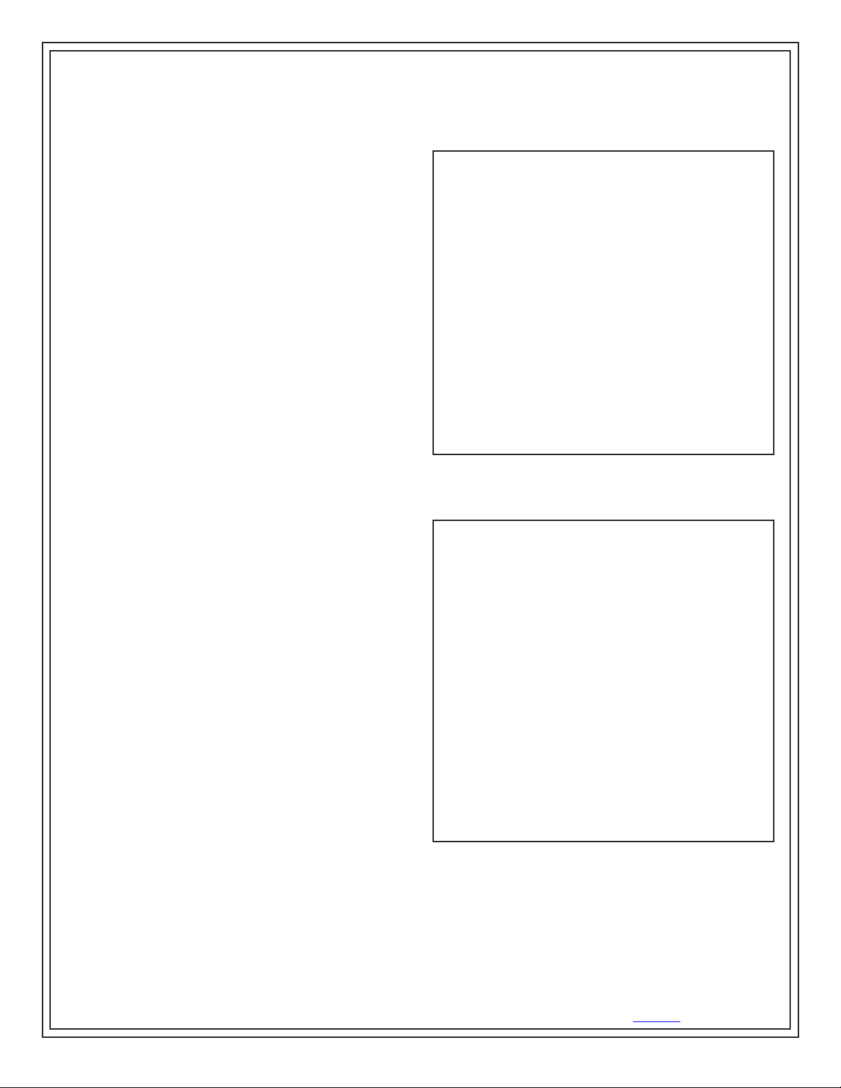
Figure 3. Using the internal parallel electrodes to measure
surface resistance
© 2009 DESCO INDUSTRIES INC.
Employee Owned
Page 3
USING THE OPTIONAL TEST LEADS AND ONE OR
TWO 5 POUND ELECTRODES
GENERAL GUIDELINES
• Use both 5 pound electrodes for RTT
• Use one 5 pound electrode and one lead to groundable
point for RTG (note: groundable points are usually snaps
installed on the material or workstation common point
ground)
• Ensure that the item being measured is electrically
isolated (i.e. placed on an insulative surface) as the
checker will measure the lowest resistance path
• Ensure that the test leads are separated as a best
practice
• When using the 5 pound electrodes:
• Place no closer than 2” from the edge of the surface
being measured
• Place no closer than 3” to any groundable point
• Place the 5 pound electrodes about 10” apart for RTT
of worksurface and 3’ for floor
• Preferred placements include: most commonly used
surface portion, most worn, center, and furthest from
groundable point.
• For RTG, connect the banana plug to groundable point
• If surface has sections (floor tiles, garment panels), for
RTT place the 5 pound electrodes on different sections
• Garments - “To maintain process control, it is imperative
that the garment be tested per ANSI/ESD STM 2.1. The
point-to-point and sleeve-to-sleeve resistance test should
be made.” (see ESD TR20.20 section 5.3.13.3.1.8
Periodic Testing)
Recommended Frequency of Periodic Checks
of Installed Products
The ESD Association lists test procedures and
troubleshooting tips in Compliance Verification ESD TR53.
Note: “The frequency of periodic testing is normally
specified in corporate operating procedures. …The
frequency of testing is driven by the amount of risk
exposure that can occur between tests. For, example, what
is the quantity of product handled between test periods?”
(See ESD Handbook ESD TR20.20)
A GUIDE FOR PERIODIC TESTING
• Worksurface, Carts, Shelves - at least quarterly (see ESD
TR20.20 section 5.3.1.13 Periodic Tests)
• Footwear - “Incoming inspection on a lot sampling basis
should be performed for all static control footwear.” (see
ESD TR20.20 section 5.3.3.4 Testing)
• Floor - “The types of monitoring and type of equipment
are considerations. In some cases, a simple electrical
resistance test with a megohmmeter may suffice. In
others, a static charge generation test may be required.”
(see ESD TR20.20 section 5.3.4.13 Performance
Monitoring)
• Seating - “The recommended electrical resistance range
for seating is less than 1 x 10E9 ohms as tested in
accordance with ANSI/ESD STM 12.1. This value should
be during acceptance testing, installation and periodically
thereafter.” (see ESD TR20.20 section 5.3.5.3 Testing)
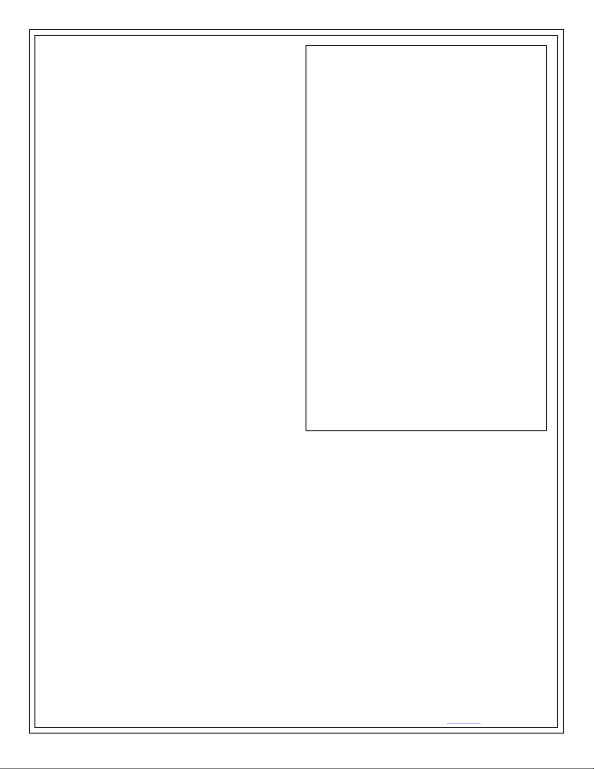
Figure 4. Using the test leads and one 5 pound electrode to
measure RTG
10”
Figure 5. Using the test leads and two 5 pound electrodes
to measure RTT
TB-3037 Page 3 of 4
DESCO EAST - One Colgate Way, Canton, MA 02021-1407 • (781) 821-8370 • Fax (781) 575-0172 • Website: Desco.com
DESCO WEST - 3651 Walnut Avenue, Chino, CA 91710 • (909) 627-8178 • Fax (909) 627-7449
© 2009 DESCO INDUSTRIES INC.
Employee Owned
Page 4
Specifications
Accuracy ±1/2 decade
Weight 0.4 lbs
Size 5.2” x 2.9” x 1.1”
Power Supply 9V alkaline battery
Maintenance
The area surrounding the cable jacks at the top end of
the meter should be wiped with a clean cloth moistened
with alcohol to remove skin oils that will accumulate and
affect the accuracy at high resistances. The frequency of
cleaning will depend on usage; once a month would be a
good starting point.
Per ANSI/ESD S4.1 “Clean the electrodes with a minimum
70% isopropanol-water solu tion.” Make sure conductive
pads are dry prior to use.
See specific product test standard for test lab specimen
cleaning instructions. Per ANSI/ESD S4.1 Worksurfaces
“The test specimens and electrodes shall be cleaned twice
with a minimum 70% isopropanol-water solution using a
clean, low-linting cloth each time.” (then conditioned for a
minimum of 72 hours).
For compliance verification testing, do not clean surfaces.
However, if any measurements lie outside acceptable
range, then clean the material’s surface and re-test.
NOTE: For worksurfaces, use Desco Item# 10435
Reztore™ Antistatic Surface and Mat Cleaner or other
silicone-free ESD cleaner. Be sure the surface is dry before
testing.
The Surface Resistance Checker requires little
maintenance, and there are no user serviceable parts. If
your unit requires service beyond cleaning the electrodes
or replacing the batteries, please contact Desco Customer
Service.
Limited Warranty
Desco expressly warrants that for a period of one (1) year from the
date of purchase Desco Surface Resistance Checkers will be free
of defects in material (parts) and workmanship (labor). Within the
warranty period, a credit for purchase of replacement Desco Surface
Resistance Checkers, or, at Desco’s option, the Surface Resistance
Checker will be repaired or replaced free of charge. If product credit
is issued, the amount will be calculated by multiplying the unused
portion of the expected one year life times the original unit purchase
price. Call our Customer Service Department at 909-627-8178 (Chino,
CA) or 781-821-8370 (Canton, MA) for a Return Material Authorization
(RMA) and proper shipping instructions and address. Please include
a copy of your original packing slip, invoice, or other proof of date of
purchase. Any unit under warranty should be shipped prepaid to the
Desco factory. Warranty replacements will take approximately two
weeks.
If your unit is out of warranty, call our Customer Service Department
at 909-627-8178 (Chino, CA) or 781-821-8370 (Canton, MA) for a
Return Material Authorization (RMA) and proper shipping instructions
and address. Desco will quote repair charges necessary to bring your
unit up to factory standards.
Warranty Exclusions
THE FOREGOING EXPRESS WARRANTY IS MADE IN LIEU
OF ALL OTHER PRODUCT WARRANTIES, EXPRESSED AND
IMPLIED, INCLUDING MERCHANTABILITY AND FITNESS
FOR A PARTICULAR PURPOSE WHICH ARE SPECIFICALLY
DISCLAIMED. The express warranty will not apply to defects or
damage due to accidents, neglect, misuse, alterations, operator error,
or failure to properly maintain, clean or repair products.
Limit of Liability
In no event will Desco or any seller be responsible or liable for any
injury, loss or damage, direct or consequential, arising out of the
use of or the inability to use the product. Before using, users shall
determine the suitability of the product for their intended use, and
users assume all risk and liability whatsoever in connection therewith.
TB-3037 Page 4 of 4
DESCO EAST - One Colgate Way, Canton, MA 02021-1407 • (781) 821-8370 • Fax (781) 575-0172 • Website: Desco.com
DESCO WEST - 3651 Walnut Avenue, Chino, CA 91710 • (909) 627-8178 • Fax (909) 627-7449
© 2009 DESCO INDUSTRIES INC.
Employee Owned
 Loading...