

Desco 19492 Installation Manual
TECHNICAL BULLETIN TB-3041
Ionization Test Kit
Operation and Maintenance
Charged insulators in the ESD protected area can
adversely impact quality, productivity, and reliability.
“When any object becomes electrostatically charged,
there is an electrostatic eld associated with that charge.
If an ESDS (ESD sensitive) device is placed in that
electrostatic eld, a voltage may be induced on the
device. If the device is then momentarily grounded, a
transfer of charge from the device occurs as a CDM
(Charged Device Model) event. If the device is removed
from the region of the electrostatic eld and grounded
again, a second CDM event will occur as charge (of
opposite polarity from the rst event) is transferred from
the device.” (ESD Handbook ESD TR20.20 section
2.7.5 Field Induced Discharges)
Compliance verication should include periodic checks
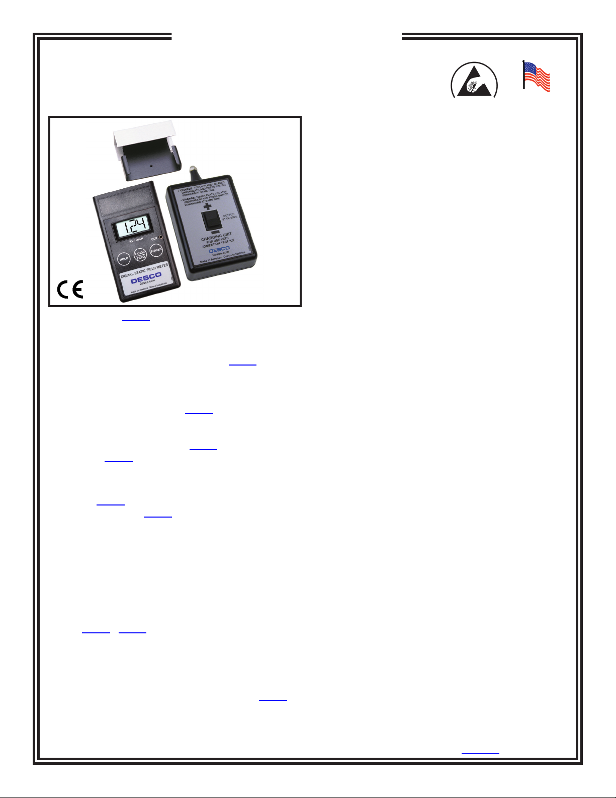
Figure 1. Desco 19493 Ionization Test Kit
Description
The Desco Ionization Test Kit allows the 19492 Digital
Static Field Meter to be used to measure the offset
voltage (balance) and charge decay of ionization
equipment. The Test Kit also includes a Charger used to
place a ±1000V charge on the 19498 Conductive Plate,
making it possible to also measure the discharge times
of air ionization equipment per ANSI/ESD SP3.3 Periodic
Verication of Air Ionizers. The 19493 Ionization Test Kit
includes the 19492 Digital Static Field Meter, providing a
highly portable and cost effective means of verifying the
performance of a wide variety of ionization equipment.
Note: The 19492 Digital Static Field Meter is designed to
operate only with the 19493 Ionization Test Kit. It is not
compatible with other brands.
Although not as accurate, the Desco Ionization Test Kit
has been designed to make measurements that
correspond to those made by using a charged plate
analyzer and ANSI/ESD S3.1. The Ionization Test Kit
provides convenience and portability to test per ANSI/
ESD SP3.3 Periodic Verication of Air Ionizers or
Compliance Verication ESD TR53. We recommend
EMIT’s 50555 / 50561 Charged Plate Analyzer if precise
measurements are required.
The Ionization Test Kit includes a slide-on isolated
Conductive Plate, a ±1000 volt Charger and a durable
thermoplastic carrying case with custom cut-outs for all
of the above components along with the model 19492
Digital Static Field Meter.
with a static eld meter to determine if high
charging material is present in the ESD protected area.
All packaging and other materials that may be
electrostatic generative to 2,000 volts must be kept a
minimum of 12" from ESD sensitive items at all times. It
is proper to rub an item and measure that it can charge.
“In order to mitigate eld-induced CDM (Charged Device
Model) damage, the ESD program shall include a plan
for the handling of process-required insulators. If the
eld exceeds 2,000 volts/inch, steps shall be taken to
either:
A. Separate the insulator from the ESD-sensitive device
by a distance of 30 cm (12 inches); or
B. Use ionization or other charge mitigating techniques
to neutralize the charge.” (ANSI/ESDS20.20 section
8.3)
Other steps that can be taken are to remove the item
from the ESD protected area, periodically coat with a
topical antistat, or replace with a static control protective
version of the item.
Packaging
1 Digital Static Field Meter
1 Conductive Plate
1 Charger
2 9V Alkaline Batteries
1 Data Output Cord
1 Carrying Case
1 Certicate of Calibration
Made in America
TB-3041 Page 1 of 6
DESCO EAST - One Colgate Way, Canton, MA 02021-1407 • (781) 821-8370 • Fax (781) 575-0172 • Website: Desco.com
DESCO WEST - 3651 Walnut Avenue, Chino, CA 91710 • (909) 627-8178 • Fax (909) 627-7449
Rev. June 2009
© 2009 DESCO INDUSTRIES, INC.
Employee Owned
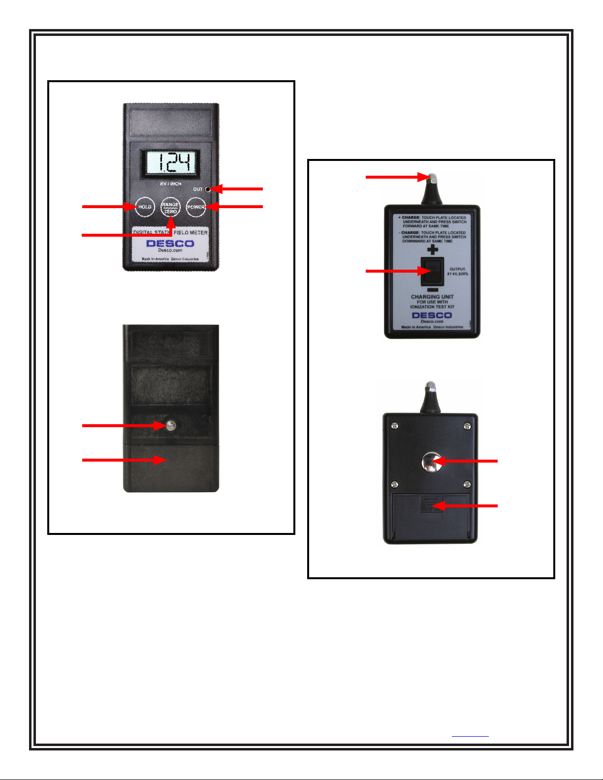
Features and Components
DIGITAL STATIC FIELD METER
D. POWER Button: Press to turn the unit ON and OFF.
E. 4mm Stud: Use this stud to ground the Meter using
a 4mm ground cord (not provided - any standard single
wire wrist strap cord can be used).
F. Battery Cover: Slide the cover down to open the 9V
battery compartment.
CHARGER
A
C
A
B
D
B
FRONT VIEW
FRONT VIEW
E
F
C
BACK VIEW
Figure 2. Digital Static Field Meter features and
components
A. HOLD Button: Press to freeze the reading on the
display. Press again to return to normal measurement
operation.
B. RANGE / ZERO Button: Press to select the
measurement range. Press and hold to zero the Meter.
C. Analog Output Jack: A low-voltage replica of the
measured voltage is provided at this output. The voltage
at this output is 1/1000th (±2 kV range) or 1/10,000 (±20
kV range) of the measured voltage.
DESCO WEST - 3651 Walnut Avenue, Chino, CA 91710 • (909) 627-8178 • Fax (909) 627-7449
DESCO EAST - One Colgate Way, Canton, MA 02021-1407 • (781) 821-8370 • Fax (781) 575-0172 • Website: Desco.com
TB-3041 Page 2 of 6
D
BACK VIEW
Figure 3. Charger features and components
A. Output Contact: The output contact is connected to
an internal power source. When the touch plate located
underneath the unit is connected to ground, the output
contact will provide a charge of the indicated polarity.
The charger is designed so that an operator can press
the rocker switch and touch the plate simultaneously
with the ngers of the same hand.
© 2009 DESCO INDUSTRIES, INC.
Employee Owned
 Loading...