

Page 1
TECHNICAL BULLETIN TB-3076.E
EUROPE
Digital Surface Resistance Meter Kit
Installation, Operation and Maintenance
The Surface Resistance Meter Kit (or its Meter) is referenced
and designed to be used to make measurements in
accordance with the test procedures in:
• Working surfaces, storage racks, trolleys and seating IEC 61340-2-3
• Flooring - IEC 61340-4-1
• Garments - ANSI/ESD STM2.1 Garments
• Person/footwear / flooring system - IEC 61340-4-5
“A compliance verication plan shall be established to
ensure the organization’s fullment of the requirements
of the plan. Process monitoring (measurements) shall be
conducted in accordance with a compliance verication
plan that identies the technical requirements to be
veried, the measurement limits and the frequency at
which those verications shall occur. The compliance
verication plan shall document the test methods
used for process monitoring and measurements. If the
organization uses dierent test methods to replace
those of this standard, the organization shall be able
to show that the results achieved correlate with the
referenced standards. Where test methods are devised
Figure 1. Desco Digital Surface Resistance Meter Kit
Description
The Desco 19290 Digital Surface Resistance Meter
Kit is an instrument designed to measure resistance
point-to-point (Rtt) or surface to ground (Rtg).
Its test functions include:
• Resistance measurement accuracy of ±10 %
(±20 % accuracy for 1 x 10¹² ohms and greater)
• Resistance range of <1 x 10³ ohms to >1 x 10¹²
ohms
• Under load voltages of 10 and 100 volts ±5 %
• Electrification period of approximately 15 seconds
The Digital Surface Resistance Meter also measures
ambient temperature and relative humidity. Up to 100
measurements may be stored and recalled from the
meter's internal memory. This includes the resistance
value, temperature, relative humidity and test voltage at
the time of the measurement.
for testing items not covered in this standard, these shall
be adequately documented including corresponding
test limits. Compliance verication records shall be
established and maintained to provide evidence of
conformity to the technical requirements. The test
equipment selected shall be capable of making the
measurements dened in the compliance verication
plan.” (EN 61340-5-1 clause 5.2.4 Compliance
verication plan)
Reference Literature
In addition to those noted above:
EN 61340-5-1 Electrostatics and PD CLC/TR 61340-5-2 User
Guide Electrostatics
These documents can be obtained from from British
Standards at www.bsigroup.com.
Made in the
United States of America
DESCO EUROPE - 2A DUNHAMS LANE, LETCHWORTH, HERTFORDSHIRE, SG6 1BE, UK
Phone: +44 (0) 1462 672005 • E-mail: [email protected], Website: DescoEurope.com
TB-3076.E Page 1 of 8
October 2018
© 2018 DESCO INDUSTRIES INC
Employee Owned
Page 2
The Digital Surface Resistance Meter and its
accessories are available in the following item numbers:
Item Description
19290 Digital Surface Resistance Meter Kit
19291 Digital Surface Resistance Meter
19292 Carrying Case
19293 Electrode Spacers, 25 cm and 91 cm
19294 Test Leads
19295 Handheld Electrode
19296 Measurement Location Labels, 25 Pack
222634 Replacement 2.27 kg Electrodes
50004 Replacement T-Handles for 2.27 kg
Electrodes
222002 Concentric Ring Probe
Packaging
19290 Digital Surface Resistance Meter Kit
1 Digital Surface Resistance Meter
2 Test Leads, 1.5 m Length
2 2.27 kg Electrodes
1 Electrode Spacer, 25 cm
1 Electrode Spacer, 91 cm
4 AA Alkaline Batteries
1 Ground Plug Adapter
1 Gator Clip
25 Measurement Location Labels
1 Plastic Carrying Case
1 Certificate of Calibration
19291 Digital Surface Resistance Meter
1 Digital Surface Resistance Meter
4 AA Alkaline Batteries
1 Certificate of Calibration
Figure 3. Desco 19291 Digital Surface Resistance Meter
Figure 2. Desco 19290 Digital Surface Resistance Meter
Kit
DESCO EUROPE - 2A DUNHAMS LANE, LETCHWORTH, HERTFORDSHIRE, SG6 1BE, UK
Phone: +44 (0) 1462 672005 • E-mail: [email protected], Website: DescoEurope.com
TB-3076.E Page 2 of 8
© 2018 DESCO INDUSTRIES INC
Employee Owned
Page 3
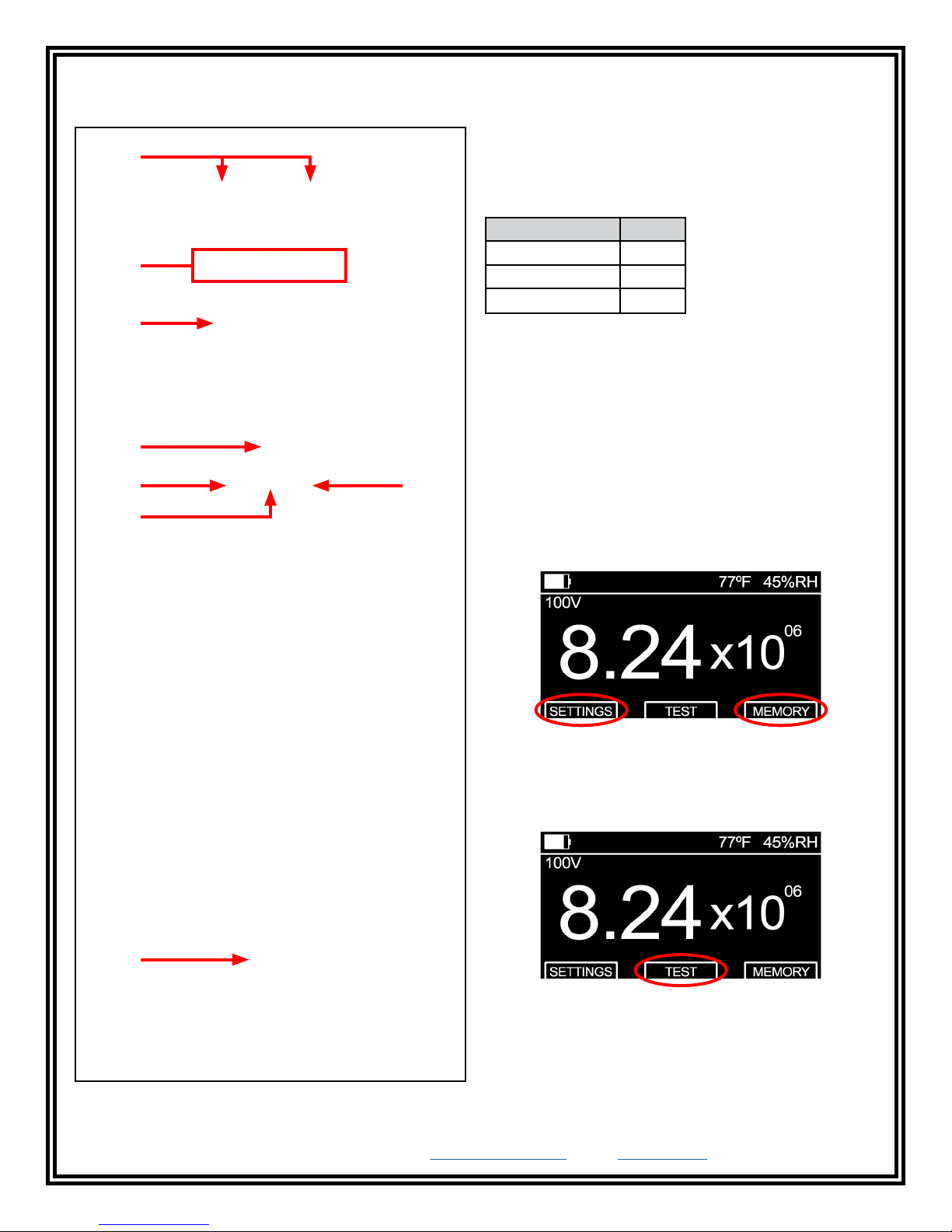
Features and Components
Digital Surface Resistance Meter
A
B
C
D
A. Test Jacks: The shielded black test lead’s male
SMA connector connects into the meter's female SMA
connector, and the red test lead’s banana plug connects
into the meter's banana jack.
B. Exponent LEDs: These LEDs indicate the surface
resistance exponent value. They are colour coded for
resistance decade quick checks.
Exponent Colour
<3, 3 Yellow
4, 5, 6, 7, 8, 9, 10 Green
11, 12, >12 Red
(i.e. 8 = 10⁸ ohms or 100,000,000 ohms).
C. OLED Display: Displays the temperature, relative
humidity, battery life, test voltage and resistance
measurement.
D. Power Switch: Slide the switch to the left to power
the meter OFF. Slide the switch to the right to power the
meter ON.
E
E
E. Black Pushbuttons: Each black pushbutton
corresponds to the prompts on the bottom-left and
F
bottom-right of the display. These buttons are used to
access the Settings and Memory Recall menus and
scroll up and down between menu options.
F. Red Pushbutton: Corresponds to the prompts
located in the bottom-centre of the display. This button
is used to perform tests and select menu options. Press
and hold this button when in the Settings and Memory
Recall menus to exit and return to the home screen.
G
Figure 4. Digital Surface Resistance Meter features and
components
DESCO EUROPE - 2A DUNHAMS LANE, LETCHWORTH, HERTFORDSHIRE, SG6 1BE, UK
Phone: +44 (0) 1462 672005 • E-mail: [email protected], Website: DescoEurope.com
TB-3076.E Page 3 of 8
G. Battery Compartment: Open this compartment to
install the four AA alkaline batteries needed to power
the meter. Replace the batteries once the battery icon
on the display is empty.
© 2018 DESCO INDUSTRIES INC
Employee Owned
Page 4
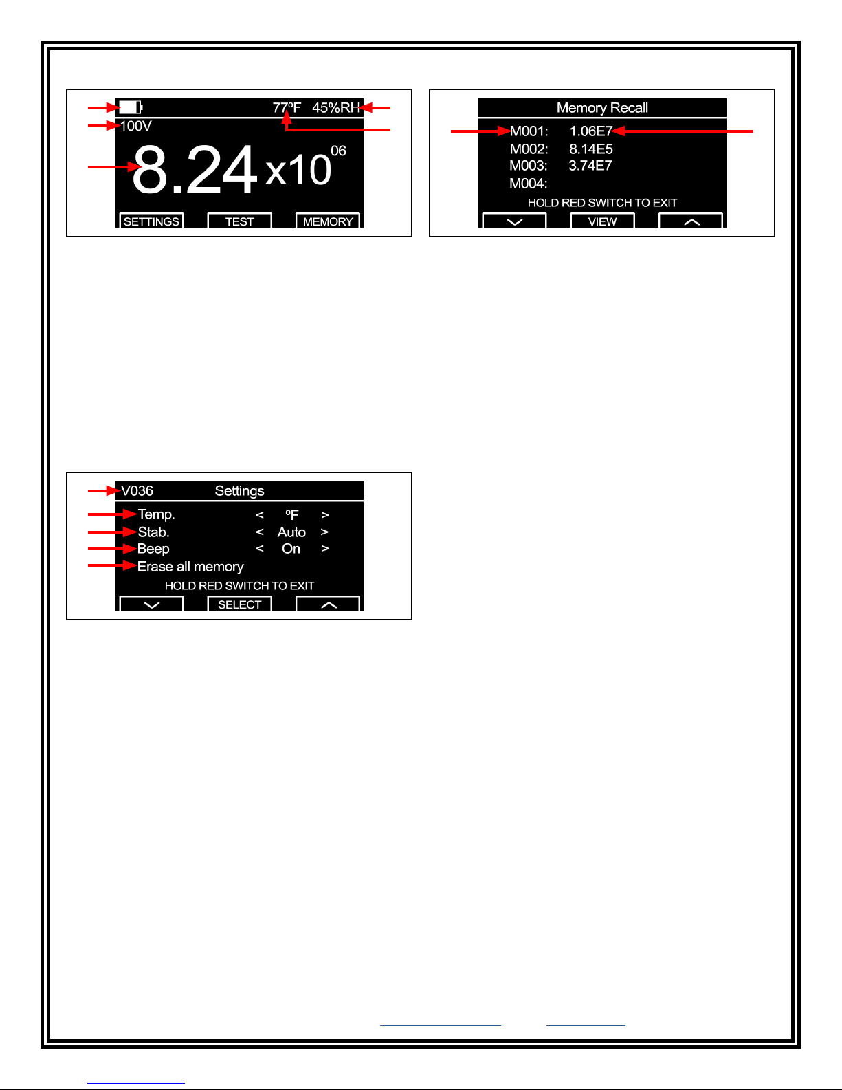
Home / Test Results Screen Memory Recall Menu
H
J
L
I
K
Figure 5. Home / Test Results screen
H. Battery Life Indicator: Displays the approximate life
of the meter's 4 AA alkaline batteries.
I. Relative Humidity: Displays the relative humidity.
J. Test Voltage: Displays the test voltage used to
complete the measurement.
K. Temperature: Displays the ambient temperature.
L. Resistance Measurement: Displays the resistance
measurement in ohms (Ω).
Settings Menu
M
N
O
P
Q
Figure 6. Settings menu
M. Firmware Revision: Displays the meter's firmware
revision.
N. Temperature: Sets the unit of measurement for
temperature to either Fahrenheit (ºF) or Celsius (ºC).
O. Stabilisation Mode: Sets the meter's electrification
period setting to either Auto and Fixed Stabilisation.
Auto - Enables a 15-second electrification period when
the measured resistance is 1 x 10¹⁰ ohms or greater to
maintain test accuracy.
Fixed - Complies with EN 61340-2-3 and enables a
15-second electrification period when the measured
resistance is 1 x 10⁶ ohms or greater.
P. Beep: Enables and disables the audible beep when
the meter's pushbuttons are pressed.
Q. Erase all memory: Erases all stored measurement
transactions saved in the meter's memory.
R S
Figure 7. Settings menu
R. Memory Slot Number: Indicates the memory slot
number.
S. Resistance Measurement: Indicates the resistance
measurement value for the respective memory slot.
Operation
General Guidelines
Use both 2.27 kg electrodes for Resistance
Point-to-Point (Rtt) measurements.
Use one 2.27 kg electrode, and connect the black
test lead to ground for Resistance-to-Ground (Rtg)
measurements.
Ensure that the item being measured is electrically
isolated (placed on an insulative surface). The meter will
measure the lowest resistance path.
Minimise crossing the test leads when possible.
When using 2.27 kg electrodes:
• Place them no closer than 5 cm from the edge of
the surface being measured.
• Place them no closer than 8 cm to any groundable
point.
• Place them about 25 cm apart from each other for
Rtt measurements of a worksurface.
• Place them about 91 cm apart from each other for
Rtt measurement of a floor.
Preferable electrode placements include:
• Most commonly used area of a surface
• Most worn area
• Centre of surface
• Furthest area from a grounded point
If the surface to be measured has sections (i.e. floor
tiles, garment panels), place the 2.27 kg electrodes on
different sections for Rtt measurements.
Clean the material’s surface for test lab measurements,
but do not clean the surface for materials that are
already installed. Only clean and re-test the installed
material if failure occurs.
DESCO EUROPE - 2A DUNHAMS LANE, LETCHWORTH, HERTFORDSHIRE, SG6 1BE, UK
Phone: +44 (0) 1462 672005 • E-mail: [email protected], Website: DescoEurope.com
TB-3076.E Page 4 of 8
© 2018 DESCO INDUSTRIES INC
Employee Owned
Page 5
Measure Resistance-to-Ground (Rtg)
Test Procedure in accordance with
IEC 61340-2-3
and EN 61340-5-1 Table 3 Note 2 “The test methods in
the compliance verification column refer to the basic test
procedure only. It is not expected that the test method will be
followed in its entirety.”
1. Do not clean the surface.
2. Remove from the surface only those items that
might interfere with the test. ESD sensitive devices
shall also be removed.
3. Connect the black test lead to a grounded point.
4. Connect the red test lead to one 2.27 kg electrode,
and place the electrode on the furthest convenient
point on the surface.
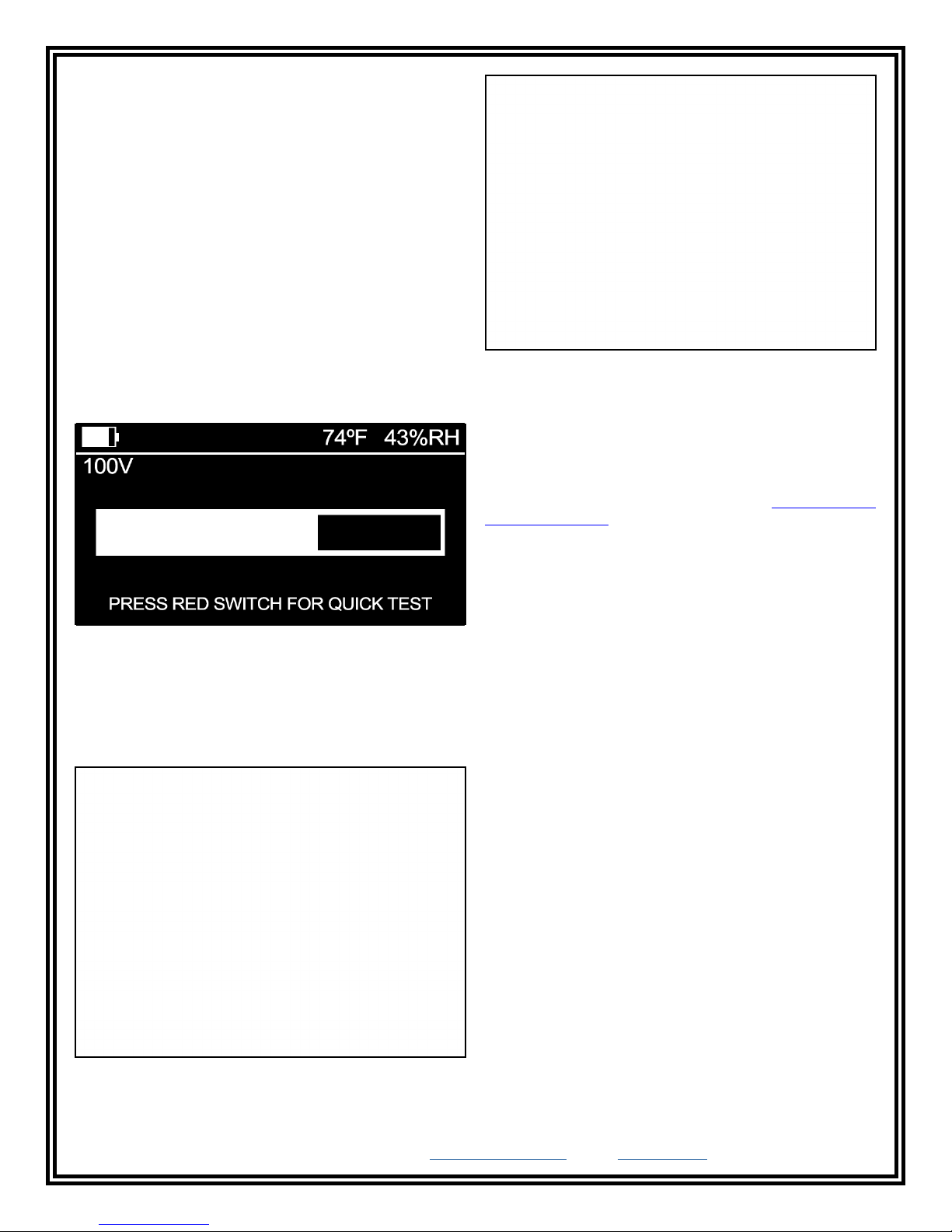
5. Push the red pushbutton to perform a measurement.
Should the 15-second electrification period appear,
it may be bypassed by pushing the red pushbutton
a second time.
6. Push the right black pushbutton to save the
measurement, and apply an included measurement
location label if desired.
7. Perform additional measurements by placing the
electrode on the most commonly used or worn area.
Figure 8. Measuring the Resistance-to-Ground (Rtg) of a
worksurface mat
Figure 10. Using the Desco 19295 Handheld Electrode
to measure Floor Materials and Footwear - Resistance
Measurement in Combination with a Person
(IEC 61340-4-5)
Figure 11. Using the Desco 19295 Handheld Electrode
Figure 9. Applying a measurement location label to the
edge of a workstation
DESCO EUROPE - 2A DUNHAMS LANE, LETCHWORTH, HERTFORDSHIRE, SG6 1BE, UK
Phone: +44 (0) 1462 672005 • E-mail: [email protected], Website: DescoEurope.com
TB-3076.E Page 5 of 8
© 2018 DESCO INDUSTRIES INC
Employee Owned
Page 6
Measure Resistance Point-to-Point (Rtt) on the
Surface
1. Do not clean the surface.
2. Remove from the surface only those items that
might interfere with the test. ESD sensitive devices
shall also be removed.
3. Connect both test leads to both 2.27 kg electrodes,
and place the electrodes on the most commonly
used area of the surface. Use the 25 cm electrode
spacer to space them 25 cm apart from each other.
The electrodes should also be 5 cm away from any
edge and 8 cm away from any grounded point. If the
most used area is not obvious, use two points near
the center of the surface.
4. Push the red pushbutton to perform a measurement.
Should the 15-second electrification period appear,
it may be bypassed by pushing the red pushbutton
a second time.
Figure 12. Electrication period timer
5. Push the right black pushbutton to save the
measurement if desired.
6. Perform additional measurements by placing the
electrode on the most commonly used or worn area.
Figure 13. Measuring the Resistance Point-to-Point (Rtt)
of oor materials
Maintenance
The Digital Surface Resistance Meter requires little
maintenance. There are no user serviceable parts. If the
meter requires service beyond cleaning the electrodes
or replacing the batteries, please contact Desco Europe
Customer Service.
Battery Replacement
Replace the batteries once the battery life indicator
is empty. Open the compartment located on the back
of the meter to replace the batteries. The meter uses
four AA alkaline batteries. Ensure that the batteries’
polarities are oriented in the correct fashion to avoid any
possible circuit damage.
Cleaning the Digital Surface Resistance Meter
The area surrounding the test jacks at the top end of the
meter should be wiped with a clean, isopropanol-alcohol
moistened cloth to remove skin oils that will accumulate
and affect the meter’s accuracy at high resistances.
The frequency of cleaning will depend on usage. Desco
Europe recommends cleaning this area once a month.
Cable jackets should also be cleaned in this fashion.
Figure 12. Measuring the Resistance Point-to-Point (Rtt)
of a oor tile
DESCO EUROPE - 2A DUNHAMS LANE, LETCHWORTH, HERTFORDSHIRE, SG6 1BE, UK
Phone: +44 (0) 1462 672005 • E-mail: [email protected], Website: DescoEurope.com
TB-3076.E Page 6 of 8
Cleaning the 2.27 kg Electrodes
Clean the electrodes with a minimum 70 % isopropanol-water
solution. Make sure the 2.27 kg electrodes’ conductive pads
are dry prior to use.
© 2018 DESCO INDUSTRIES INC
Employee Owned
Page 7
Calibration
Frequency of recalibration should be based on the
critical nature of those ESD sensitive items handled and
the risk of failure for the ESD protective equipment and
materials. In general, Desco Europe recommends that
calibration be performed annually.
Calibration Verification Procedure
1. Use only the test leads that were supplied with the
meter.
2. Use 99 % isopropyl alcohol to clean the two test
jacks located at the top of the meter. Oil from
human fingers can affect the accuracy of the meter.
In-house calibration can be performed by using
±1 % tolerance resistors in each of the meter's decade
ranges. Connect the resistors to the test leads using
clips and record the meter’s display. Minimise crossing
the test leads when possible. Contact Desco Europe
Customer Service should adjustments be necessary.
Special equipment is required to adjust the meter.
Required Equipment
• Digital Multimeter (±1.25 % accuracy @10 VDC and
100 VDC)
• Resistance Decade Box with a range of 10³ to 1012
ohms (±2 % accuracy @ 10³ to 1010 ohms; ±5 %
accuracy @ 1011 to 1012 ohms)
• Thermometer (±1 °F accuracy)
• Relative Humidity Meter (±2 % accuracy)
• 99 % Isopropyl Alcohol and Cleaning Wipes
Setup
• Test Area - needs to be free of any high voltage
transformers or power supplies and away from any
type of fluorescent lighting or high power lighting.
• Worksurface - needs to be covered with a
grounded conductive mat at 1.0 x 10³ or less.
• Technician - needs to be connected to equipment
ground with a 0 ohm resistor in the ground cord.
• Decade Box - needs to be connected to equipment
ground.
Normalisation of the Meter
The temperature inside the testing area needs to be
75 °F ±3 °F (23.9 °C ±1.7 °C) at 40 % to 60 % relative
humidity. The meter needs to stay at a temperature of
75 °F ±3 °F (23.9 °C ±1.7 °C) for approximately 1 hour
for proper readings. The meter cannot be normalised
inside objects, enclosed boxes, containers or cases.
The temperature inside an enclosed case will differ
from the outside temperature. These cases will act as
insulators. The meter must remain stationary in the
testing area for about 1 hour without any significant
changes to the temperature.
NOTE: Accuracy is measured after normalising the
meter for a minimum of 1 hour.
3. Connect the test leads to the test jacks located at
the top of the meter. Connect the opposite end of
the test leads to a DC voltmeter.
4. Press the red pushbutton. The measured voltage
should start at 10 V ±5 % and increase to 100 V
±5 % at the end of the test cycle.
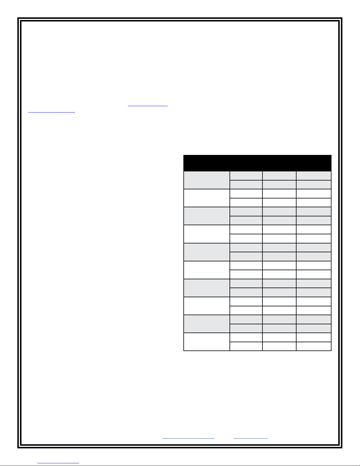
5. Connect the test leads to the Resistance Decade
Box. Apply the load resistance values indicated in
the table below. The meter should display accuracy
within ±10 % of the loaded resistance value.
Load
Resistance (Ω) Accuracy
1 x 10
1 x 10
1 x 10
1 x 10
1 x 10
1 x 10
1 x 10
1 x 10
1 x 10
1 x 10
12
11
10
9
8
7
6
5
4
3
+20 % 1.20 x 10
-20 % 8.00 x 10
+10 % 1.10 x 10
-10 % 9.00 x 10
+10 % 1.10 x 10
-10 % 9.00 x 10
+10 % 1.10 x 10
-10 % 9.00 x 10
+10 % 1.10 x 10
-10 % 9.00 x 10
+10 % 1.10 x 10
-10 % 9.00 x 10
+10 % 1.10 x 10
-10 % 9.00 x 10
+10 % 1.10 x 10
-10 % 9.00 x 10
+10 % 1.10 x 10
-10 % 9.00 x 10
+10 % 1.10 x 10
-10 % <1.0 x 10
Display
Value
Exponent
12
11
11
10
10
09
09
08
08
07
07
06
06
05
05
04
04
03
03
03
LED
12
11
11
10
10
9
9
8
8
7
7
6
6
5
5
4
4
3
3
<3
DESCO EUROPE - 2A DUNHAMS LANE, LETCHWORTH, HERTFORDSHIRE, SG6 1BE, UK
Phone: +44 (0) 1462 672005 • E-mail: [email protected], Website: DescoEurope.com
TB-3076.E Page 7 of 8
© 2018 DESCO INDUSTRIES INC
Employee Owned
Page 8
Specifications
Resistance Ranges 1 x 10³ to 1 x 10⁶ ohms @ 10
Volts, complies with
EN 61340-2-3
1 x 10⁶ to 1 x 10¹² ohms @
100 Volts, complies with
EN 61340-2-3
Resistance Accuracy
(@ 23 ºC, 40 % R.H.)
Temperature Accuracy ±10 %
Relative Humidity
Accuracy
Power Supply 4 AA alkaline batteries
Battery Life Approximately 1,500
Display OLED, 2.7" diagonal, 128 x
Memory Capacity 100 measurements
Operating Temperature 41 ºF to 85 ºF (5 ºC to 30 ºC)
Environmental
Requirements
Dimensions
(meter)
Dimensions
(carrying case)
Weight
(meter with batteries)
Weight
(populated carrying
case)
Country of Origin United States of America
Resistance measurements
within ±10 % (±20 %
accuracy for 1 x 10
12
ohms
and greater), complies with
EN 61340-2-3. Under load
voltages of 10 Volts ±5 %
and 100 Volts ±5 % exceeds
requirements of
EN 61340-2-3
±10 integers
measurements
64 pixel resolution
Indoor use only at altitudes
less than 6500 ft. (2 km)
Maximum relative humidity of
80 % up to 85 °F (30 °C)
3.94" x 8.27" x 1.26"
(100 mm x 210 mm x 32 mm)
15.0" x 14.5" x 3.5"
(381 mm x 368 mm x 89 mm)
0.9 lbs (0.4 kg)
13.0 lbs (5.9 kg)
Limited Warranty, Warranty Exclusions, Limit
of Liability and RMA Request Instructions
See the Desco Europe Warranty -
DescoEurope.com/Limited-Warranty.aspx
DESCO EUROPE - 2A DUNHAMS LANE, LETCHWORTH, HERTFORDSHIRE, SG6 1BE, UK
Phone: +44 (0) 1462 672005 • E-mail: [email protected], Website: DescoEurope.com
TB-3076.E Page 8 of 8
© 2018 DESCO INDUSTRIES INC
Employee Owned
 Loading...