

Page 1
TECHNICAL BULLETIN TB-3073
Combo Tester X3
Installation, Operation and Maintenance
The Combo Tester X3 and its accessories are available
as the following item numbers:
Item Description
19278 Combo Tester X3
19279 Combo Tester X3 with Stand
19255 Stand, for Combo Tester X3
50755 ESD Glove Test Fixture
50424 Limit Comparator
19262 Power Adapter, 100-240VAC Input, 12VDC
0.5A Output, All Plugs
50406 Replacement Dual Foot Plate
Per ANSI/ESD S20.20 section 7.3 “A Compliance
Verification Plan shall be established to ensure the
Organization’s fulfillment of the technical requirements
of the ESD Control Program Plan. Process monitoring
(measurements) shall be conducted in accordance
with a Compliance Verification Plan that identifies the
Figure 1. Desco Combo Tester X3 and Dual Foot Plate
Description
The Desco Combo Tester X3 verifies the functionality
of an operator’s wrist strap and footwear. It determines
if an operator’s wrist strap and footwear will function
correctly. The operator’s wrist strap and footwear will
test simultaneously with no need for separate tests.
Green lights indicate that the wrist strap and footwear
are passing. Red lights and an audible alarm indicate
when the wrist strap and/or footwear (left or right) are
failing. If failure occurs, the tester will also display if the
grounding device’s resistance is too low or too high.
The Combo Tester X3 features a reliable and durable
solid-state switch which replaces the traditional
mechanical test switch with a spring and moving parts.
The outer and inner portions of the solid-state switch are
designed to be bridged by a person’s skin. The Combo
Tester X3 is compatible with both single-wire and
dual-wire wrist straps.
The factory test limits are set to:
Wrist Straps: 750 kilohms and 10 megohms
Footwear: 750 kilohms and 35 megohms
(See page 3 for alternate test limit settings)
Each Combo Tester X3 is calibrated with accepted
procedures and standards traceable to the National
Institute of Standards and Technology (NIST) and
includes a NIST certificate.
technical requirements to be verified, the measurement
limits and the frequency at which those verifications
shall occur. The Compliance Verification Plan shall
document the test methods and equipment used for
process monitoring and measurements. … The test
equipment selected shall be capable of making the
measurements defined in the Compliance Verification
Plan.”
Per ANSI/ESD S1.1 Annex A.3 Frequency of System
Testing “The wrist strap system should be tested daily to
ensure proper electrical resistance.”
Per ESD Handbook ESD TR20.20 section 5.3.2.4.2
Additional User Wrist Strap Testing “Proper testing of
the wrist strap includes the resistance of the groundable
point on the end of the cord, the cord itself, the resistor,
the cord-to-cuff snap connector, the resistance of the
interface of the cuff, the cuff/wrist interface, and the
resistance of the person between the wrist and the hand
that contacts the test electrode.”
Per ESD Handbook ESD TR20.20 section 5.3.2.2.2
Wrist Strap Ground Cord “At first glance, the ground
cord appears to be a relatively simple assembly.
However, the design requirements are considerable,
given the wide range of user applications and the
durability requirements of constant tugging, flexing,
and dragging over the edge of workstation tops and
equipment chassis.”
Made in the
United States of America
DESCO EAST - One Colgate Way, Canton, MA 02021-1407 • (781) 821-8370 • Website: Desco.com
TB-3066 Page 1 of 8
December 2017
DESCO WEST - 3651 Walnut Avenue, Chino, CA 91710 • (909) 627-8178
© 2017 DESCO INDUSTRIES, INC.
Employee Owned
Page 2
“Compliance verification should be performed prior to
each use (daily, shift change, etc.). The accumulation
of insulative materials may increase the foot grounder
system resistance. If foot grounders are worn outside
the ESD protected area testing for functionality
before reentry to the ESD protected area should be
considered.” (ESD SP9.2 APPENDIX B - Foot Grounder
Usage Guidance)
“Compliance verification records shall be established
and maintained to provide evidence of conformity to the
technical requirements.” (ANSI/ESD S20.20 section 7.3)
Packaging
19278 COMBO TESTER X3
1 Combo Tester X3
1 Dual Foot Plate
1 Power Adapter, 12VDC, with interchangeable plugs
(North America, UK/Asia, Europe)
1 Foot Plate Cord, 6'
1 Ground Cord
1 Certificate of Calibration
A. Test Limit DIP Switch: Use this DIP switch to
configure the resistance limits of the tester. See the
section titled “Tester Configuration” for more information.
B. Footwear Status LEDs: Displays the footwear test
results.
C. 12VDC Power Jack: Connect the included power
adapter here to power the Combo Tester X3.
D. Steady-State Test Switch: Place and hold your
finger here to begin the test.
E. Single-Wire Wrist Strap Jack: Insert your
single-wire wrist cord here to test your wrist strap.
F. Dual-Wire Wrist Strap Jack: Insert your dual-wire
wrist cord here to test your wrist strap.
G. Wrist Strap Status LEDs: Displays the wrist strap
test results.
H. Relay Terminal: Can be integrated with electronic
door locks, lights, buzzers, etc. It is capable of switching
up to 1A @ 30VDC or .5A @ 125VAC.
19255 STAND, FOR COMBO TESTER X3
1 Pedestal
1 Baseplate
2 Socket Head Screws, 1/4-20 x 3/4"
2 Pan Head Screws, 10-32 x 5/8"
2 Nuts, 10-32
4 Pan Head Screws, #4 x 3/4"
Features and Components
A
C
D
Terminals 1 & 2 = Normally Closed
Terminals 2 & 3 = Normally Open
NOTE: All tests must pass in order for the relay to
activate.
I. Ground Jack: Insert the banana plug end of the
included ground cord to this jack. Connect the ring
terminal end of the cord to equipment ground. This
connection will remove any static charge from the user
before the test. NOTE: Failure to correctly ground the
Combo Tester X3 may result in damage not covered
B
under warranty.
J. Foot Plate Jack: Connect one end of the foot plate
cable cord and the other end to the dual foot plate.
K. Buzzer Volume Adjustment: Turn the trimpot
clockwise to increase the buzzer volume and
counter-clockwise to decrease the volume.
GFE
1 2 3
J K
H I
Figure 2. Dual Combination Tester features and
components
DESCO EAST - One Colgate Way, Canton, MA 02021-1407 • (781) 821-8370 • Website: Desco.com
TB-3066 Page 2 of 8
DESCO WEST - 3651 Walnut Avenue, Chino, CA 91710 • (909) 627-8178
© 2017 DESCO INDUSTRIES, INC.
Employee Owned
Page 3
Installation
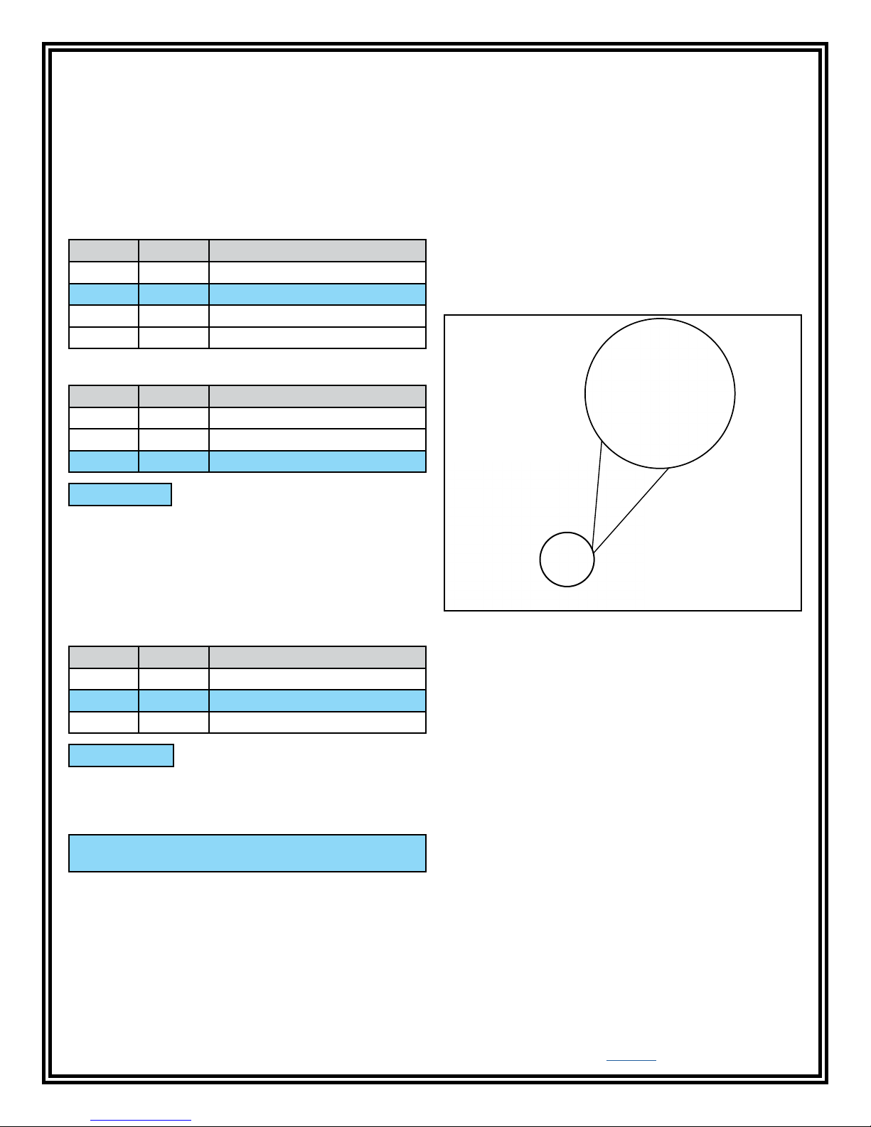
TESTER CONFIGURATION
The resistance limits for footwear and wrist strap tests
are controlled by the DIP switches located on the left
side of the Combo Tester X3. Use the following tables
for the DIP switch settings and their corresponding test
values.
Footwear Resistance
DIP switches 1 and 2 control the HIGH test limit.
INSTALLING THE COMBO TESTER X3
1. Mount the tester at the desired location using the
four mounting holes located in the corners of the
yellow mounting plate.
2. Set the Dual Foot Plate below the tester.
3. Insert one end of the foot plate cord into the stereo
jack located at the bottom of the tester. Insert the
opposite end of the cord into the stereo jack located
at the back of the foot plate.
Switch 1 Switch 2 HIGH Limit Resistance
ON ON 10 Megohms (1 x 10
OFF OFF 35 Megohms (3.5 x 10
ON OFF 100 Megohms (1 x 10
OFF ON 1 Gigohm (1 x 10
7
)
7
)
8
)
9
)
DIP switches 3 and 4 control the LOW test limit.
Switch 3 Switch 4 LOW Limit Resistance
OFF OFF footwear test disabled
ON OFF 100 Kilohms (1 x 10
OFF ON 750 Kilohms (7.5 x 10
5
)
5
)
default setting
NOTE: At 1 Gigohm high limit resistance, a dirty foot
plate could result in a false pass. Be sure to keep the
foot plate clean particularly when using this setting. This
setting is not suitable for relative humidity greater than
50%.
Wrist Strap Resistance
DIP switches 5 and 6 control the HIGH test limit.
Switch 5 Switch 6 HIGH Limit Resistance
OFF OFF wrist strap test disabled
ON ON 10 Megohms (1 x 10
ON OFF 35 Megohms (3.5 x 10
7
)
7
)
default setting
DIP switch 5 must be ON (default setting) for the wrist
strap test to be active. The wrist strap test will be
disabled if DIP switch 5 is set to OFF.
4. Use the guide located on the bottom of the foot
plate to route the cord out of the side. This will
prevent the foot plate cord from being accidentally
tripped and unplugged.
Bottom Side
Figure 3. Routing the foot plate cord through the foot
plate’s guide
5. Insert the ground cord’s banana plug into the
ground jack located at the bottom of the tester.
Connect ground cord’s ring terminal to equipment
ground. This connection will remove any static
charge from the user before the test. NOTE: Failure
to correctly ground the Combo Tester X3 may result
in damage not covered under warranty.
6. Power the Combo Tester X3 using the included
power supply.
The LOW limit for the wrist strap test is set to 750
kilohms and cannot be modified by the user.
DESCO WEST - 3651 Walnut Avenue, Chino, CA 91710 • (909) 627-8178
DESCO EAST - One Colgate Way, Canton, MA 02021-1407 • (781) 821-8370 • Website: Desco.com
TB-3066 Page 3 of 8
© 2017 DESCO INDUSTRIES, INC.
Employee Owned
Page 4
INSTALLING THE COMBO TESTER X3 AND STAND
1. Insert the pedestal to the baseplate with the
mounting bracket sloping toward the operator. Be
sure to align the screw holes located at the base of
the pedestal.
2. Use the two 1/4-20 socket cap screws to secure the
pedestal to the baseplate.
Figure 4. Securing the pedestal to the baseplate using
the 2 socket cap screws
3. Route the ground and foot plate cords through the
pedestal. Feed the cords from the bottom and have
them exit through the top.
Figure 5. Routing the ground and foot plate cords
through the pedestal
4. Align the backplate’s two holes located above and
below the tester to the two holes on the pedestal’s
mounting bracket. Secure the backplate using the
two included 10-32 pan head screws and nuts.
Figure 6. Securing the Combo Tester X3 to the pedestal
5. Insert one end of the foot plate cord into the foot
plate jack located at the bottom of the tester.
Connect the other end of the foot plate cord into the
jack located on the dual foot plate.
6. Insert the ground cord’s banana plug into the
ground jack located at the bottom of the tester.
Connect ground cord’s ring terminal to equipment
ground. This connection will remove any static
charge from the user before the test. NOTE: Failure
to correctly ground the Combo Tester X3 may result
in damage not covered under warranty.
7. Fit the dual foot plate into a position so that it is
flush with the front and top of the baseplate. Secure
the dual foot plate to the baseplate using the four
included #4 pan head screws.
DESCO EAST - One Colgate Way, Canton, MA 02021-1407 • (781) 821-8370 • Website: Desco.com
DESCO WEST - 3651 Walnut Avenue, Chino, CA 91710 • (909) 627-8178
TB-3066 Page 4 of 8
© 2017 DESCO INDUSTRIES, INC.
Employee Owned
Page 5
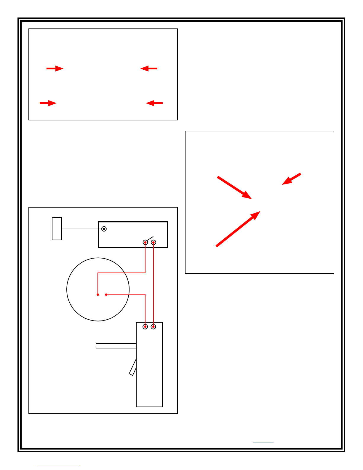
Figure 7. Securing the dual foot plate to the baseplate
8. Power the Combo Tester X3 using the included
power supply.
*NOTE: The Access Control System must have a time
delay feature in order to achieve the configuration
described above. Set the Access Control System’s
relay to remain active for a few seconds when a valid
proximity badge is accepted. The relay will need to
remain active long enough for an operator to perform a
test on the Combo Tester X3. The access control device
will only unlock when it receives an active signal from
both the Access Control System and Combo Tester X3.
Operation
1. A circling light around the test switch indicates when
the Combo Tester X3 is on standby and ready to
perform a test.
WIRING THE COMBO TESTER X3 TO AN ACCESS
CONTROL SYSTEM
The Combo Tester X3 may be connected to an Access
Control System to grant access when both a valid
proximity badge is read and PASS test results are
achieved at the tester. Figure 8 shows an example
when using a turnstile.
DATA
LINES
Proximity
Reader
Combo
Tester X3
(normally open relay
contacts shown above)
Access Control System*
DATA
INPUT
Turnstile
NORMALLY
OPEN RELAY
ACC
INPUT
OUTER
STANDBY
CONTACT
LED
INNER
CONTACT
Figure 9. Steady-State Test Switch features and
components
2. While wearing a wrist strap and/or ESD footwear,
plug the wrist cord into its corresponding jack
located on the face of the Combo Tester X3. Place
one foot on each foot plate.
3. To begin the test, use your finger to bridge the test
switch’s inner and outer contacts. The blue standby
LED will become solid to indicate that the test has
been initiated. Hold your finger down until the test
results are displayed.
If your finger is removed too early, the tester’s LEDs
will blink three times to indicate that the test was not
completed. DO NOT touch any other metal while
performing your test as this will affect your results.
Figure 8. Wiring the Combo Tester X3 to an Access
Control System
DESCO WEST - 3651 Walnut Avenue, Chino, CA 91710 • (909) 627-8178
DESCO EAST - One Colgate Way, Canton, MA 02021-1407 • (781) 821-8370 • Website: Desco.com
TB-3066 Page 5 of 8
© 2017 DESCO INDUSTRIES, INC.
Employee Owned
Page 6
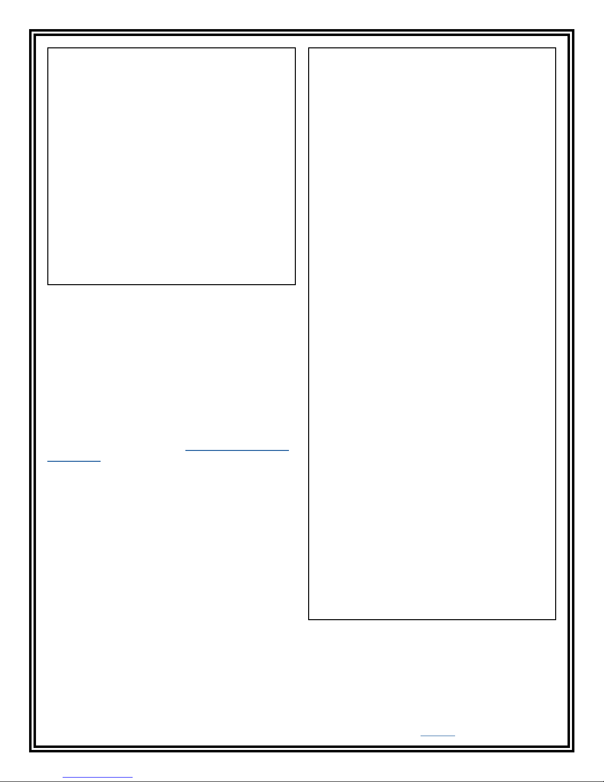
Figure 10. Bridging the test switch’s contacts to initiate
the test
4. A “PASS” test result is indicated by illumination
of the green LEDs. A “FAIL LOW” test result is
indicated by illumination of the red LEDs. A “FAIL
HIGH” test result is indicated by illumination of the
yellow LEDs.
If your ESD test fails, check your wrist strap
and footwear to ensure that they are being worn
correctly and/or need to be replaced.
NOTE: Failures may be caused by dry skin or minimal
sweat layer. For wrist straps, try using an approved
dissipative hand lotion such as Menda Reztore™ ESD
Hand Lotion to your wrist prior to use. Footwear test
results can be improved by taking a short walk to build a
sweat layer for better conductivity.
The Combo Tester X3 may also be used to test smocks
or garments that feature a grounding mechanism for
operators using a coiled cord connection.
DESCO EAST - One Colgate Way, Canton, MA 02021-1407 • (781) 821-8370 • Website: Desco.com
DESCO WEST - 3651 Walnut Avenue, Chino, CA 91710 • (909) 627-8178
TB-3066 Page 6 of 8
Figure 11. Using the 19278 Combo Tester X3
© 2017 DESCO INDUSTRIES, INC.
Employee Owned
Page 7
Calibration
The Combo Tester X3 is calibrated to standards
traceable to NIST. Frequency of recalibration should
be based on the critical nature of those ESD sensitive
items handled and the risk of failure for the ESD
protective equipment and materials. In general, we
recommend that calibration be performed annually.
The accuracy of the Combo Tester X3 is specified as:
±20% for 1 gigohm footwear test limit
±10% for all other test limits
A periodic check using a precision resistance box can
be used to verify proper operation.
The EMIT 50424 Limit Comparator is available for the
convenient calibration of the Combo Tester X3.
The Limit Comparator allows the customer to perform
NIST traceable calibration on the Combo Tester X3. The
Limit Comparator can be used on the shop floor within
a few minutes, virtually eliminating downtime, verifying
that the Combo Tester X3 is operating within tolerances.
See TB-6581 for more information.
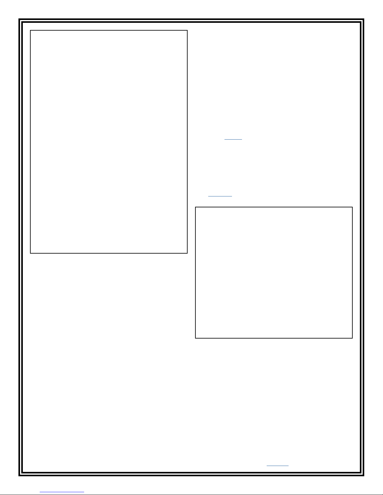
Figure 12. Using the 19279 Combo Tester X3 with Stand
Maintenance
To maintain optimum performance, cleaning should be
performed on a regular basis. Use a minimum of 80%
Isopropyl alcohol to clean the foot plate and test switch.
Other cleaners are susceptible to leaving residue on
these surfaces.
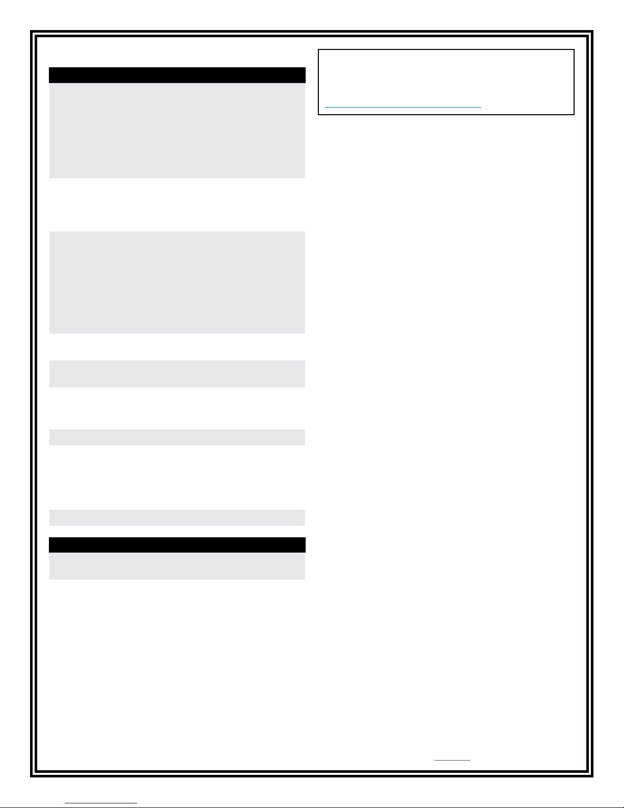
Figure 13. EMIT 50424 Limit Comparator
DESCO EAST - One Colgate Way, Canton, MA 02021-1407 • (781) 821-8370 • Website: Desco.com
DESCO WEST - 3651 Walnut Avenue, Chino, CA 91710 • (909) 627-8178
TB-3066 Page 7 of 8
© 2017 DESCO INDUSTRIES, INC.
Employee Owned
Page 8
Specifications
Combo Tester X3
Input Voltage and
Frequency
(External Adapter)
Operating Temperature 70°F to 85°F (21°C to 30°C)
Environmental
Requirements
Dimensions
(with mounting plate)
Weight
(with mounting plate)
Test Accuracy ±20% for 1 gigohm footwear
Test Switch Voltage 5 VDC @ open circuit
Wrist Strap and
Footwear Test Voltage
Relay Contact Rating 1A @ 30VDC max
AC/DC Power Adapter
Power Input:
100-240VAC, 50/60 Hz
Power Output:
12VDC, 0.5A
Cable Length:
6 ft. (1.83 m)
for 1 gigohm test limit
41°F to 85°F (5°C to 30°C)
for all other test limits
Indoor use only at altitudes
less than 6500 ft. (2 km)
Maximum relative humidity
of 80% up to 85°F (30°C)
decreasing linearly to 50% @
85°F (30°C)
Maximum relative humidity of
50% at 1 gigohm setting
11.35" x 7.75" x 1.47"
(288 mm x 197 mm x 37 mm)
1.2 lbs (0.5 kg)
test limit
±10% for all other test limits
30 VDC @ open circuit
Test current is limited by
resistors and varies on
the test range setting (100
kilohms - 1 gigohm)
Limited Warranty, Warranty Exclusions, Limit
of Liability and RMA Request Instructions
See the Desco Warranty -
Desco.com/Limited-Warranty.aspx
Dual Foot Plate
Dimensions 14.0" x 16.0" x 0.9"
(356 mm x 406 mm x 23 mm)
Weight 7.5 lbs (3.4 kg)
DESCO WEST - 3651 Walnut Avenue, Chino, CA 91710 • (909) 627-8178
DESCO EAST - One Colgate Way, Canton, MA 02021-1407 • (781) 821-8370 • Website: Desco.com
TB-3066 Page 8 of 8
© 2017 DESCO INDUSTRIES, INC.
Employee Owned
 Loading...