

Page 1
TECHNICAL BULLETIN TB-3058
Dual Operator Continuous Monitor
Installation, Operation and Maintenance
The Dual Operator Workstation Continuous Monitor is a
real time instrument that ensures that critical ESD control
components in a sensitive area are effectively grounded. It
independently monitors the operator and the worksurface.
The instant an operators wrist strap or cord fails, the monitor
will issue audible and visual alarms alerting the user of the
problem. In the same manner, the unit also confirms that
a path to ground of less than 10 megohms (1 x 10⁷ ohms)
exists from the ESD protective worksurface(s).
ADVANTAGES OF CONTINUOUS MONITORING
Figure 1. Desco Dual Operator Continuous Monitor with
Satellites
Description
Leading companies use continuous monitors as a cost
effective component in satisfying the section 6.1.3
Compliance Verification Plan requirements of ANSI/ESD
S20.20. The Desco Dual Operator Continuous Monitor with
Satellites continuously monitors the grounding integrity of two
operators, and two ESD worksurfaces’ path to ground. The
monitor will provide instantaneous notification of static control
equipment failures, and eliminates the need of costly and
difficult to supervise wrist strap logging record keeping. This
unit is highly cost effective as it is designed to monitor any
conventional single-wire wrist strap and ground cord system.
Per ESD Handbook ESD TR20.20 section 5.3.2.4.4 Test
Frequency, “Because wrist straps have a finite life, it is
important to develop a test frequency that will guarantee
integrity of the system. Typical test programs recommend
that wrist straps that are used daily should be tested daily.
However, if the products that are being produced are of such
value that knowledge of a continuous, reliable ground is
needed, then continuous monitoring should be considered or
even required.”
The Desco Dual Operator Continuous Monitor is available in
the following models:
Item Power Adapter Input
19246 120VAC
19247 220VAC
OVER PERIODIC TESTING
Many customers are eliminating periodic touch testing of
wrist straps and are utilizing continuous monitoring to better
ensure that their products were manufactured in an ESD
protected environment. Full time continuous monitoring
is superior to periodic or pulsed testing, and can save a
significant amount of money in testing costs and rejected
product. Periodic testing detects wrist strap failures after ESD
susceptible products have been manufactured. The costs
of dealing with the resulting catastrophic failures or latent
defects can be considerable. Dual Operator Workstation
Continuous Monitors eliminate the need for users to test
wrist straps and log the results; by their function, these
monitors satisfy the ISO and ANSI/ESD S20.20 test logging.
ANSI/ESD S20.20 Paragraph 6.2.2.2 Personnel Grounding
Guidance states “A log should be maintained which verifies
that personnel have tested their personal grounding devices.”
Per ESD-S1.1 Paragraph 6.1.3 “Daily (wrist strap system)
testing may be omitted if constant monitoring is used.”
WAVE DISTORTION DETECTION TECHNOLOGY
PROVIDES TRUE 100% CONTINUOUS MONITORING
From the technical alternatives available, Desco designs
and manufactures many of its Continuous Monitor product
offerings using wave distortion technology . Wave distortion
circuitry monitors current/voltage phase shifts and provides
true 100% continuous monitoring. Electrical current will
lead voltage at various points due to the combinations of
resistance and capacitive reactance. By monitoring these
“distortions” or phase shifts, the wave distortion Workstation
Continuous Monitor will reliably determine if the circuit is
complete.
Made in the
United States of America
The Dual Operator Continuous Monitor with Satellites is an
impedance sensing device designed to monitor body types
from a 5th percentile female to a 95th percentile male. This
range covers a 5 foot tall 90 pound person to a 6 foot 5
inch 250 pound person in any production environment.*
The
19246
is powered by a 120 VAC, 60/50 Hz, plug-in
transformer which also provides connection to ground.
No user adjustment required: The Continuous Monitor
is drift-free and designed to be insensitive to the effects of
squeezing or stretching the coil cord. It requires no user
adjustment.
DESCO EAST - One Colgate Way, Canton, MA 02021-1407 • (781) 821-8370 • Website: Desco.com
TB-3058 Page 1 of 5
August 2013
DESCO WEST - 3651 Walnut Avenue, Chino, CA 91710 • (909) 627-8178
*NASA Publication 1024-Anthropomorphic Source Book Volume 1:
“Anthropometry for Designers”
** Per ANSI/ESD S20.20 paragraph 6.0.3. Tailoring “This document,
or portions thereof, may not apply to all applica tions. Tailoring is
accomplished by evaluating the applicability of each requirement
for the specific application. Upon completion of the evaluation,
requirements may be added, modified or deleted. Tailoring
decisions, including rationale, shall be documented in the ESD
Control Program Plan.”
© 2013 DESCO INDUSTRIES, INC.
Employee Owned
Page 2
Wave distortion technology can be referred to as “vector
impedance monitoring”. This description is valid as the
wave distortion technology measures the impedance at the
monitored banana jack and looks for changes in either the
capacitance or resistance of the circuit which includes the
wrist strap and its wearer. It uses filtering and time domain
sampling to filter out false signals caused by voltage offsets,
60 Hz fields and other electro-magnetic and electrostatic
interference.
In normal factory environments, and with persons whose
capacitance with respect to ground is within design limits (5
feet tall 90 pound person to 6 foot 5 inch 250 pound person),
the Dual Operator Workstation Continuous Monitor cannot
be “fooled”. It will provide a reliable alarm only when the
wrist strap or work surface becomes dysfunctional or unsafe
according to accepted industry standards. The Dual Operator
Workstation Continuous Monitor is drift-free and designed to
be insensitive to the effects of squeezing or stretching the
coil cord.
ADVANTAGES OF WAVE DISTORTION AND
SINGLE-WIRE TECHNOLOGY
The Desco Dual Operator Workstation Continuous Monitor
allows the use of any standard, single-wire wrist strap and
coil cord. The monitor/wrist strap/cord system life-cycle costs
are by far lower than alternative systems which require more
expensive & less durable dual-wire cords and special wrist
straps. Dual-wire cords are expensive and are the weak
link of the system. They are the most likely component to
need replacement. Over a five year period this can make
a dual-wire system three times as expensive as a system
utilizing single-wire wrist straps and cords.
Packaging
1 Dual Operator Continuous Monitor (Control Unit)
2 Satellite Remotes (item 19248)
1
Power Adapter, 24VAC
2 Mat Monitor Cords (Black), 6'
2 Mat Ground Cords (Green and Yellow), 6'
2 Satellite Remote Cables, 7'
4 Push and Clinch Snaps
4 Countersink Washers and Screws (#4 x 1/4")
6 Mounting Screws (#8 x 3/4")
1 Certificate of Calibration
Installation
Remove the monitor and satellites from its packaging.
Inspect for any shipping damage. Confirm that the
worksurface is 1 x 10⁷ ohms or less and has a conductive
layer such as Dual Layer Rubber, Dissipative 3-Layer Vinyl,
or Micastat® Dissipative Laminate with conductive buried
layers.
The Control Unit for the Dual Operator Continuous Monitor is
normally installed under the bench top toward the front edge
of a workstation where the LEDs are easily visible. Use the
enclosure’s flanges to mount the monitor.
The dictionary defines constant as uniform and unchanging,
and continuous as uninterrupted. Nonetheless, some
dual-wire resistance monitors utilize a pulsed test current and
do not really provide continuous monitoring. For example,
during each 2.2 second pulse cycle of a leading “constant”
resistive monitor, electrical current is pulsed for only 0.2
seconds followed by an unmonitored interval of 2 seconds.
This leaves the user/wrist strap unmonitored for over 90%
of each cycle. Damaging ESD events can easily occur in
the portion of the time in between the pulses. The off period
of 2 seconds equals 2 billion nanoseconds, and “it takes
only about 25 volts applied for 100 nanoseconds to blow
most memories or microprocessor.”* The dual-wire system
does not meet all industry ESD S6.1 specifications, as the
cords do not meet the EOS/ESD Association guidelines
for the 1 to 5 pound “breakaway force” requirement for
ensuring a reliable path-to-ground and preventing accidental
disconnects.
By using the reliable wave distortion technology to determine
if the circuit is complete, there are no false alarms. There
is no need to adjust or tune the monitor to a specific user
or installation. The miniscule amount of electrical current
(less than 1 volt coil cord signal) required to generate the
waveform has never caused reported skin irritation and is
extremely safe for use in voltage sensitive applications such
as disk drive manufacturing.
screws
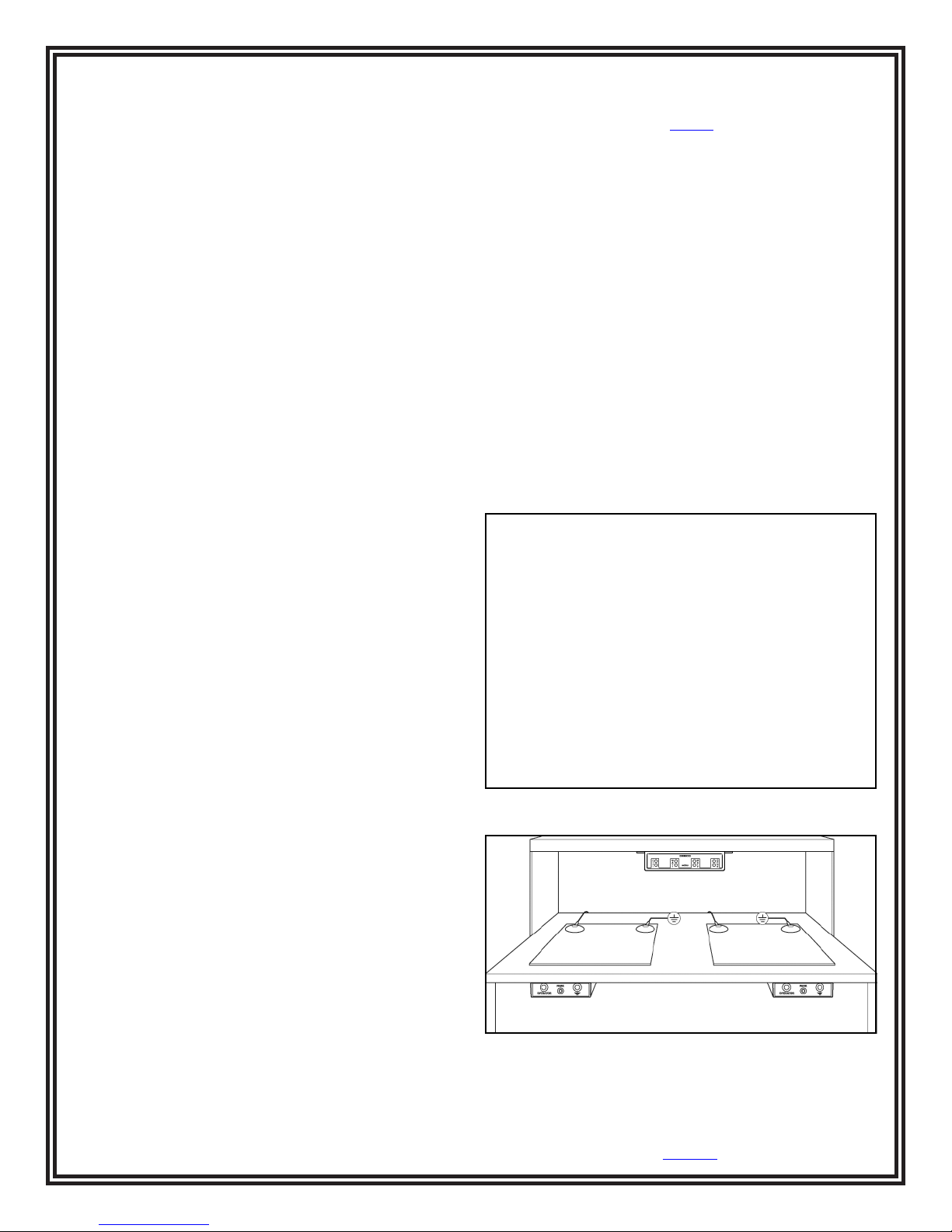
Figure 2. Mounting the Control Unit
Figure 3. Typical setup of the Dual Operator Continuous
Monitor and Satellites
*1981 article by Donald E. Frank - Electrical Overstress Electronic
Discharge Symposium Proceedings
DESCO WEST - 3651 Walnut Avenue, Chino, CA 91710 • (909) 627-8178
DESCO EAST - One Colgate Way, Canton, MA 02021-1407 • (781) 821-8370 • Website: Desco.com
TB-3058 Page 2 of 5
© 2013 DESCO INDUSTRIES, INC.
Employee Owned
Page 3
SATELLITE REMOTES
The Satellite Remotes can
be installed up to 7 feet
away from the monitor
control unit. Two operators
plus two worksurfaces
can be monitored at separate adjacent workstations. The
worksurface mat circuit may be bypassed by a switch located
at the rear of the satellite. Also shown on each satellite
remote is an unmonitored ground connection jack where a
supervisor, guest, or equipment can be grounded.
2. Connect the Satellite Remotes to the Control Unit using
the included cables.
Power Adapter
Replacement Satellites are offered as Desco item
NOTE: The
with the
19248
19246
Replacement Satellite is only compatible
and
19247
Dual Operator Continuous
19248
.
Monitors.
The following procedure will outline how to correctly install
the Dual Operator Continuous Monitor and its satellites to
properly monitor an ESD protected workstation.
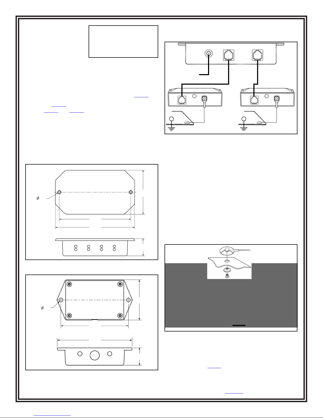
1. Follow the dimensions listed in figures 4 and 5 to properly
mount the Dual Operator Monitor’s Control Unit and
Satellite Remotes.
2X .21"
4.63"
5.13"
2.85"
1.11"
Figure 4. Mounting hole locations of the Control Unit
Workstation #2 Workstation #1
Figure 6. Typical setup of the Dual Operator Continuous
Monitor and Satellites
3. Mat monitoring may be bypassed by using the switch
located inside the hole located at the rear of the satellite
remote.
4. Install Screws and Washers or Push and Clinch snaps
12 to 72 inches apart from each other on the worksurface
mat. Make sure that they pierce and clinch the bottom
side of the mat.
5. Ground the worksurfaces by using the included mat
ground cords. Snap one end to the worksurface mat and
connect the other end to common point ground.
6. Connect the mat ground cord to the remaining worksurface
snap. Connect the other end of the cord to the back of the
satellite remote.
Screw allows ground
cord to be bolted to
mat and prevent it
from disconnecting
or
2X .19"
3.50"
3.87"
Figure 5. Mounting hole locations of the Satellite
Remote
DESCO WEST - 3651 Walnut Avenue, Chino, CA 91710 • (909) 627-8178
DESCO EAST - One Colgate Way, Canton, MA 02021-1407 • (781) 821-8370 • Website: Desco.com
TB-3058 Page 3 of 5
2.09"
.90"
Mat Ground
Cord
Worksurface Mat
Mat Monitor
Cord
To Satellite
Figure 7. Installing the Mat Ground and Mat Monitor
Cords
7. A convenient 3-wire 120 VAC outlet should be located and
tested for proper wiring and grounding. We recommend
using the Desco 98130 AC Outlet Analyzer to perform
these tests.
© 2013 DESCO INDUSTRIES, INC.
Employee Owned
Page 4

8. Plug the power adapter into the outlet and connect its
plug into the power jack located at the back of the Control
Unit. The green worksurface LEDs should illuminate. If
the red worksurface LED(s) illuminate and alarm, inspect
the snap fastener and ground cords for proper connection.
The operator LEDs will illuminate red when an operator is
not connected. The Dual Operator Continuous Monitor is
now ready for use.
Installation on Micastat® Laminate
Materials Needed:
2 Flush Mount Ground Laminate Inserts
1 Installation Tool for Flush Mount Insert
1. Install the Flush Mount Inserts first. It is recommended to
install one in the right back corner and the other in the left
back corner of the Micastat® laminated bench top.
2. Once both inserts are installed, cut the ground cord
supplied with the monitor into two pieces; make sure that
the tinned end is long enough to connect from the
worksurface terminal on the Satellite Remote to one of the
flush mount terminals located under the bench.
3. The remaining wire can then be used to connect the other
flush mount terminal to ground using the supplied ring
terminal. The shrouded molded end can then be cut off.
When complete, one flush mount terminal will connect the
Micastat® laminate to ground while the other will connect
it to a satellite remote. The satellite remote then monitors
the ground connection between the two inserts, and since
Micastat® is the only ESD laminate made with a physical
uniform ground layer, it will monitor the entire Micastat®
surface ground. The wires will stay under the bench,
maximizing the usable space on the bench top.
When leaving the area, the operator may take the wrist cord
along or unsnap the cord from wristband and attach it to
the parking snap located on the satellite remote. This will
de-activate the alarm and allow the operator to leave the
workstation. If the cord is plugged into the OPERATOR jack,
the monitor will alarm continuously until the cord is either
parked or unplugged.
WORKSURFACE CHANNEL
The Dual Operator Continuous Monitor’s worksurface
monitoring circuitry is sufficiently sensitive to detect
extremely low current, allowing it to be used with mats having
a resistance of up to 1 x 10⁷ ohms (10 megohms). If the user
desires not to monitor the worksurface, the circuit can be
bypassed with the switch located at the rear of the satellite.
When the monitor is connected to a static dissipative
worksurface, the amount of current that flows is a function of
the total resistance between the monitor and the worksurface
to ground. When the resistance of the worksurface is below a
present threshold, the monitor will indicate good. Conversely,
if the resistance level is high when compared to the monitor’s
reference, the unit will alarm. This is an integrating resistance
measuring circuit. Therefore, it is relatively insensitive to
externally induced electromagnetic fields. The resistance
threshold is factory set to 10 megohms (1 x 10⁷ ohms).
Custom worksurface range is available upon request.
Contact customer service for more details.
Note: Per ESD S6.1, Grounding paragraph 4.1.1 “Every
element to be grounded at an ESD protected station shall
be connected to the same common point ground.” The
ESD control plan should include a tailoring** statement
that continuous monitors are used and that consistent with
manufacturer’s design grounding is via AC adapter cord to
equipment ground.
Operation
When the satellite remote unit is installed and connected
to a grounded ESD protective worksurface, the monitor’s
green worksurfaces LED’s and red operator LED’s should
be illuminated. The monitor takes 6 seconds to activate its
audible alarm circuitry when first powered.
To use the monitor:
1. Plug a wrist strap cord, into the jack labeled OPERATOR
on the satellite remotes. This automatically activates the
selected operator channel. The red operator LED should
illuminate, and the buzzer should sound.
2. Remove the charges from your body by making contact
with a properly grounded ESD worksurface. Snap the
cord to the wristband, which should fit snugly on your
wrist. This should silence the alarm and cause the LEDs
to switch from red to green. If this does not happen,
check the wrist cord for continuity or damage. Examine
your wristband and ensure that it has a secure fit. If you
have dry skin, use ESD hand lotion such as Menda
35666 Reztore™ ESD Hand Lotion.
DESCO WEST - 3651 Walnut Avenue, Chino, CA 91710 • (909) 627-8178
DESCO EAST - One Colgate Way, Canton, MA 02021-1407 • (781) 821-8370 • Website: Desco.com
Maintenance and Calibration
The Dual Operator Workstation Continuous Monitor is solid
state and designed to be maintenance free. It is calibrated
to NIST traceable standards. There are no user adjustments
that can be made. Because of the impedance sensing
nature of the test circuit, special equipment is required
for calibration. We recommend using the Desco 98220
Continuous Monitor Calibration Unit whenever calibration
is performed annually or any of the satellite remotes are
replaced. The Calibration Unit is a most important product
which allows the customer to perform NIST traceable
calibration on continuous monitors and can be used to
perform compliance verification required by ANSI/ESD
S20.20 Section 6.2.2.2. The Desco 98220 is designed to be
used on the shop floor at the workstation, virtually eliminating
downtime, verifying that the continuous monitor is operating
within tolerances.
TB-3058 Page 4 of 5
© 2013 DESCO INDUSTRIES, INC.
Employee Owned
Page 5

Specifications
Test range of monitored circuit 500K - 10M ohms†
Supervisor Jack
Resistance to Ground 47k ohms typical
Worksurface Limit* Set to 10 Megohms
(1 x 10⁷ ohms)
Operating Voltage 120 VAC, 50-60 Hz (
220 VAC, 50-60 Hz (
Wrist strap open circuit voltage 1.2 volts peak to peak @
1-2 MicroAmps
Mat test open circuit voltage 5 to 7.5 volts
Response time to alarm < 50 mS
Operating Temperature 0 - 40°C
Long Term Drift <0.5% per Decade
(1st Decade is 1 hr)
NOTE: Worksurface must have a conductive layer such as
Dual Layer Rubber or Dissipative 3-Layer Vinyl or Micastat®
Dissipative Laminate with conductive buried layers.
Desco Continuous Monitors are not recommended for use
with homogeneous matting.
† This cannot be verified with standard DC test equipment.
The continuous monitor is an impedance sensing device and
the limits are determined by the magnitude and angle of the
impedance.
19246
19247
)
)
Limited Warranty
Desco expressly warrants that for a period of one (1) year from the date
of purchase Desco Continuous Monitors will be free of defects in material
(parts) and workmanship (labor). Within the warranty period, a credit
for purchase of replacement Desco Continuous Monitors, or, at Desco’s
option, the Continuous Monitor will be repaired or replaced free of charge.
If product credit is issued, the amount will be calculated by multiplying
the unused portion of the expected one year life times the original unit
purchase price. Call our Customer Service Department at 909-627-8178
(Chino, CA) or 781-821-8370 (Canton, MA) for a Return Material
Authorization (RMA) and proper shipping instructions and address. Please
include a copy of your original packing slip, invoice, or other proof of date
of purchase. Any unit under warranty should be shipped prepaid to the
Desco factory. Warranty replacements will take approximately two weeks.
If your unit is out of warranty, call our Customer Service Department at
909-627-8178 (Chino, CA) or 781-821-8370 (Canton, MA) for a Return
Material Authorization (RMA) and proper shipping instructions and
address. Desco will quote repair charges necessary to bring your unit up
to factory standards.
Warranty Exclusions
THE FOREGOING EXPRESS WARRANTY IS MADE IN LIEU OF
ALL OTHER PRODUCT WARRANTIES, EXPRESSED AND IMPLIED,
INCLUDING MERCHANTABILITY AND FITNESS FOR A PARTICULAR
PURPOSE WHICH ARE SPECIFICALLY DISCLAIMED. The express
warranty will not apply to defects or damage due to accidents, neglect,
misuse, alterations, operator error, or failure to properly maintain, clean or
repair products.
Limit of Liability
In no event will Desco or any seller be responsible or liable for any injury,
loss or damage, direct or consequential, arising out of the use of or
the inability to use the product. Before using, users shall determine the
suitability of the product for their intended use, and users assume all risk
and liability whatsoever in connection therewith.
*Contact factory for special limits.
DESCO EAST - One Colgate Way, Canton, MA 02021-1407 • (781) 821-8370 • Website: Desco.com
DESCO WEST - 3651 Walnut Avenue, Chino, CA 91710 • (909) 627-8178
TB-3058 Page 5 of 5
© 2013 DESCO INDUSTRIES, INC.
Employee Owned
 Loading...