

Desa VDDVF36STN-STP, VDDVF36PN-PP User Manual

DIRECT-VENT GAS
FIREPLACE
OWNER’S OPERATION AND
®
INSTALLATION MANUAL
For more information, visit www.desatech.com
For more information, visit www.desatech.com
(Peninsula Shown)
VDDVF36PN/PP (PENINSULA) AND VDDVF36STN/STP (SEE-THRU)
WARNING: If the information in these instructions
is not followed exactly, a fire or explosion may
result causing property damage, personal injury, or
loss of life.
— Do not store or use gasoline or other flammable
vapors and liquids in the vicinity of this or any
other appliance.
— WHAT TO DO IF YOU SMELL GAS :
• Do not try to light any appliance.
• Do not touch any electrical switch;
• Do not use any phone in your building.
• Immediately call your gas supplier from a
neighbor’s phone. Follow the gas supplier’s
instructions.
• If you cannot reach your gas supplier, call the
fire department.
— Installation and service must be performed by a quali-
fied installer, service agency, or the gas supplier.
SAVE THIS BOOK
This book is valuable. In addition to instructing
you on how to install and maintain your appliance, it also contains information that will
enable you to obtain replacement parts or
optional accessory items when needed. Keep
it with your other important papers.
WARNING: Improper installation,
adjustment, alteration, service, or
maintenance to this appliance can
cause injury or property damage.
Refer to this manual. For assistance
or additional information consult a
qualified installer, service agency,
or the gas supplier.
WARNING: This Direct-Vent Gas
Fireplace series is intended for use
with Natural or Propane/LP gas only.
Do not attempt to burn any solid
fuels in these appliances.
CHECK LOCAL CODES PRIOR TO INSTALLATION
This appliance may be installed in an aftermarket* permanently located, manufactured
(mobile) home, where not prohibited by state or local codes.
This appliance is only for use with the type of gas indicated on the rating plate. This appliance
is not convertible for use with other gases, unless a certified kit is used.
* Aftermarket: Completion of sale, not for purpose of resale, from the manufacturer.
Save this manual for future reference.
Save this manual for future reference.
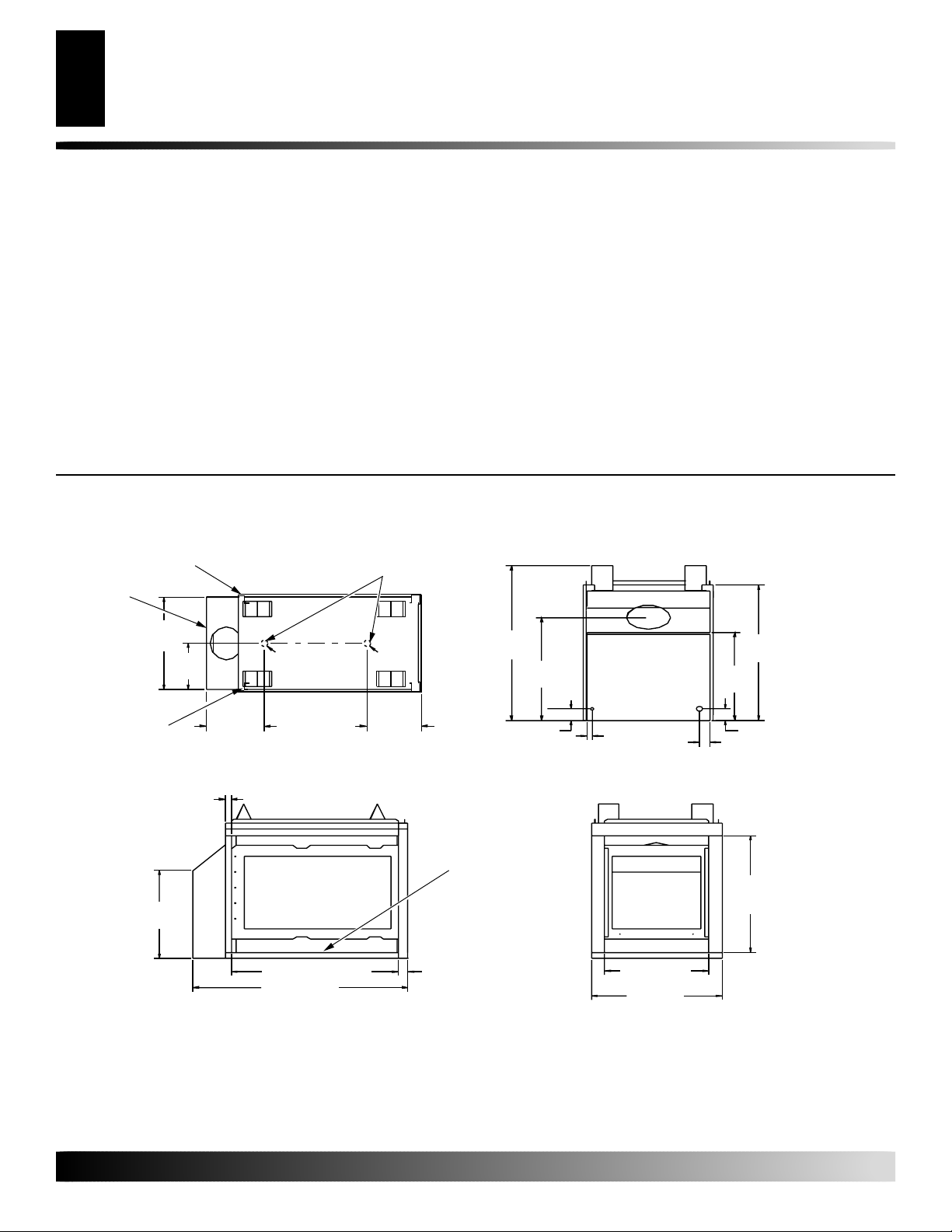
TABLE OF CONTENTS
2
PRODUCT DIMENSIONS
TABLE OF CONTENTS
PRODUCT DIMENSIONS........................................................... 2
GLOSSARY OF TERMS............................................................. 3
INTRODUCTION......................................................................... 3
SELECTING LOCATION............................................................. 4
PRE-INSTALLATION PREPARATION ........................................ 5
GENERAL VENTING .................................................................. 7
VENTING INSTALLATION .......................................................... 9
INSTALLATION ......................................................................... 16
PILOT ASSEMBL Y ADJUSTMENT........................................... 20
BURNER FLAME ADJUSTMENT............................................. 20
OPERATING GUIDELINES AND MAINTENANCE
INSTRUCTIONS ....................................................................... 21
PRODUCT DIMENSIONS
Back of
Surround
Right Side
Surround
Left Side
Surround
(Back)
23 5/8"
(60cm)
11
(30cm)
(Left Side)
15
/16"
1.5"ø
(4cm)
(Right Side)
1
10
/2"
(27cm)
Alternate Gas
Supply Inlets
(Front)
1.5"ø
(4cm)
10 1/2"
(27cm)
CLEANING AND MAINTENANCE ............................................ 21
OPERATING FIREPLACE ........................................................ 22
TROUBLESHOOTING .............................................................. 24
WIRING DIAGRAM ................................................................... 28
ACCESSORIES ........................................................................ 28
SERVICE HINTS....................................................................... 28
TECHNICAL SERVICE ............................................................. 28
REPLACEMENT PARTS .......................................................... 29
REPLACEMENT PARTS LIST.................................................. 29
OWNER’S REGISTRATION FORM.......................................... 31
WARRANTY INFORMATION...................................... Back Cover
BA CK VIEWTOP VIEW
39 3/4"
(101cm)
3" (8cm)
3
/8"
26
(67cm)
1" (3cm)
(88cm)
5
22
/8"
(57cm)
3" (8cm)
2" (5cm)
34
3
/4"
1 1/4" (3cm)
RIGHT SIDE
5
22
/8"
(57cm)
32" (81cm) (Opening) 1
1
41
/8" (104cm)
Figure 1 - VDDVF36PN/PP (Peninsula) Dimensions
For more information, visit www.desatech.com
For more information, visit www.desatech.com
Rating Plate
Location
7
/8" (5cm)
FRONT VIEW
7
19
/8" (50cm)
(Opening)
25" (64cm)
30"
(76cm)
(Opening)
106918-01B
FIREBOX DIMENSIONS
Continued
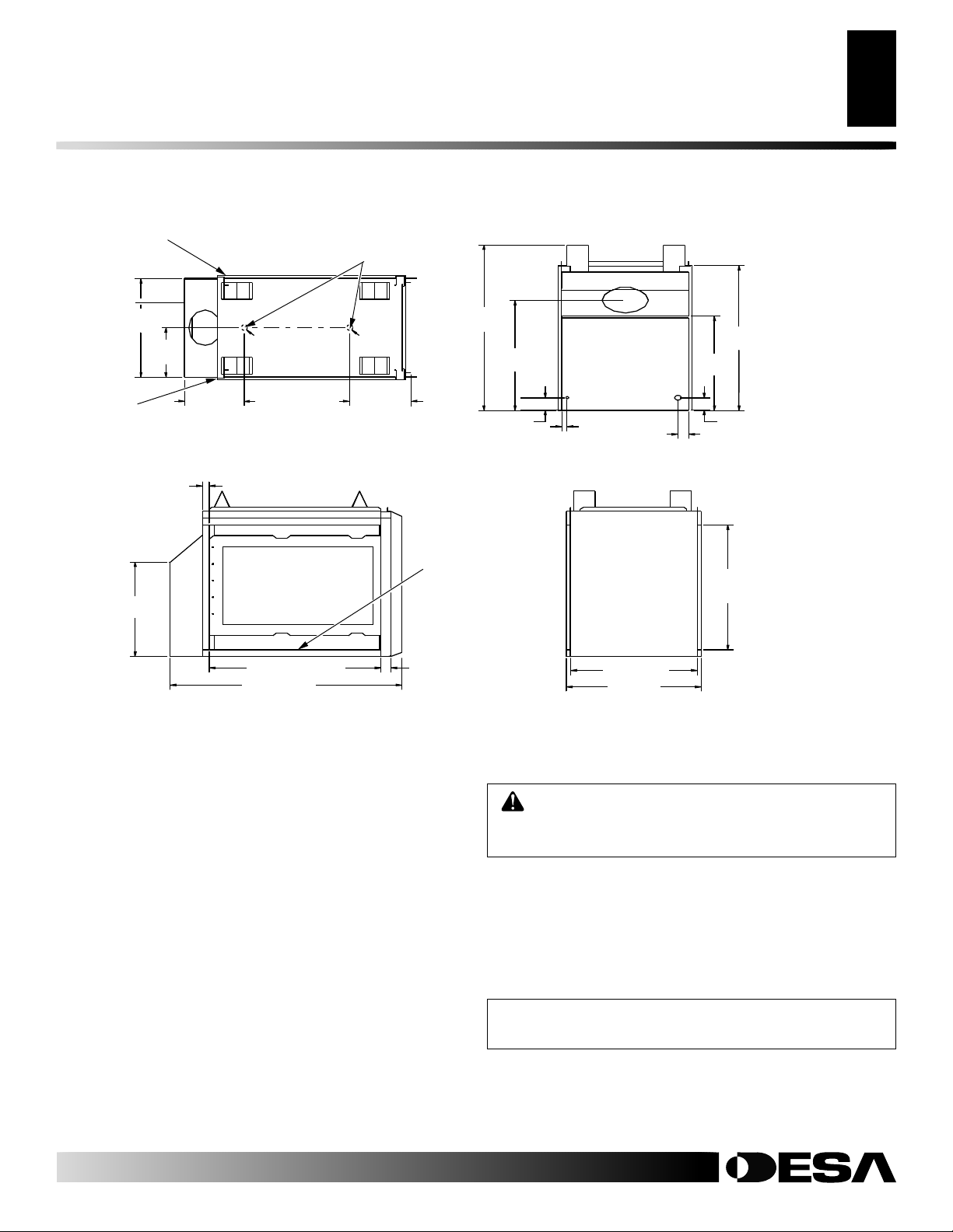
PRODUCT DIMENSIONS
GLOSSARY OF TERMS
INTRODUCTION
3
3
Back of
Surround
(Back)
Right Side
Surround
Left Side
Surround
23 5/8"
(60cm)
11
1
1
/4" (3cm)
22 5/8"
(57cm)
15
(30cm)
/16"
10 1/2"
(27cm)
TOP VIEW
RIGHT SIDE
(Left Side)
1.5"ø
(4cm)
(Right Side)
32" (81cm) (Opening)
1
43
/8" (110cm)
Alternate Gas
Supply Inlets
11 1/8"
(28cm)
(Front)
7
/8" (5cm)
1
1.5"ø
(4cm)
39 3/4"
(101cm)
Rating Plate
Location
3
26
/8"
(67cm)
3" (8cm)
BA CK VIEW
1" (3cm)
FRONT VIEW
5
/8" (60cm)
23
25" (64cm)
34
(88cm)
5
/8"
22
(57cm)
3" (8cm)
2" (5cm)
30"
(76cm)
(Opening)
3
/4"
Figure 2 - VDDVF36STN/STP (See-thru) Dimensions
GLOSSARY OF TERMS
Chase - A boxlike enclosure to protect venting from the elements
when the venting run is on the outside of a structure.
Mastic - A pliable sealant for use around the vent terminal.
Snorkel Termination - A box that raises the horizontal termination
above ground level clearances.
Vent Terminal - Mounted on an outside wall or roof to separate the
inlet and outlet of the vent system and protect it from weather.
Vinyl Siding Standoff - A metal box that separates the vent cap from
vinyl siding.
Wall Thimble/Firestop - A metal plate used to secure the vent pipe
when it passes through a wall or ceiling.
INTRODUCTION
WARNING: This product contains and/or generates
chemicals known to the State of California to cause
cancer or birth defects, or other reproductive harm.
Models VDDVF36PN/PP series are three-sided direct-vent gas
fireplace with a sealed combustion chamber. Models
VDDVF36STN/STP series are two-sided direct-vent gas fireplace
with a sealed combustion chamber. All models use a millivolt gas
control and a millivolt ignition system. All models have a manual
HI/LO valve to control the flame height. A fan kit is available for
these models as an option (see Accessories on page 28).
NOTICE: Check local building codes for area requirements before installing this appliance.
• Models VDDVF36PN and VDDVF36STN use NATURAL GAS
ONLY.
• Models VDDVF36PP and VDDVF36STP use PROPANE/LP
GAS ONLY.
106918-01B
For more information, visit www.desatech.com
For more information, visit www.desatech.com

INTRODUCTION
4
Before You Begin
SELECTING LOCATION
INTRODUCTION
Continued
If you have any doubts as to which gas your particular appliance is
approved and tested for, please check the CSA rating plate located
at the interior of the appliance opening or consult your local
distributor (see Figure 1, page 2 and Figure 2, page 3).
BEFORE YOU BEGIN
Before beginning the installation of your appliance, read these
instructions through completely.
This DESA appliance and its approved components are safe when
installed according to this installation manual and operated as
recommended by DESA. Unless you use DESA approved components tested for this appliance, YOU MAY CAUSE A SAFETY
HAZARD!
The DESA warranty will be voided by, and DESA disclaims any
responsibility for the following actions:
A) Modification of the appliance or any of the components manu-
factured by DESA unless otherwise permitted in writing by
DESA.
B) The use of any components part not approved by DESA in
combination with this DESA appliance.
C) Installation and/or operation in a manner other than instructed
in this manual.
D) The burning of anything other than the type of gas approved
for use in this gas appliance.
This appliance, when installed, must be electrically grounded in
accordance with local codes, or in the absence of local codes, with
the National Electrical Code, ANSI/NFPA 70 or the Canadian
Electrical Code, CSA C22.1.
The installation must conform with local codes or, in the absence of
local codes, with the National Fuel Gas Code, ANSI Z223.1 or the
Canadian Installation Code, CAN/CGA B149.
This appliance complies with ANSI Z21.50-1998/CSA 2.22-M48
as a VENTED GAS FIREPLACE. It is listed and tested by International Approval Services.
SELECTING LOCATION
To determine the safest and most efficient location for your appliance, consider the following guidelines:
1. The location must allow for proper clearances (see Clearances,
page 5).
2. Consider a location where heat output would not be affected
by drafts, air conditioning ducts, windows, or doors.
3. A location that avoids the cutting of joists or roof rafters makes
installation easier.
In selecting a location, the following precautions must be observed:
1. A projection may be ideal for a new addition on an existing fin-
ished wall. See Horizontal Termination Configuration, page 12,
or Vertical Termination Configuration, pages 14 and 15.
2. Do not locate appliance close to where gasoline or other flam-
mable liquids may be stored. The appliance must be kept clear
and free from combustible materials.
3. Do not connect this appliance to a chimney system used for
solid fuel burning fireplace.
4. Due to high temperatures, do not locate this appliance in high
traffic areas or near furniture and draperies.
5. This fireplace may be installed in bedrooms or bathrooms in
accordance with local codes.
6. Never obstruct the openings of the appliance or flow of venti-
lation air. Keep the control compartments accessible.
7. Do not use this appliance if any part has been under water. Im-
mediately contact a local service technician to examine the appliance and to replace any part(s) of the control ignition system
and other related components that have submerged under water .
NOTICE: This appliance is intended to be used only
for supplemental heat.
WARNING: Installation and repair should be done
by a qualified installer/service person. The appliance
should be inspected before use, and at least annually
thereafter by a qualified service person. More frequent cleaning may be required due to excessive lint
from carpeting, bedding, pet hair, etc. It is imperative
that the control compartments, burners, and circulating air systems be kept clean.
For more information, visit www.desatech.com
For more information, visit www.desatech.com
Figure 3 - Possible Installation of Peninsula Fireplace
106918-01B

PRE-INSTALLATION
PREPARATION
PRE-INSTALLATION PREPARATION
Clearances
Mantel Clearances
Framing
5
5
CLEARANCES
Minimum clearances to combustibles are:
• Back and Sides of Surround: .................................. 0" min.
• Vent Surfaces: ............................................1" (2.5cm) min.
• Ceiling to Opening: ..................................36" (91cm) min.
• Floor: ...................................................................... 0" min.
• Wall to Front of Glass: .............................36" (91cm) min.
• Perpendicular Wall to Opening of Unit: .......2" (5cm) min.
• Top Spacer:............................................................. 0" min.
CAUTION: Do not block required air spaces with
insulation or any other material. Do not obstruct the
effective opening of the appliance with any type of
facing material.
CEILING
36"
(91cm)
Min.
WALL
MANTEL CLEARANCES
Woodwork, such as wood trims, mantels, and other combustible
materials projecting no more than 1
placed within 7 inches (17.8cm) from the opening of the unit.
Combustible material above and projecting more than 1 1/2 inches
(3.8cm) from the appliance’s face must not be placed less than 15
inches (38.1cm) from the louver opening (see Figure 6).
Combustible
Material May
Be Used
21"
(53.3cm)
Min.
15"
(38.1cm)
Min.
Top of Louver
Opening
Figure 6 - Mantel Clearances for Peninsula and See-thru
Fireplaces (Peninsula Shown)
12"
(30.5cm)
Min.
4"
(10.2cm)
Min.
7" (17.8cm)
Min.
1
/2 inches (3.8cm) shall not be
Drywall (Gypsum
Board, Sheetrock, Etc.)
Safe Zone for Projection
of Combustible Material
2 x 4
Spacer
1
1
/2" (3.8cm)
Min.
UNIT
36"
(91cm)
Min.
0" Floor
Figure 4 - Minimum Clearances (Peninsula Shown)
Left Side
Surround
TOP VIEW
0"
(0" Min.)
Combustible
Material
Minimum 1"(2.5cm)
Clearance from Side
(Only for See-thru)
Right Side
Surround
(0" Min.)
Perpendicular
Wall 2" (5cm)
2" (5cm)
Wall In Front Of Glass
36" (91cm) Min.
36"
(91cm)
Min. From Opening
Figure 5 - Minimum Clearances (See-thru Shown)
Drywall
2 x 4 Stud
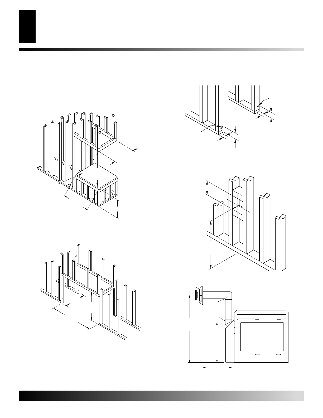
FRAMING
Once the final location has been determined, observing height
clearances for vent termination, you may construct framing using
dimensions shown in Figure 7 and Figures 8 and 9, page 6,
depending on your installation.
If the appliance is to be installed directly on carpeting, tile (other
than ceramic), or any combustible material other than wood flooring, the appliance must be installed on a metal or wood panel
extending the full width and depth of the appliance. There are three
holes on each side of the bottom of the unit where screws can be used
to secure the unit to the floor.
"
8
/
5
)
23
(60cm
40
1
(102.9cm
/
2
"
Figure 7 - Rough Opening for Installing Peninsula Fireplace
39 3/4"
(101cm)
)
Min.
106918-01B
For more information, visit www.desatech.com
For more information, visit www.desatech.com
PRE-INSTALLATION PREPARATION
6
Framing (Cont.)
PRE-INSTALLATION
PREPARATION
Continued
The gas supply line may be connected through the side framing or
alternately through the lower sub-flooring or a platform base if
provided (see Figures 10 and 11). Depending on the installation,
refer to the appropriate illustration.
"
8
/
5
)
23
(60cm
39 3/4"
(101cm)
Min.
Platform Must Be
Solid, Flat, and
Fully Supported
40
1
(102.9cm
/
2
"
)
*
1" (2.5cm)
Dia. Hole
1"
(2.5cm)
3"
2" (5.1cm)
Dia. Hole
(7.6cm)
2"
(5.1cm)
3" (7.6cm)
Figure 10 - Hole Locations For Gas Line and Electric Wires for
Peninsula and See-thru Fireplaces
10"
(25.4cm)
Square Min.
Figure 8 - Rough Opening for Installing Peninsula Fireplace on
Platform
* As required by design as long as ceiling clearance is maintained.
"
8
/
5
)
23
(60cm
39 3/4"
(101cm)
Min.
43
1
(109.8cm
/4"
)
Figure 9 - Rough Opening for Installing See-thru Fireplace
Height
Depends On
Installation
Figure 11 - Rough Opening for Installing Exterior Vent Terminal
Refer to Pages 10 through 16
for Horizontal and Vertical
Installation Details
Vertical Height
Depends on
Installation
o
90
Elbow
o
45
Elbow
3
26
/8"
(67cm)
Horizontal
Length Depends
on Installation
Figure 12 - Vent Opening Height
For more information, visit www.desatech.com
For more information, visit www.desatech.com
106918-01B

GENERAL VENTING
These models are approved for use with Simpson Dura-Vent 6 5/8"
direct-vent pipe components and terminations as well as both flex
and rigid Vanguard vent components.
Your fireplace is approved to be vented either through the side wall,
or vertically using the following guidelines:
• Only use Vanguard or Simpson Dura-Vent GS venting components or kits specifically approved for this fireplace.
• Minimum clearance between vent pipes and combustible materials is 1" (25 mm), except where stated otherwise.
• Combustible material may be flush with the top front of fireplace with a maximum thickness of 3/4".
• Do not recess venting terminals into a wall or siding.
• Install horizontal venting with a 1/4" rise for every 12" of run
toward the termination.
• You may paint the vent terminal with 450°F (232°C) heat-resistant paint to coordinate with the exterior finish.
• There must not be any obstruction such as bushes, garden sheds,
fences, decks, or utility buildings within 24" from the front of
the termination cap.
• Do not locate termination cap where excessive snow or ice build
up may occur. Be sure to clear vent termination area after snow
falls to prevent accidental blockage of venting system. When
using snow blowers, do not direct snow towards vent termination area.
Location Of Vent Termination
GENERAL VENTING
7
7
LOCATION OF VENT TERMINATION
When locating vent termination, it is important to observe the
minimum clearances shown in Figure 13, page 8. You will avoid
extra framing by positioning your fireplace against an already
existing framing member. The sides of the fireplace may be positioned directly against combustible walls.
*Check with local codes or with the current CAN/CGA B149[.1 or
.2] Installation Codes for Canada or the USA installations follow
the current National Fuel Gas Code, ANSI Z223.1/NFPA 54.
106918-01B
For more information, visit www.desatech.com
For more information, visit www.desatech.com
GENERAL VENTING
8
Location Of Vent Termination (Cont.)
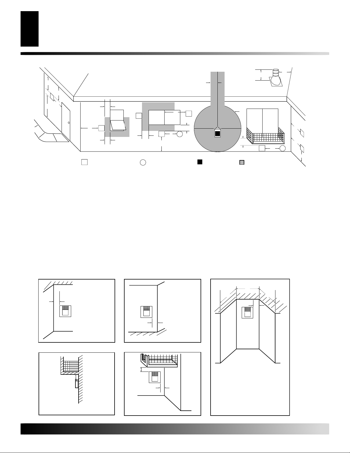
GENERAL VENTING
D
E
V
B
L
F
V
TERMINATION CAP
V
A = clearance above grade, veranda, porch, deck, or balcony
[*12 inches (30.5cm) minimum]
B = clearance to window or door that may be opened
[12 inches (30.5cm) minimum]
C = clearance to permanently closed window [minimum 12 inches
(30.5cm) recommended to prevent condensation on window]
D = vertical clearance to ventilated soffit located above the terminal
within a horizontal distance of 24 inches (61cm) from the
center-line of the terminal [18 inches (45.7cm) minimum]
E = clearance to unventilated soffit [12 inches (30.5cm) minimum]
F = clearance to outside corner (see below)
G = clearance to inside corner (see below)
H = *not to be installed above a meter/regulator assembly within
36 inches (91.4cm) horizontally from the center-line of the regulator
vent shall not terminate directly above a side-walk or paved driveway which is located between two
single family dwellings and serves both dwellings*
only permitted if veranda, porch, deck or balconey is fully open on a minimum of 2 sides beneath the floor*
* as specified in CAN/SGA B149 (.1 or .2) Installation Codes (1991) for Canada or for U.S.A. installation follow
the current
Note: Local codes or regulations may require different clearances
National Fuel Gas Code, ANSI Z223.1
C
Fixed
Closed
Openable
B
Continued
V
Openable
B
AIR SUPPLY INLET
X
B
Fixed
Closed
J
V
A
X
I = clearance to service regulator vent outlet [*72 inches (182.9cm)
minimum]
J = clearance to non-mechanical air supply inlet to building or the
combustion air inlet to any other fireplace [*12 inches (30.5cm)
minimum]
K = clearance to a mechanical air supply inlet [*72 inches (182.9cm)
minimum]
L = clearance above paved side-walk or a paved driveway located on
public property [*84 inches (213.4cm) minimum]
M = clearance under veranda, porch, deck [*12 inches (30.5cm) minimum ]
N = clearance above a roof shall extend a minimum of 24 inches (61cm)
above the highest point when it passes through the roof surface and
any other obstruction within a horizontal distance of 18 inches (45.7cm)
Termination Clearances for Buildings with Combustible and Noncombustible Exteriors
Inside Corner
Outside Corner Recessed Location
N
H
V
B
G
G
GAS METER RESTRICTED AREA
I
M
V
(TERMINATION PROHIBITED)
N
G
V
G
X
K
V
A
A
Balcony with No Side Wall
G = Combustible 24" (61cm)
Noncombustible 18" (45.7cm)
V
G
V
A = 6" (15.2cm)
V
Balcony with Perpendicular Side Wall
H
Combustible &
Noncombustible
H = 24" (61cm)
J = 20" (50.8cm)
Figure 13 - Minimum Clearances for Vent Terminations
For more information, visit www.desatech.com
For more information, visit www.desatech.com
B
V
J
B = 6" (15.2cm)
D
C
V
C = Maximum depth of 48" (121.9cm) for
recessed location
D = Minimum width for back wall of
recessed location Combustible - 38" (96.5cm)
Noncombustible - 24" (61cm)
E = Clearance from corner in
recessed locationCombustible - 6" (15.2cm)
Noncombustible - 2" (5.1cm)
C
E
106918-01B
VENTING INSTALLATION
VENTING INSTALLATION
Installation Precautions
Installation Planning
9
9
WARNING: Read all instructions completely and
thoroughly before attempting installation. Failure to
do so could result in serious injury, property damage
or loss of life. Operation of improperly installed and
maintained venting system could result in serious
injury, property damage or loss of life.
WARNING: Seal all pipe to pipe connections with
high temperature silicone (600°F/316° C) every time a
vent connection is made. Before joining elbows and
pipes, apply a bead of high temperature silicone
sealant (GE RTV 106/Loctite RTV 81585) to the male
end of the elbow or pipe. High temperature silicone
must also be used to reseal any connections after
maintenance to venting system.
NOTICE: Do not seal termination cap to pipe. Cap
must be removable for servicing vent system.
NOTICE: Failure to follow these instructions will void
the warranty.
INSTALLATION PRECAUTIONS
Consult local building codes before beginning the installation. The
installer must make sure to select the proper vent system for
installation. Before installing vent kit, the installer must read this
fireplace manual and vent kit instructions.
Only a qualified installer or service person should install venting
system. The installer must follow these safety rules:
• Wear gloves and safety glasses for protection
• Use extreme caution when using ladders or when on roof tops
• Be aware of electrical wiring locations in walls and ceilings
The following actions will void the warranty on your venting
system:
• Installation of any damaged venting component
• Unauthorized modification of the venting system
• Installation of any component part not manufactured or approved
by DESA International
• Installation other than as instructed by these instructions
WARNING: This gas fireplace and vent assembly
must be vented directly to the outside. The venting
system must NEVER be attached to a chimney serving a separate solid fuel burning appliance. Each gas
appliance must use a separate vent system. Do not
use common vent systems.
WARNING: Horizontal sections of this vent system require a minimum clearance of 2" from the top
of the vent pipe and 1" minimum to the sides and
bottom. Vertical sections of this system require a
minimum of 1" clearance to combustible materials on
all sides of the vent pipe.
INSTALLATION PLANNING
There are two basic types of direct-vent installation:
• Horizontal T ermination
• Vertical Termination
It is important to select the proper length of vent pipe for the type of
termination you choose. It is also important to note the wall
thickness.
For Horizontal Termination: Select the amount of vertical rise
desired. The horizontal run of venting must have 1/4" rise for every
12" of run towards the termination.
WARNING: Never run the vent downward as this
may cause excessive temperatures which could
cause a fire.
You may use one or two 90° elbows in this vent configuration. See
Horizontal Termination Configurations on page 12.
For Vertical Termination: Measure the distance from the fireplace
flue outlet to the ceiling. Add the ceiling thickness, the vertical rise
in an attic or second story, and allow for sufficient vent height above
the roofline. You may use one or two 90° elbows in this vent
configuration. See Vertical Termination Configurations on pages
14 and 15.
Note:
You may use two 45° elbows in place of a 90° elbow. You
must follow rise to run ratios when using 45° elbows.
For two-story applications, firestops are required at each floor
level. If an offset is needed in the attic, additional pipe and elbows
will be required.
You may use a chase with a vent termination with exposed pipe on the
exterior of the house. See Installing Vent System in a Chase, page 10.
Your Vanguard direct-vent fireplace has been tested for a minimum
3' rise with a maximum 10" wall thickness. The maximum horizontal run is 20' with 8' vertical rise (see Installation for Horizontal
Termination, pages 10 through 12). The maximum vertical run is 30'
(see Installation for Vertical Termination, pages 12 through 15).
It is very important that the venting system maintain its balance
between the combustion air intake and the flue gas exhaust. Certain
limitations apply to vent configurations and must be strictly followed.
106918-01B
For more information, visit www.desatech.com
For more information, visit www.desatech.com

VENTING INSTALLATION
10
Installation Planning (Cont.)
Installation For Horizontal Termination
VENTING INSTALLATION
Continued
Installing Vent System in a Chase
A chase is a vertical boxlike structure built to enclose venting that runs
along the outside of a building. A chase is not required for such venting.
Snorkel
NOTICE: Treatment of firestops and construction of
the chase may vary from building type to building
type. These instructions are not substitutes for the
requirements of local building codes. You must follow all local building codes.
Note:
When installing in a chase, you should insulate the chase as
you would the outside walls of your home. This is especially
important in cold climates. Minimum clearance between vent pipes
and combustible materials such as insulation is 1" (2.5cm).
After framing the chase (see Framing on pages 5 and 6) install the
vent system by following the installation instructions.
INSTALLATION FOR HORIZONTAL
TERMINATION
CAUTION: Horizontally terminated venting con-
figurations require one foot of vertical rise from the 45°
elbow before any horizontal run can be made. Failure
to meet venting requirements may cause performance
problems and possible damage to the fireplace.
1. Determine the route your horizontal venting will take. Note:
The location of the horizontal vent termination on the exterior
wall must meet all local and national building codes and must
not be blocked or obstructed.
WARNING: Do not recess vent terminal into a wall
or siding.
Snorkel terminations are available for terminations requiring a
vertical rise on the exterior of the building (see Figures 14 and
15). Snorkel kit SVK is also available (see page 15). Follow the
same installation procedures used for standard horizontal terminations. If installing the snorkel termination below grade (basement applications), you must provide proper drainage to prevent water from entering the snorkel termination (see Figure
15). Do not back fill around the snorkel termination.
2. Rigid vent pipes and fittings have special twist-lock connections.
Assemble the desired combination of pipe and elbows to the appliance adaptor with pipe seams oriented towards the wall or floor.
Twist-lock Procedure: The female ends of the pipes and fittings have four locking lugs (indentations). These lugs will
slide straight into matching slots on the male ends of adjacent
pipes and fittings. (All connections must be sealed with high
temperature silicone sealant as specified in the second warn-
90º
1' Minimum
45º
Figure 14 - Snorkel Termination
90º
1' Minimum
45°
Figure 15 - Snorkel Termination with Drainage Pipe
Female
Locking Lugs
Male Slots
Rigid Vent Pipe Flexible Vent Pipe
Figure 16 - Vent Pipe Connections
Spacer
Spring
12" Minimum
Snorkel
12" Minimum
4" Clamp
4" Flex
Pipe
Adequate
Drainage
7" Clamp
7" Flex
Pipe
For more information, visit www.desatech.com
For more information, visit www.desatech.com
106918-01B
VENTING INSTALLATION
Continued
Installation For Horizontal Termination (Cont.)
VENTING INSTALLATION
11
11
ing statement on page 9.) Push the pipe sections together and
twist one section clockwise approximately one-quarter turn
until the sections are fully locked. See Figure 16.
Note:
Horizontal runs of vent must be supported every three feet. Use
wall straps for this purpose.
Flexible vent pipe must be installed with spacer springs every
12" (30.5cm). See Figure 16, page 10. All connections must be
clamped tightly and sealed with high temperature silicone sealant as specified in the second warning statement on page 9.
3. Attach vent pipe assembly to the fireplace. Set fireplace in
front of it’s permanent location to insure minimum clearances.
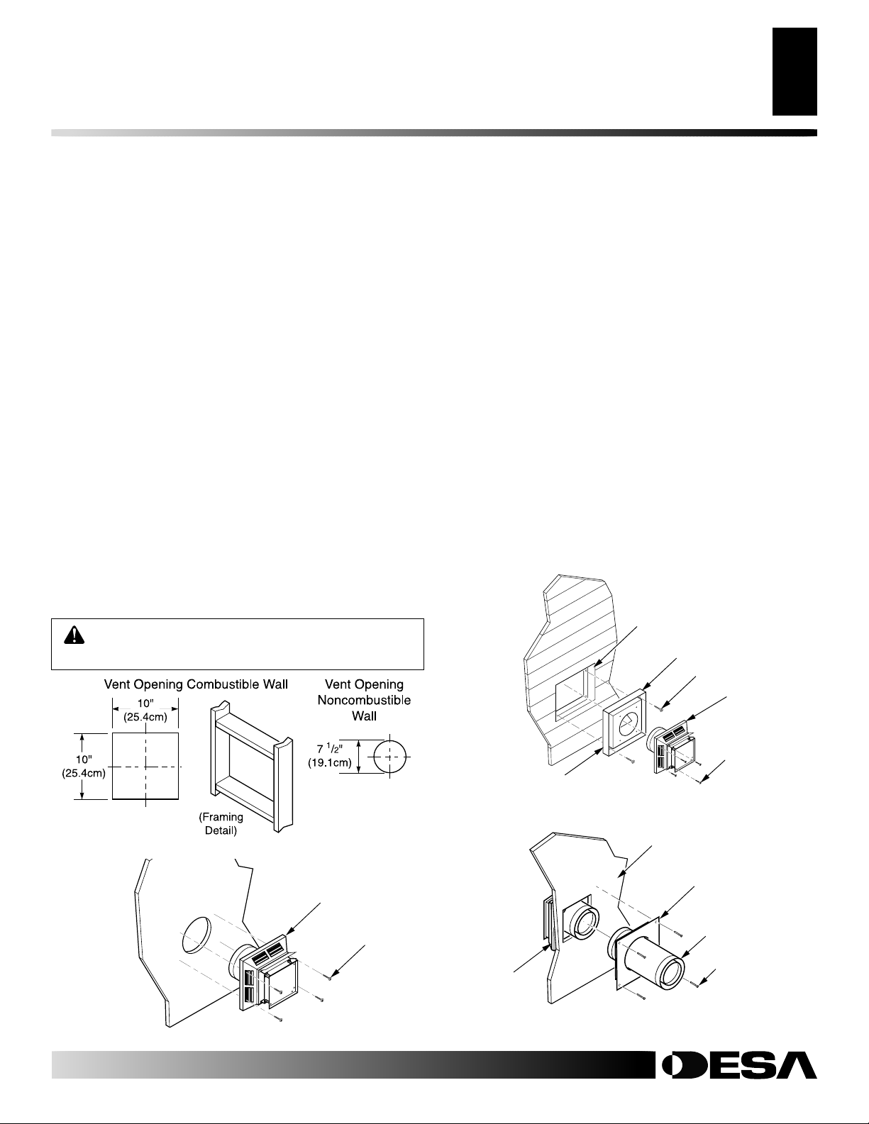
Mark the wall for a 10" square hole (for noncombustible material such as masonry block or concrete, a 7
1
/2" (19.1cm)
diameter hole is acceptable). See Figure 17. The center of
the hole should line up with the center-line of the horizontal
rigid vent pipe. Cut a 10"x10" (25.4cm x 25.4cm) square hole
through combustible exterior wall (7 1/2" [19.1cm] diameter
hole if noncombustible). Frame as necessary (see Figure 17).
4. Noncombustible Exterior Wall: Apply a bead of non-harden-
ing mastic around the outside edge of the vent cap. Position the
vent cap in the center of the 7 1/2" (19.1cm) hole on the exterior
wall with the arrow on the vent cap pointing up. Attach the vent
cap with four wood screws provided (see Figure 18).
Note
: Replace the wood screws with appropriate fasteners for stucco, brick,
concrete, or other types of siding.
WARNING: Do not recess vent termination in to
any wall. This will cause a fire hazard.
Combustible Exterior W all: For vinyl siding, stucco, or wood
exteriors, a siding standoff must be installed between the vent
cap and exterior wall. The siding standoff prevents excessive
heat from damaging siding materials. Siding materials must be
cut to accommodate standoff. Bolt the vent cap to the standoff. Apply non-hardening mastic around outside edge of the
standoff. Position the standoff/cap assembly in the center of
the 10" (25.4cm)square hole and attach to exterior wall with
wood screws provided (see Figure 19). The siding standoff must
sit flush against the exterior fascia material.
5.
Combustible Exterior Wall Only: Slide the interior wall
firestop over the vent pipe before connecting the horizontal
run to the vent cap (see Figure 20).
6. Carefully move the fireplace with vent assembly attached toward the wall and insert the vent pipe into the horizontal termination. The pipe overlap should be a minimum of 1 1/4" (3.2cm).
Fasten all vent pipe connections (except vent cap) with screws
provided. Refer to Framing on pages 5 and 6 for instructions
on securing unit to framing or floor.
7. Combustible Exterior Wall Only: Slide the wall firestop
against the interior wall surface and attach with screws provided (see Figure 20).
Cut Vinyl Siding
Away to Fit Standoff
Standoff
Wood Screw
Figure 17 - Vent Opening Requirements
Figure 18 - Installing Horizontal Vent Cap
For more information, visit www.desatech.com
For more information, visit www.desatech.com
106918-01B
Vent Cap
Wood Screw
Vent Cap
Apply Mastic
to All Four Sides
Figure 19 - Installing Vinyl Siding Standoff (Combustible Exterior
Wall)
Interior Wall
Surface
Vent Cap
(Horizontal
Termination)
Figure 20 - Connecting Vent Cap with Horizontal Vent Pipe
Bolt
Interior Wall Firestop
(Combustible
Exterior Wall Only)
Horizontal
Vent Pipe
Screw
 Loading...