

Page 1

CAST IRON STOVE AND DIRECT-VENT
(FREESTANDING FIREPLACE HEATER)
BURNER SYSTEM
OWNER’S OPERATION AND INSTALLATION MANUAL
For more information, visit www.desatech.com
For more information, visit www.desatech.com
SCIVFC/PSCIVFC
SERIES STOVE
"AMITY™"
VCIS/PVCIS
Series Stove
"OXFORD™"
NATURAL GAS BURNER SYSTEM MODEL SDVBND
PROPANE/LP GAS BURNER SYSTEM MODEL SDVBPD
REMOTE READY
IMPORTANT: This direct-vent burner system must be installed into approved cast iron
stove bodies, models SCIVFC/PSCIVFC/VCIS/PVCIS/VH series ONLY.
WARNING: If the information in this manual is not followed
exactly, a fire or explosion may result causing property
damage, personal injury, or loss of life.
FOR YOUR SAFETY
Do not store or use gasoline or other flammable vapors and
liquids in the vicinity of this or any other appliance.
FOR YOUR SAFETY
WHAT TO DO IF YOU SMELL GAS
• Do not try to light any appliance.
• Do not touch any electrical switch
• Do not use any phone in your building.
• Immediately call your gas supplier from a neighbor’s
phone. Follow the gas supplier’s instructions.
• If you cannot reach your gas supplier, call the fire department.
VH series Stove
"VICTOR HEARTH™"
WARNING: Improper installation, adjustment, alteration,
service, or maintenance can
cause injury or property damage. Refer to this manual for
correct installation and operational procedures. For assistance or additional information consult a qualified installer, service agency, or the
gas supplier.
Installation and service must
be performed by a qualified
installer, service agency, or
the gas supplier.
This appliance may be installed in an aftermarket*, permanently located, manufactured (mobile) home, where not prohibited by state or local codes.
This appliance is only for use with the type of gas indicated on the rating plate. This appliance
is not convertible for use with other gases, unless a certified kit is used.
* Aftermarket: Completion of sale, not for purpose of resale, from the manufacturer.
Save this manual for future reference.
Save this manual for future reference.
Page 2

TABLE OF CONTENTS
2
SAFETY INFORMATION
TABLE OF CONTENTS
SAFETY INFORMATION ............................................................ 2
PRODUCT IDENTIFICATION ..................................................... 3
LOCAL CODES ........................................................................... 4
PRODUCT FEATURES .............................................................. 4
GLOSSARY OF TERMS ............................................................. 4
PRE-INSTALLATION PREPARATION ........................................ 4
CAST IRON STOVE AND DIRECT-VENT BURNER SYSTEM
ASSEMBLY ................................................................................. 5
GENERAL VENTING ................................................................ 10
VENTING INSTALLATION ........................................................ 12
STOVE AND DIRECT-VENT BURNER SYSTEM INSTALLATION .. 20
OPERATING STOVE WITH BURNER SYSTEM ...................... 26
INSPECTING BURNERS.......................................................... 28
CLEANING AND MAINTENANCE ............................................ 29
TROUBLESHOOTING .............................................................. 30
SPECIFICATIONS .................................................................... 33
WIRING DIAGRAM ................................................................... 33
REPLACEMENT PARTS .......................................................... 33
ILLUSTRATED PARTS BREAKDOWN AND PARTS LIST ....... 34
TECHNICAL SERVICE ............................................................. 38
SERVICE HINTS....................................................................... 38
ACCESSORIES ........................................................................ 38
OWNER'S REGISTRATION ..................................................... 39
WARRANTY INFORMATION ...................................... Back Cover
SAFETY INFORMATION
WARNINGS
WARNING: This product contains and/or generates
chemicals known to the State of California to cause
cancer or birth defects, or other reproductive harm.
IMPORTANT: Read this owner’s manual carefully
and completely before trying to assemble, operate, or
service this stove and burner system. Improper use
of this stove and burner system can cause serious
injury or death from burns, fire, explosions, electrical
shock, and carbon monoxide poisoning.
DANGER: Carbon monoxide poisoning may lead
to death!
This appliance complies with the current ANSI Z21.88 and CSA 2.33
as a Vented Gas Fireplace Heater and is listed and tested by the
Canadian Standards Association to the above test standards. This stove
with burner system is a vented product. This stove with burner system
will not produce any gas leakage into your home if properly installed.
This stove with burner system must be properly installed by a qualified
service person. The glass door must be properly seated and sealed. If this
unit is not properly installed by a qualified service person with glass
door properly seated and sealed, gas leakage can occur.
Carbon Monoxide Poisoning: Early signs of carbon monoxide poison-
ing resemble the flu, with headaches, dizziness, or nausea. If you have
these signs, the stove may not have been installed properly. Get fresh air
at once! Have stove inspected and serviced by a qualified service person.
Some people are more affected by carbon monoxide than others. These
include pregnant women, people with heart or lung disease or anemia,
those under the influence of alcohol, and those at high altitudes.
Natural and Propane/LP Gas: Natural and propane/LP gases are
both odorless. An odor-making agent is added to each of these gases.
The odor helps you detect a gas leak. However, the odor added to
these gases can fade. Gas may be present even though no odor exists.
Make certain you read and understand all warnings. Keep this
manual for reference. It is your guide to safe and proper operation
of this stove and burner system.
WARNING: Any change to this stove or burner
system or its controls can be dangerous.
1. This appliance is only for use with the type of gas indicated on
the rating plate. This appliance is not convertible for use with
other gases unless a certified kit is used.
2. For propane/LP burner system, do not place propane/LP supply
tank(s) inside any structure. Locate propane/LP supply tank(s)
outdoors. To prevent performance problems, do not use propane/
LP fuel tank of less than 100 lbs. capacity (propane/LP units only).
3. If you smell gas
• shut off gas supply
• do not try to light any appliance
• do not touch any electrical switch; do not use any phone in
your building
• immediately call your gas supplier from a neighbor’s phone.
Follow the gas supplier’s instructions
• if you cannot reach you gas supplier, call the fire department.
4. Never install the stove
• in a recreational vehicle
• where curtains, furniture, clothing, or other flammable ob-
jects are less than 42" from the front, top, or sides of the stove
• in high traffic areas
• in windy or drafty areas
5. This stove reaches high temperatures. Keep children and adults
away from hot surfaces to avoid burns or clothing ignition. Stove
will remain hot for a time after shutdown. Allow surfaces to
cool before touching.
For more information, visit www.desatech.com
For more information, visit www.desatech.com
112126-01B
Page 3

SAFETY INFORMATION
PRODUCT IDENTIFICATION
3
3
SAFETY INFORMATION
Continued
6. Carefully supervise young children when they are in the room
with stove.
7. Do not modify the burner or stove under any circumstances. Any
parts removed for servicing must be replaced prior to operating
stove or burner system.
8. Turn burner system off and let cool before servicing, installing, or repairing. Only a qualified service person should install, service, or repair the stove or burner system. Have burner
system inspected annually by a qualified service person.
9. You must keep control compartments, burners, and circulating air passages clean. More frequent cleaning may be needed
due to excessive lint and dust from carpeting, bedding material, pet hair, etc. Turn off the gas valve and pilot light before
cleaning stove or burner system.
10. Have venting system inspected annually by a qualified service
person. If needed, have venting system cleaned or repaired.
See Cleaning and Maintenance, page 29.
11. Keep the area around your stove clear of combustible materials, gasoline, and other flammable vapor and liquids. Do not
run burner system where these are used or stored. Do not place
items such as clothing or decorations on or around stove.
12. Do not use this stove to cook food or burn paper or other objects.
13. Never place anything on top of stove.
14. Do not use any solid fuels (wood, coal, paper, cardboard, etc.)
in this stove. Use only the gas type indicated on burner system
nameplate.
15. This appliance, when installed, must be electrically grounded
in accordance with local codes or, in the absence of local codes,
with the National Electrical Code, ANSI/NFPA 70, or the Ca-
nadian Electrical Code, CSA C22.1.
16. Do not obstruct the flow of combustion and ventilation air in
any way. Provide adequate clearances around air openings into
the combustion chamber along with adequate accessibility
clearance for servicing and proper operation.
17. Do not install stove directly on carpeting, vinyl tile, or any combustible material other than wood. The stove must set on a metal
or wood panel extending the full width and depth of the stove.
18. Do not use stove or burner system if any part has been exposed to or under water. Immediately call a qualified service
person to arrange for replacement of the unit.
19. Do not operate burner system if any log is broken.
20. Do not use a blower insert, heat exchanger insert, or other accessory not approved for use with this stove.
21. Do not operate burner system with glass door removed, cracked,
or broken.
22. Provide adequate clearances to air openings.
PRODUCT IDENTIFICATION
Cast Iron
Stove Body
Log Set
T
O
L
I
P
L
O
I
T
P
HI
F
O
F
N
O
LO
IN
OUT
Piezo Ignitor
Vent
Opening
Rear
Cover
Pilot
Assy
Blower with
Adjustment
Knob (Optional
Installation)
Glowing
Embers
Grate Assembly
Figure 1 - DESA Direct-Vent Burner System Shown Installed in
Approved Cast Iron Stove Body (Oxford™ Model Shown)
Control Valve
Cast Iron
Stove Body
Stove
Front
Burner
Glass
Door Assy
Lava Rock
112126-01B
For more information, visit www.desatech.com
For more information, visit www.desatech.com
Page 4

LOCAL CODES
4
PRODUCT FEATURES
GLOSSARY OF TERMS
PRE-INSTALLATION PREPARATION
Location and Space Requirements
LOCAL CODES
Install and use stove and burner system with care. Follow all local
codes. In the absence to local codes, use the current National Fuel
Gas Code ANSI Z223.1/NFPA 54* (USA) or the current CSAB149[.1 or .2] Installation Codes (Canada).
*Available from:
American National Standards Institute, Inc.
1430 Broadway
New York, NY 10018
National Fire Protection Association, Inc.
Batterymarch Park
Quincy, MA 02269
PRODUCT FEATURES
OPERATION
This cast iron stove with burner system is clean burning and vents
easily through outside walls or vertically using outside air for
combustion. Heat is generated by both realistic flames and glowing
embers. When used without the blower accessory, the stove with
burner system requires no electricity making it ideal for emergency
backup heat.
PIEZO IGNITOR
This burner system has a piezo ignitor. This system requires no
matches, batteries, or other sources to light burner system.
GLOSSARY OF TERMS
Chase - A box-like enclosure to protect venting from the elements
when the venting run is on the outside of a structure.
Mastic - A pliable sealant for use around the vent terminal.
Snorkel Termination - A box that raises the horizontal termination
above ground level clearances.
Vent Termination - Mounted on an outside wall or roof to separate
the inlet and outlet of the vent system and protect it from weather.
Vinyl Siding Standoff - A metal box that separates the vent cap from
vinyl siding.
Wall Thimble/Firestop - A metal plate used to secure the vent pipe
when it passes through a wall or ceiling.
PRE-INSTALLATION
PREPARATION
WARNING: A qualified service person must in-
stall stove and burner system. Follow all local codes.
CAUTION: This stove creates warm air currents.
These currents move heat to wall surfaces next to
stove. Installing stove next to vinyl or cloth wall
coverings or operating stove where impurities (such
as, but not limited to, tobacco smoke, aromatic
candles, cleaning fluids, oil or kerosene lamps, etc.)
in the air exist, may discolor walls or cause odors.
LOCATION AND SPACE REQUIREMENTS
Determine the safest and most efficient location for your cast iron
stove. Make sure that rafters and wall studs are not in the way of the
venting system. Choose a location where the heat output is not
affected by drafts, air conditioning ducts, windows, or doors. Figure
2 shows some common locations. Read all venting information in this
manual. Be aware of all restrictions and precautions before deciding
the exact location for your stove.
When deciding the location of your stove, follow these rules:
1. Do not connect this stove and burner system to a chimney flue
serving a separate solid-fuel burning fireplace or appliance.
2. Due to high temperatures, do not locate this stove in high traffic areas or near furniture or draperies.
On Wall with
Horizontal Termination
On Wall with Vertical
Termination Through Ceiling
Corner Installation
Figure 2 - Common Stove Locations
For more information, visit www.desatech.com
For more information, visit www.desatech.com
112126-01B
Page 5

m
CAST IRON STOVE AND DIRECT-VENT BURNER SYSTEM ASSEMBLY
PRE-INSTALLATION
PREPARATION
Continued
3. Proper clearances must be maintained, see Figures 3 and 4.
4. This stove is a freestanding unit designed to set directly on the
floor. If your stove is to be installed directly on carpeting, vinyl tile, or any combustible material other than wood, it must
be installed on a metal or wood panel extending the full width
and depth of the stove. See Figure 5.
Ceiling
PRE-INSTALLATION PREPARATION
Location and Space Requirements (Cont.)
Stove Body Assembly
26 1/4"
Front
1
19
/2"
5
5
42"
(106.68 cm)
36"
(91.44 cm)
from
Front
Floor
(15.24 cm)
29"
(73.66 cm)
6
"
4"
(10.16 cm)
from
Back
Wall
Front
27"
4
"
(10.16 c
Figure 3 - Clearances for Standard Installation
Figure 5 - Stove With Burner System Bottom Dimensions
CAST IRON STOVE AND
DIRECT-VENT BURNER
SYSTEM ASSEMBLY
STOVE BODY ASSEMBLY
1. Lift off corrugated box enclosing stove body crating.
2. Remove all screws fastening the wood frame enclosure. Spread
wood frame open and lift away from plastic-bagged stove body.
The bottom pieces of pallet wood will remain bolted to the
stove body.
3. Remove plastic bag from stove body.
4. Locate the product identification label on the carton and record
the model number and 7 digit serial number in the space provided in the back of this owner’s manual. Retain this operation and installation manual for future reference and warranty.
5. Amity Only:Remove the six (6) bolts on the back stove panel
with an adjustable wrench or a 10 mm socket. Discard the back
panel and retain the bolts and washers to attach the rear cover
provided with the burner system.
4"
(10.16
cm)
Figure 4 - Clearance for Corner Installation
For more information, visit www.desatech.com
For more information, visit www.desatech.com
112126-01B
4"
(10.16
Bolt
Back Stove
Panel
cm)
Figure 6 - Removing Back Panel (Amity Stove Only)
Page 6

CAST IRON STOVE AND DIRECT-VENT BURNER SYSTEM ASSEMBLY
6
Stove Body Assembly (Cont.)
CAST IRON STOVE AND
DIRECT-VENT BURNER
SYSTEM ASSEMBLY
Continued
6. Remove all contents from inside stove cavity. Contents include:
(1) - Stove bottom [Amity Only] (Discard - Not used with
this application)
(4) - Legs with leg leveler bolts
(1) - Bottom door
(3) - Top grates
(1) - Hardware kit bag with fasteners
7. Carefully lay stove body on back to attach bottom components to
stove body (see Figure 7). Rest stove on drop cloth or blanket to
avoid scratching stove edges.
8. Remove remaining pallet wood attached to bottom of stove
body (see Figure 8). Use an adjustable wrench to remove bolts.
9. Fasten each leg to stove with four (4) M8 x 1.25 - 20mm bolts.
Use a flat washer and lock washer with each bolt. Tighten bolts
into threaded holes on stove body (see Figures 9 and 10). Use
an adjustable wrench or a 12mm and 6mm socket.
10. Attach stove door by inserting step bolt through door hinge pivot
hole and into threaded hole in stove body (Figures 9 and 11). Use
an adjustable wrench or a 12mm socket to fasten step bolt. Tighten
step bolt until snug. Make sure door moves freely.
Top of Stove Unit
Top of
Stove
Unit
Front of
Stove
Unit
Drop
Cloth/
Blanket
Front of
Stove Unit
Pallet
Wood
Bolted to
Bottom of
Stove Body
11. Install door catch bolt (M8 x 1.25-55mm with two M8 hex nuts)
into threaded hole on stove body (see Figure 9). Use an adjustable wrench or a 12mm socket. The catch bolt has two hex nuts
attached to it (see Figure 12). The top nut is a bolt stop and the
bottom nut is for door leveling adjustment.
Door Hinge Step
Bolt Hole
Bottom of
Stove Unit
Figure 9 - Locating Threaded Holes for Legs and Door Attachment
Washers
Bolt
Figure 10 - Attaching Stove Legs (Oxford™ Model Shown)
Front
Leg Hole
Door Catch Bolt
With Adjustable
Hex Nuts Hole
Bottom Of
Stove Unit
Leg
Figure 7 - Laying Down Stove On Side
Front
Bolt
Pallet
Wood
Figure 8 - Removing Pallet Wood From The Bottom of The Stove
For more information, visit www.desatech.com
For more information, visit www.desatech.com
Pallet
Wood
Bottom Of
Stove Unit
Stove Door
Door Hinge
Step
Bolt
Bolt Shoulder
Figure 11 - Attaching Stove Door
Threaded
Hole
Door
Door Claw
Catch
Bolt
Figure 12 - Catch Bolt and
Door Claw Orientation
Bolt Stop
Adjusting
Nut
112126-01B
Page 7

CAST IRON STOVE AND DIRECT-VENT BURNER SYSTEM ASSEMBLY
CAST IRON STOVE AND
DIRECT-VENT BURNER
SYSTEM ASSEMBLY
Continued
12. Check general catch bolt alignment with door claw. Make final adjustment and door leveling after stove is in normal standing position.
13. Carefully lift stove back up on its four attached legs.
Removing Front Surround Panel
Remove 2 bolts from bottom of stove and set aside. Remove bolt from
the top of the stove to remove the front panel assembly (see Figure 13).
Stove
Body
Front
Assembly
Bolt
Installing Direct-Vent Burner System Into Stove Body
Front
Surround
Plate
Stove Body Assembly (Cont.)
Screws
Screw with
Washer
Screw with
Washer
Screen
Screen
Front Surround
Plate and
Front Plate
Amity™ Model
Doors
Oxford™ and Victor Hearth™
Model
Figure 14 - Removing Screen from Front Assembly
7
7
Figure 13 - Removing Front Assembly (Oxford™ Model Shown)
Removing Screen (Optional)
Amity Models
1. Lay the front panel assembly face down on a protected surface. Remove the two screws that hold the front plate onto the
front surround plate (see Figure 14). Save these screws.
2. Remove the screws and washers that hold the screen onto the
front surround plate. Discard these screws, washers, and screen
(see Figure 14).
3. Replace the two screws from step 1 to reassemble the front
plate and the front surround plate. Set this assembly aside until burner system has been installed, logs have been placed
inside of burner system, and glass door to burner system insert
has been replaced.
Oxford or Victor Hearth Models
1. Lay the front panel assembly face down on a protected surface. Remove the screws and washers that hold the screen onto
the front surround plate. Discard these screws, washers, and
screen (see Figure 14).
2. Set this assembly aside until burner system has been installed,
logs have been placed inside of burner system, and glass door
to burner system insert has been replaced.
INSTALLING DIRECT-VENT BURNER
SYSTEM INTO STOVE BODY
1. Carefully lift burner system and place into stove body from
the rear of stove.
2. Place the left and right grate tops into the top of stove body. Discard center grate top of stove and replace with center grate top
provided with burner system.
Right Top
Center Top Grate
(Included with
Burner System)
Left Top
Grate
Figure 15 - Installing Burner System Into Cast Iron Stove Body
Grate
O
L
H
I
P
FF
I
O
L
O
O
T
N
Cast Iron
Stove Body
Burner
System
112126-01B
For more information, visit www.desatech.com
For more information, visit www.desatech.com
Page 8

CAST IRON STOVE AND DIRECT-VENT BURNER SYSTEM ASSEMBLY
8
Installing Optional Blower Accessory
CAST IRON STOVE AND
DIRECT-VENT BURNER
SYSTEM ASSEMBLY
Continued
INSTALLING OPTIONAL BLOWER
ACCESSORY
NOTICE: If installing blower in an existing stove
burner system with gas connections, shut off gas
supply and disconnect heater from gas supply. Contact a qualified service person to do this.
INSTALLING THE BLOWER
1. Remove 4 hex screws securing rear cover to back of stove body
(see Figure 16).
2. Separate bottom cover from rear cover by loosening the 8
mounting screws (see Figure 16).
3. Align the holes in the top mounting tabs of blower with the
holes in wall of rear cover. Using the 4 screws provided, mount
blower and tighten screws securely (see Figure 17).
Rear Cover
Hex Screws
Stove Body
Mounting
Screws
Thermostat Blower Only: Attach thermal switch and bracket
4.
to inside rear cover wall with two hex head screws provided as
shown in Figure 17. After securing bracket to rear cover, carefully bend along existing bend line on bracket to almost a 90°
angle (see Figure 17). This will allow thermal switch to be
positioned against stove rear wall and sense temperature when
in operating mode.
5. Place speed control on left inside of rear cover and push the
plastic control shaft through opening (see Figure 17).
6. While supporting speed control, secure control shaft with lock
nut by pushing and turning lock nut with pliers clockwise until tight against the side of rear cover. Place control knob provided onto shaft.
TOP VIEW
Thermal
Switch and
Bracket
Blower
Control
Knob
Locknut
Control
Shaft
Speed
Control
Hex
Screws
Mounting
Screws
Bottom Cover
Figure 16 - Removing Rear Cover and Bottom Cover from Stove
Body
Mounting
Screws
Screws
Mounting
Holes
Blower
Assembly
Figure 17 - Blower Assembly, Speed Control, and Thermal
Switch Locations
Mounting Holes
For more information, visit www.desatech.com
For more information, visit www.desatech.com
112126-01B
Page 9

CAST IRON STOVE AND DIRECT-VENT BURNER SYSTEM ASSEMBLY
CAST IRON STOVE AND
DIRECT-VENT BURNER
SYSTEM ASSEMBLY
Continued
7. Place the green ground wire between the bottom hole on the
blower assembly and the hex screw and tighten (see Figure 18).
8. Connect the blue wire on the blower assembly to one side of
the thermal switch (see Figure 18).
9. Connect the black wire to the other side of the thermal switch
(see Figure 18).
10. Connect the white wire to the other terminal on the blower motor assembly (see Figure 18). Make sure the thermal switch has
been properly installed to fit against back of fireplace insert after the rear cover assembly has been reinstalled.
11. Make sure all wire connections to terminals on blower motor
and thermal switch are securely attached and that the screw
retaining the green ground wire is tight.
12. Check to make sure that the power cord is completely clear of the
blower wheel and that there are no foreign objects in blower wheel.
13. Peel off the backing paper and stick the supplied wiring diagram decal on the inside of rear cover as shown (see Figure 18).
WARNING: Never touch the blower wheel while in
operation.
Speed
Control
Power Cord (Route Through
Plastic Bushing in Bottom
Cover When Assembled)
9
Installing Optional Blower Accessory (Cont.)
Installing Rear Cover
9
14. Reattach bottom cover to rear cover with 8 screws (see Figure
16, page 8). Make sure that you don’t pinch any wires during
reassembly. Route power cord through plastic bushing in bottom of rear cover.
WARNING: Failure to position the parts in accordance with supplied diagrams or failure to use only
parts specifically approved with this heater may result
in damage or personal injury.
INSTALLING REAR COVER
1. Place rear cover behind stove body. Rear cover will rest on the
bottom ledge of the stove body.
2. Using hex screws provided, attach rear cover to back of stove
body. See Figure 19.
securely in place before venting pipes are installed.
3. Open lower door panel. The valve is attached to the underside
of the burner system assembly.
4. Connect or reconnect gas supply, see Connecting Stove/Burner
System to Gas Supply on page 21.
WARNING: A qualified installer or service person must connect fireplace to gas supply. Follow all
local codes.
IMPORTANT:
This rear cover must be
Black
Wire
Thermal
Switch
Wiring
Diagram
Blue Wire
Screw
Green Ground Wire
Figure 18 - Blower Wiring Layout (Thermostat Blower Shown)
For more information, visit www.desatech.com
For more information, visit www.desatech.com
112126-01B
White
Wire
Decal
Hex Screws
Rear Cover
(Shown with
Optional
Blower
Power
Cord
Figure 19 - Installing Rear Cover (Shown with Optional Blower
Accessory)
Blower)
Page 10

GENERAL VENTING
10
Location of Vent Termination
GENERAL VENTING
Your stove with burner system is approved to be vented either
through the side wall, or vertically using the following guidelines:
• Use only venting components or kits specifically approved for
use with this stove and burner system (see Parts Lists for Vent-
ing Kits and Components, page 19).
IMPORTANT:
ent manufacturers.
• Minimum clearance between vent pipes and combustible materials is 1" (2.5 cm), except where stated otherwise.
• Do not recess venting terminations into a wall or siding.
• Install horizontal venting with a 1/4" rise for every 12" of
run toward the termination.
• You may paint the vent termination with 450ºF (232ºC) heatresistant paint to coordinate with the exterior finish.
• There must not be any obstruction such as bushes, garden sheds,
fences, decks, or utility buildings within 24" from the front of
the termination cap.
• Do not locate termination cap where excessive snow or ice build
up may occur. Be sure to clear vent termination area after snow
falls to prevent accidental blockage of venting system. When
using snow blowers, do not direct snow towards vent termination area.
• You must maintain minimum wall and ceiling clearances shown
in Figures 3 and 4, page 5.
• If installing horizontal vent termination cap on an exterior wall
with siding, you must us a vinyl siding standoff (see Figure 26,
page 14).
Do not mix venting components made by differ-
LOCATION OF VENT TERMINATION
When locating vent termination, it is important to observe the
minimum clearances shown in Figure 20, page 11.
*Check with local codes or with the current CAN/CSA B149[.1 or .2]
Installation Codes for Canada or the USA Installations follow the
current National Fuel Gas Code, ANSI Z223.1/NFPA 54.
For more information, visit www.desatech.com
For more information, visit www.desatech.com
112126-01B
Page 11

GENERAL VENTING Continued
D
E
V
B
L
F
V
A = clearance above grade, veranda, porch, deck, or balcony
[*12 inches (30.5mc) minimum]
B = clearance to window or door that may be opened
[12 inches (30.5cm) minimum]
C = clearance to permanently closed window [minimum 12 inches
(30.5cm) recommended to prevent condensation on window]
D = vertical clearance to ventilated soffit located above the terminal
within a horizontal distance of 24 inches (61cm) from the
center-line of the terminal [18 inches (45.7cm) minimum]
E = clearance to unventilated soffit [12 inches (30.5cm) minimum]
F = clearance to outside corner (see below)
G = clearance to inside corner (see below)
H = *not to be installed above a meter/regulator assembly within
36 inches (91.4cm) horizontally from the center-line of the regulator
vent shall not terminate directly above a side-walk or paved driveway which is located between two
single family dwellings and serves both dwellings*
only permitted if veranda, porch, deck or balconey is fully open on a minimum of 2 sides beneath the floor*
* as specified in CAN/CSA B149 (.1 or .2) Installation Codes (1991) for Canada and U.S.A.
Note
: Local codes or regulations may require different clearances
C
Fixed
Closed
Openable
V
B
TERMINATION CAP
V
Openable
B
AIR SUPPLY INLET
X
GENERAL VENTING
N
H
B
Fixed
Closed
V
A
V
B
J
X
G
I = clearance to service regulator vent outlet [*72 inches (182.9cm)
minimum]
J = clearance to non-mechanical air supply inlet to building or the
combustion air inlet to any other fireplace [*12 inches (30.5cm)
minimum]
K = clearance to a mechanical air supply inlet [*72 inches (182.9cm)
minimum]
L = clearance above paved side-walk or a paved driveway located on
public property [*84 inches (213.3cm) minimum]
M = clearance under veranda, porch, deck [*12 inches (30.5cm) minimum ]
N = clearance above a roof shall extend a minimum of 24 inches (61cm)
above the highest point when it passes through the roof surface and
any other obstruction within a horizontal distance of 18 inches (45.7cm)
G
GAS METER RESTRICTED AREA
I
M
V
K
(TERMINATION PROHIBITED)
11
11
N
G
V
G
X
V
A
Termination Clearances for Buildings with Combustible and Noncombustible Exteriors
Inside Corner
A
Balcony with No Side Wall
G = 12" (30.5cm) minimum clearance
A = 6" (15.2cm)
V
G
V
Outside Corner Recessed Location
V
B = 6" (15.2cm)
B
Balcony with Perpendicular Side Wall
H
V
J
Combustible &
Noncombustible
H = 24" (61cm)
J = 20" (50.8cm)
Figure 20 - Minimum Clearances for Vent Terminations
For more information, visit www.desatech.com
For more information, visit www.desatech.com
112126-01B
D
C
V
C = Maximum depth of 48" (121.9cm) for
recessed location
D = Minimum width for back wall of
recessed location Combustible - 38" (965mm)
Noncombustible - 24" (61cm)
E = Clearance from corner in
recessed locationCombustible - 6" (15.2cm)
Noncombustible - 2" (5.1cm)
C
E
Page 12

12
VENTING INSTALLATION
Installation Precautions
Installation Planning
VENTING INSTALLATION
WARNING: Read all instructions completely and
thoroughly before attempting installation. Failure to
do so could result in serious injury, property damage
or loss of life. Operation of improperly installed and
maintained venting system could result in serious
injury, property damage or loss of life.
NOTICE: Do not seal termination cap to pipe. Cap
must be removable for servicing vent system.
NOTICE: Failure to follow these instructions will void
the warranty.
INSTALLATION PRECAUTIONS
Consult local building codes before beginning the installation. The
installer must make sure to select the proper vent system for installation. Before installing vent kit, the installer must read this stove and
burner system manual and vent kit instructions.
Only a qualified service person should install venting system. The
installer must follow these safety rules:
• Wear gloves and safety glasses for protection
• Use extreme caution when using ladders or when on roof tops
• Be aware of electrical wiring locations in walls and ceilings
The following actions will void the warranty on your venting system:
• Installation of any damaged venting component
• Unauthorized modification of the venting system
• Installation of any component part not manufactured or approved
by DESA
• Installation other than as instructed by these instructions
WARNING: This stove with burner system and
vent assembly must be vented directly to the outside.
The venting system must NEVER be attached to a
chimney serving a separate solid fuel burning appliance. Each gas appliance must use a separate vent
system. Do not use common vent systems.
INSTALLATION PLANNING
There are two basic types of direct-vent installation:
• Horizontal Termination
• Vertical Termination
It is important to select the proper length of vent pipe for the type of
termination you choose. It is also important to note the wall thickness.
For Horizontal Termination: Select the amount of vertical rise
desired. The horizontal run of venting must have 1/4" rise for every
12" of run towards the termination.
WARNING: Never run the vent pipe downward as
this may cause excessive temperatures which could
cause a fire.
You may use up to two 90° elbows on any single horizontal run of
vent pipe in this configuration. See Horizontal Termination Configu-
rations, and Figures 28 and 30 on page 15.
For Vertical Termination: Measure the distance from the burner
system flue outlet to the ceiling. Add the ceiling thickness, the vertical
rise in an attic or second story, and allow for sufficient vent height
above the roofline. You may use up to three 90° elbows, depending
on venting configuration. See Vertical Termination Configurations
on page 17.
Note:
You may use up to two 45° elbows in place of a 90° elbow.
You must follow rise to run ratios when using 45° elbows.
For two-story applications, firestops are required at each floor level
(see Figure 32, page 16). If an offset is needed in the attic, additional
pipe and elbows will be required.
You may use a chase with a vent termination with exposed pipe on the
exterior of the house. See Installing Vent System in a Chase, page 13.
Your stove with direct-vent burner system has been tested for a
maximum horizontal run of 20' with 8' vertical rise (see Installation
for Horizontal Termination, page 13). The maximum vertical run is
40' (see Installation for Vertical Termination, page 16).
It is very important that the venting system maintain its balance
between the combustion air intake and the flue gas exhaust. Certain
limitations apply to vent configurations and must be strictly followed.
WARNING: Horizontal sections of this vent system
require a minimum clearance of 2" from the top of the
pipe and 1" minimum to the sides and bottom. Vertical
sections of this system require a minimum of 1" clearance to combustible materials on all sides of the pipe.
For more information, visit www.desatech.com
For more information, visit www.desatech.com
112126-01B
Page 13

VENTING INSTALLATION
Continued
Installing Vent System in a Chase
A chase is a vertical box-like structure built to enclose venting that runs
along the outside of a building. A chase is not required for such venting.
NOTICE: Treatment of firestops and construction of
the chase may vary from building type to building
type. These instructions are not substitutes for the
requirements of local building codes. You must follow all local building codes.
Note:
When installing in a chase, you should insulate the chase as
you would the outside walls of your home. This is especially
important in cold climates. Minimum air space clearance between
vent pipes and combustible materials and/or insulation is 1".
INSTALLATION FOR HORIZONTAL
TERMINATION
VENTING INSTALLATION
Installation Planning (Cont.)
Installation for Horizontal Termination
Figure 21 - Snorkel Termination
Snorkel
12" Minimum
(30.5cm)
13
13
CAUTION: Horizontally terminated venting configurations require one foot of vertical rise from the 45°
elbow before any horizontal run can be made. Failure
to meet venting requirements may cause performance
problems and possible damage to the fireplace.
1. Determine the route your horizontal venting will take.
location of the horizontal vent termination on the exterior wall
must meet all local and national building codes and must not be
blocked or obstructed.
WARNING: Do not recess vent terminal into a wall
or siding.
Snorkel terminations are available for terminations requiring a
vertical rise on the exterior of the building (see Figures 21 and
22). Snorkel kit VKS-47-K is also available (see page 19). Follow the same installation procedures used for standard horizontal termination with the exception of the external wall firestop.
The snorkel termination does not require the use of the external
wall firestop. If installing the snorkel termination below grade
(basement applications), you must provide proper drainage to
prevent water from entering the snorkel termination (see Figure
22). Do not back fill around the snorkel termination.
2. Vent pipes and fittings have special twist-lock connections. Assemble the desired combination of pipe and elbows to the appliance adaptor with pipe seams oriented towards the wall or floor.
Twist-lock Procedure: The female ends of the pipes and fittings
have four locking lugs (indentations). These lugs will slide straight
into matching slots on the male ends of adjacent pipes and fittings.
(All connections must be sealed with high temperature silicone
sealant as specified in the second warning statement on page 12.)
Push the pipe sections together and twist one section clockwise
approximately one-quarter turn until the sections are fully locked.
See Figure 23.
every three feet. Use wall straps for this purpose.
Note:
Horizontal runs of vent must be supported
Note:
The
Snorkel
12" Minimum
(30.5cm)
Adequate
drainage
Figure 22 - Snorkel Termination with Drainage Pipe
Female
Locking Lugs
Male
Slots
Vent Pipe
Figure 23 - Vent Pipe Connections
112126-01B
For more information, visit www.desatech.com
For more information, visit www.desatech.com
Page 14
14
VENTING INSTALLATION
Installation for Horizontal Termination (Cont.)
VENTING INSTALLATION
Continued
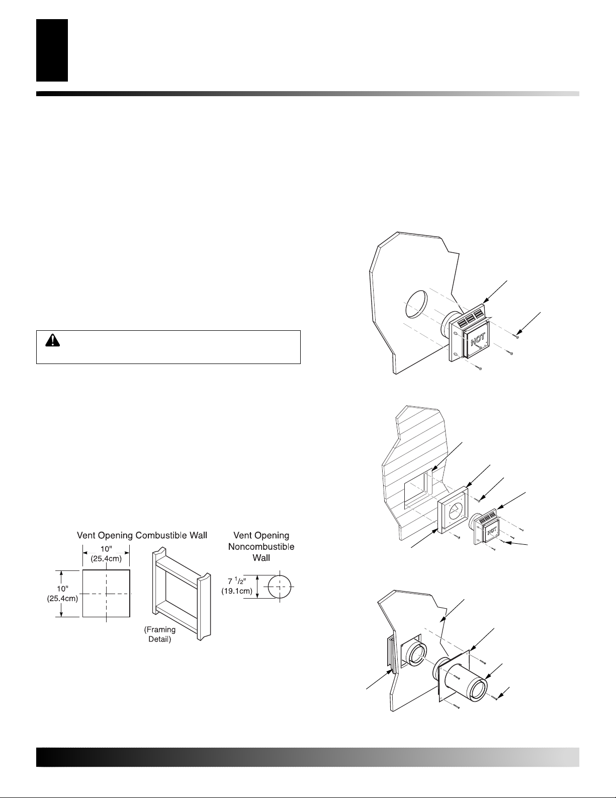
3. Attach vent pipe assembly to the burner system. Set stove in
front of it’s permanent location to insure minimum clearances.
Mark the wall for a 10"(25.4cm) square hole (for noncombustible material such as masonry block or concrete, a 7
1
/2" (19.1cm)
diameter hole is acceptable). See Figure 24. The center of the
hole should line up with the center-line of the horizontal rigid
vent pipe. Cut a 10"x10" (25.4cm x 25.4cm) square hole through
combustible exterior wall (7 1/2" [19.1cm] diameter hole if
noncombustible). Frame as necessary (see Figure 24).
4. Noncombustible Exterior Wall: Apply a bead of non-harden-
ing mastic around the outside edge of the vent cap. Position the
vent cap in the center of the 7 1/2" (19.1cm) hole on the exterior
wall with the arrow on the vent cap pointing up. Attach the vent
cap with four wood screws provided (see Figure 25).
Note
: Replace the wood screws with appropriate fasteners for stucco, brick,
concrete, or other types of siding.
WARNING: Do not recess vent termination in to
any wall. This will cause a fire hazard.
Combustible Exterior Wall: For vinyl siding, stucco, or wood
exteriors, a siding standoff must be installed between the vent
cap and exterior wall. The siding standoff prevents excessive
heat from damaging siding materials. Siding materials must be
cut to accommodate standoff. Bolt the vent cap to the standoff. Apply non-hardening mastic around outside edge of the
standoff. Position the standoff/cap assembly in the center of
the 10" (25.4cm) square hole and attach to exterior wall with
wood screws provided (see Figure 26). The siding standoff must
sit flush against the exterior fascia material.
5. Combustible Exterior Wall Only: Slide the interior wall
firestop over the vent pipe before connecting the horizontal
run to the vent cap (see Figure 27).
6. Carefully move the fireplace with vent assembly attached toward
the wall and insert the vent pipe into the horizontal termination.
The pipe overlap should be a minimum of 1 1/4" (3.2cm). Fasten
all vent pipe connections (except vent cap) with screws provided.
7. Combustible Exterior Wall Only: Slide the wall firestop
against the interior wall surface and attach with screws provided (see Figure 27).
Vent Cap
Wood Screw
Figure 25 - Installing Horizontal Vent Cap (Noncombustible
Exterior)
Cut Vinyl Siding
Away to Fit Standoff
Standoff
Wood Screw
Vent Cap
Figure 24 - Vent Opening Requirements
For more information, visit www.desatech.com
For more information, visit www.desatech.com
Apply Mastic
to All Four Sides
Figure 26 - Installing Vinyl Siding Standoff (Combustible Exterior
Wall)
Interior Wall
Surface
Interior Wall Firestop
(Combustible
Exterior Wall Only)
Vent Cap
(Horizontal
Termination)
Figure 27 - Connecting Vent Cap with Horizontal Vent Pipe
Bolt
Horizontal
Vent Pipe
Screw
112126-01B
Page 15
Installation for Horizontal Termination (Cont.)
VENTING INSTALLATION
15
15
VENTING INSTALLATION
Continued
Horizontal Termination Configurations
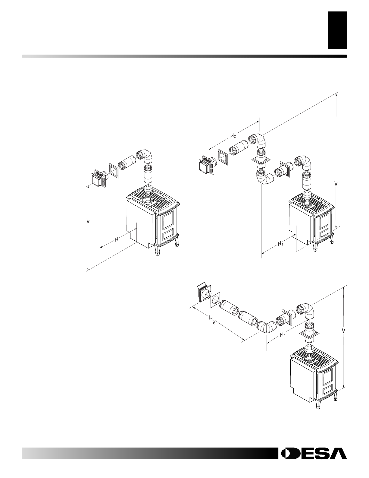
Figures 28 through 30 show different configurations for venting
with horizontal termination. Each figure includes a chart with
vertical minimum/maximum and horizontal maximum dimensions
which must be met. Seal all connections with high temperature
silicone sealant (outer pipe only) as specified in the second warning
statement on page 12. All horizontal piping runs require 1/4" rise per
12" of horizontal run.
Horizontal Venting
Vertical (V) Horizontal (H)
52" min. 26" max.
63" min. 49" max.
86" min. 96" max.
91" min. 20' max.
Venting with Three 90° Elbows
Vertical (V) Horizontal (H
6' min. 4' max. 8' max.
7' min. 6' max. 12' max.
8' min. 8' min. 20' max.
20' max. 8' max. 20' max.
) Horizontal (H1) +
1
Horizontal (H2)
Figure 28 - Horizontal Termination Configuration for Venting
Using One 90
°
Elbow
Figure 29 - Horizontal Termination Configuration for Venting
Using Three 90° Elbows
Venting with Two 90° Elbows
Vertical (V) Horizontal (H1) +
Horizontal (H2)
6' min. 4' max.
7' min. 6' max.
8' min. 10' max.
20' max. 12' max.
Figure 30 - Horizontal Termination Configuration for Venting
Using Two 90° Elbows with Termination at 90° with Stove
112126-01B
For more information, visit www.desatech.com
For more information, visit www.desatech.com
Page 16
16
VENTING INSTALLATION
Installation for Vertical Termination
VENTING INSTALLATION
Continued
INSTALLATION FOR VERTICAL
TERMINATION
NOTICE: Use rigid pipe only. Flex venting is not to be
used with a vertical termination.
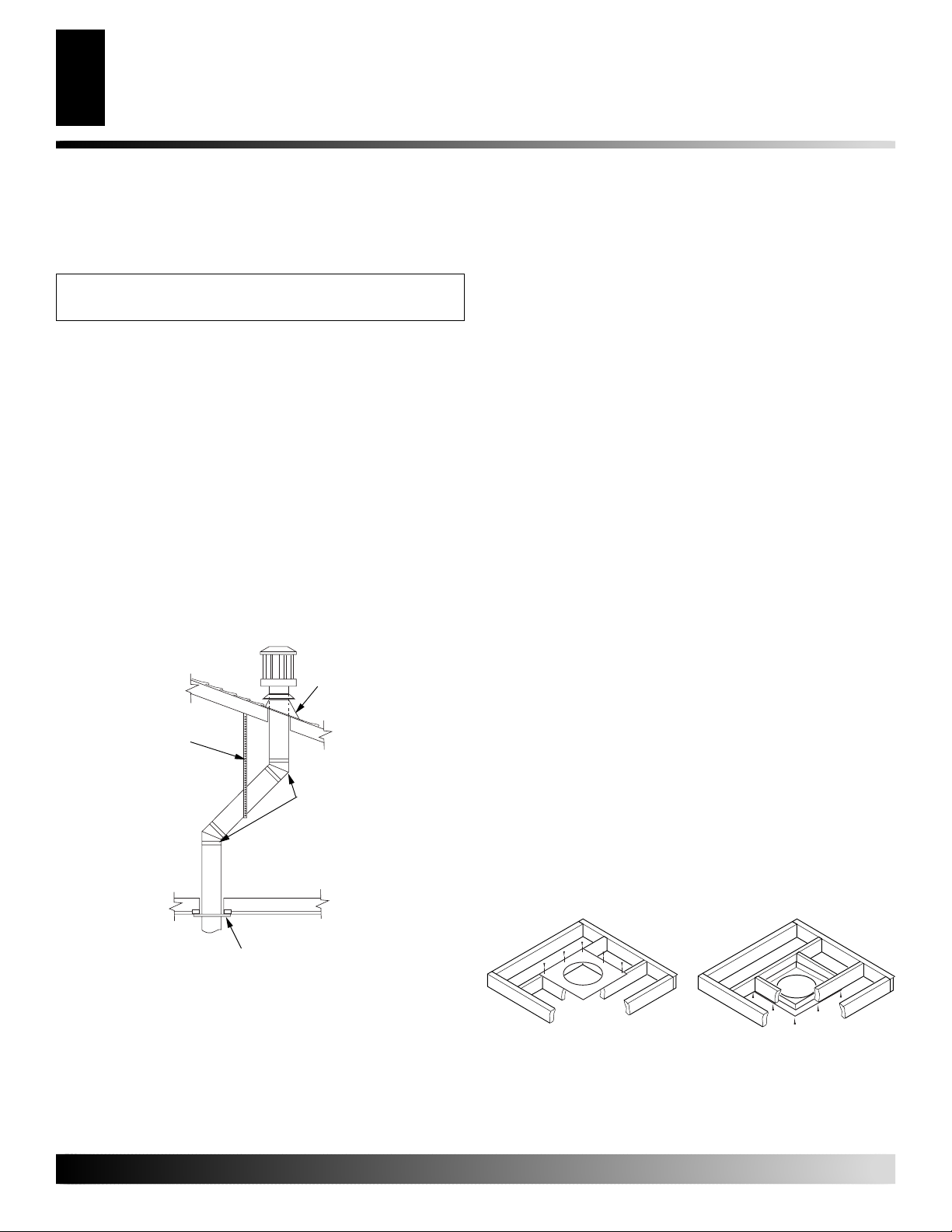
1. Determine the route your vertical venting will take. If ceiling
joists, roof rafters, or other framing will obstruct the venting
system, consider an offset (see Figure 31) to avoid cutting load
bearing members.
tion instructions for required clearances (air space) to combustibles when passing through ceilings, walls, roofs, enclosures,
attic rafters, etc. Do not pack air spaces with insulation. Also
note maximum vertical rise of the venting system and any maximum horizontal offset limitations. Offsets must fall within the
parameters shown in Figures 35 through 37, pages 17 and 18.
2. Set the stove in desired location. Drop a plumb line down from
the ceiling to the position of the burner system exit flue. Mark
the center point where the vent will penetrate the ceiling. Drill
a small locating hole at this point.
Drop a plumb line from the inside of the roof to the locating
hole in the ceiling. Mark the center point where the vent will
penetrate the roof. Drill a small locating hole at this point.
Wall Strap
Note:
Pay special attention to these installa-
Roof
Flashing
45° Elbow
Flat Ceiling Installation
1. Cut a 10" (25.4cm) square hole in the ceiling using the locating hole as a center point. The opening should be framed to
10"x10" (25.4cm x 25.4cm) inside dimensions, as shown in
Figure 24 on page 14 using framing lumber the same size as
the ceiling joists. If the area above the ceiling is an insulated
ceiling or a room, nail firestop from the top side. This prevents loose insulation from falling into the required clearance space. Otherwise, install firestop below the framed hole.
The firestop should be installed with no less than three nails
per side (see Figure 32).
2. Assemble the desired lengths of pipe and elbows necessary
to reach from the burner system flue up through the firestop.
All connections must be sealed with high temperature silicone sealant as specified in the second warning statement on
page 12. Be sure all pipe and elbow connections are fully
twist-locked (see Figure 23, page 13).
3. Cut a hole in the roof using the locating hole as a center point.
(Cover any exposed open vent pipes before cutting hole in roof.)
The 10"x10" (25.4cm x 25.4cm) hole must be measured on
the horizontal; actual length may be larger depending on the
pitch of the roof. There must be a 1" clearance from the vent
pipe to combustible materials. Frame the opening as shown in
Figure 24 on page 14.
4. Connect a section of pipe and extend up through the hole.
Note:
If an offset is needed to avoid obstructions, you must
support the vent pipe every 3 feet. Use wall straps for this
purpose (see Figure 31). Whenever possible, use 45° elbows
instead of 90° elbows. The 45° elbow offers less restriction
to the flow of the flue gases and intake air.
5. Place the flashing over the pipe section(s) extending through
the roof. Secure the base of the flashing to the roof and framing with roofing nails. Be sure roofing material overlaps the
top edge of the flashing as shown in Figure 31. There must be
a 1" clearance from the vent pipe to combustible materials.
If area above is a room, install
firestop above framed hole.
If area above is not a
room, install firestop below
framed hole.
Ceiling Firestop
Figure 31 - Offset with Wall Strap and 45° Elbows
For more information, visit www.desatech.com
For more information, visit www.desatech.com
Figure 32 - Installing Firestop
112126-01B
Page 17
VENTING INSTALLATION
Continued
6. Continue to add pipe sections until the height of the vent cap
meets the minimum building code requirements described in
Figure 20 on page 11.
steep roof pitches. Nearby trees, adjoining rooflines, steep
pitched roofs, and other similar factors may cause poor draft
or down-drafting in high winds. Increasing the vent height may
solve this problem.
7. Twist-lock the vent cap onto the last section of vent pipe and
seal outer pipe connection with high temperature silicone sealant as specified in the second warning statement on page 12.
Note:
If the vent pipe passes through any occupied areas above the first
floor, including storage spaces and closets, you must enclose pipe. You
may frame and sheetrock the enclosure with standard construction
material. Make sure and meet the minimum allowable clearances to
combustibles. Do not fill any of the required air spaces with insulation.
Cathedral Ceiling Installation
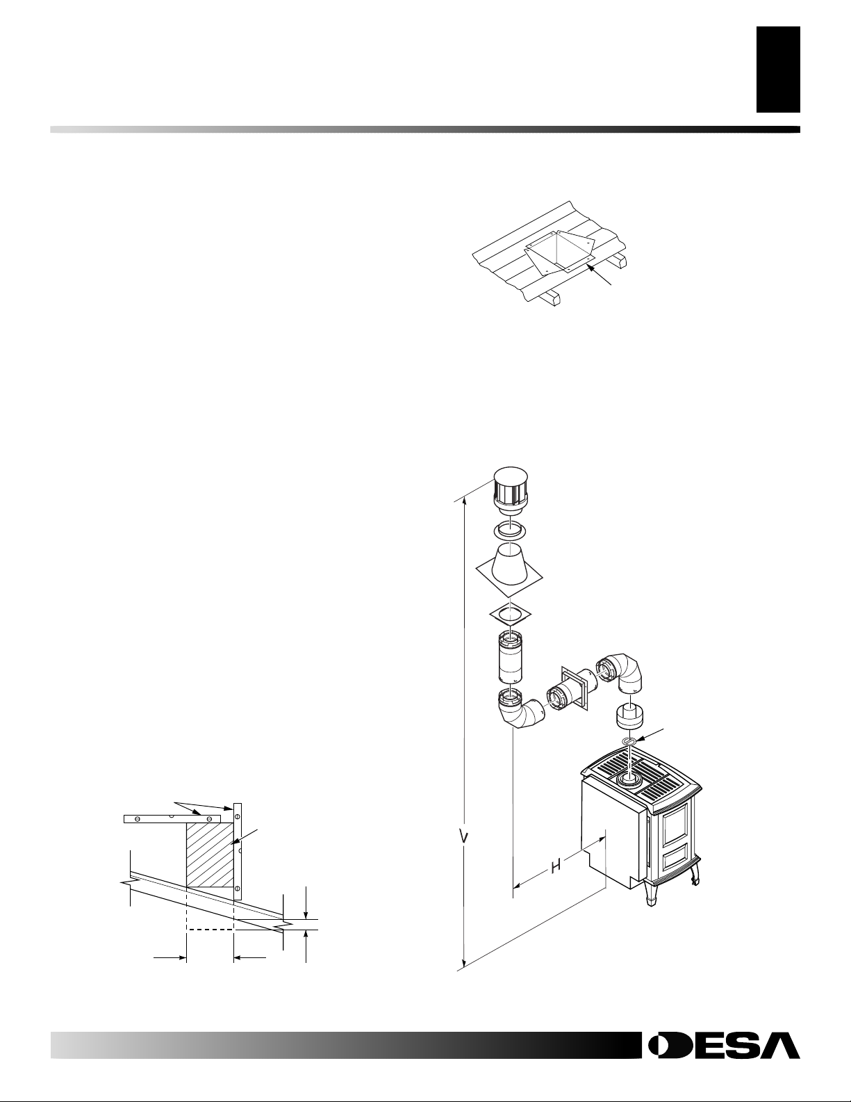
1. Remove shingles or other roof covering as necessary to cut the
rectangular hole for the support box. Mark the outline of the
cathedral ceiling support box on the roof sheathing using the
locating hole as a center point.
2. Cut the hole 1/8" larger than the support box outline (see
Figure 33).
3. Lower the support box through the hole in the roof until the
bottom of the box extends at least 2" below the ceiling (see
Figure 33). Align the support box vertically and horizontally
using a level. Temporarily tack the support box in place through
the inside walls and into the roof sheathing.
4. Using tin snips, cut the support box from the top corners down
to the roofline and fold the resulting flaps over the roof sheathing (see Figure 34). Apply a bead of nonhardening mastic around
the top edges of the support box to make a seal between the box
and the roof. Nail in place with roofing nails. Remove any combustible material that might be inside of the support box.
5. Complete the cathedral ceiling installation by following the same
procedures outlined in steps 2 through 7 for Flat Ceiling Instal-
lation, page 16
Level
Note
: You must increase vent height for
.
Cathedral Ceiling
Support Box
VENTING INSTALLATION
Installation for Vertical Termination (Cont.)
Nonhardening mastic under
all edges of support box
before nailing
Figure 34 - Installed Cathedral Ceiling Support Box
17
17
Vertical Termination Configurations
Figure 35 through 38 show four different configurations for vertical
termination. All connections must be sealed with high temperature
silicone sealant as specified in the second warning statement on
page 12.
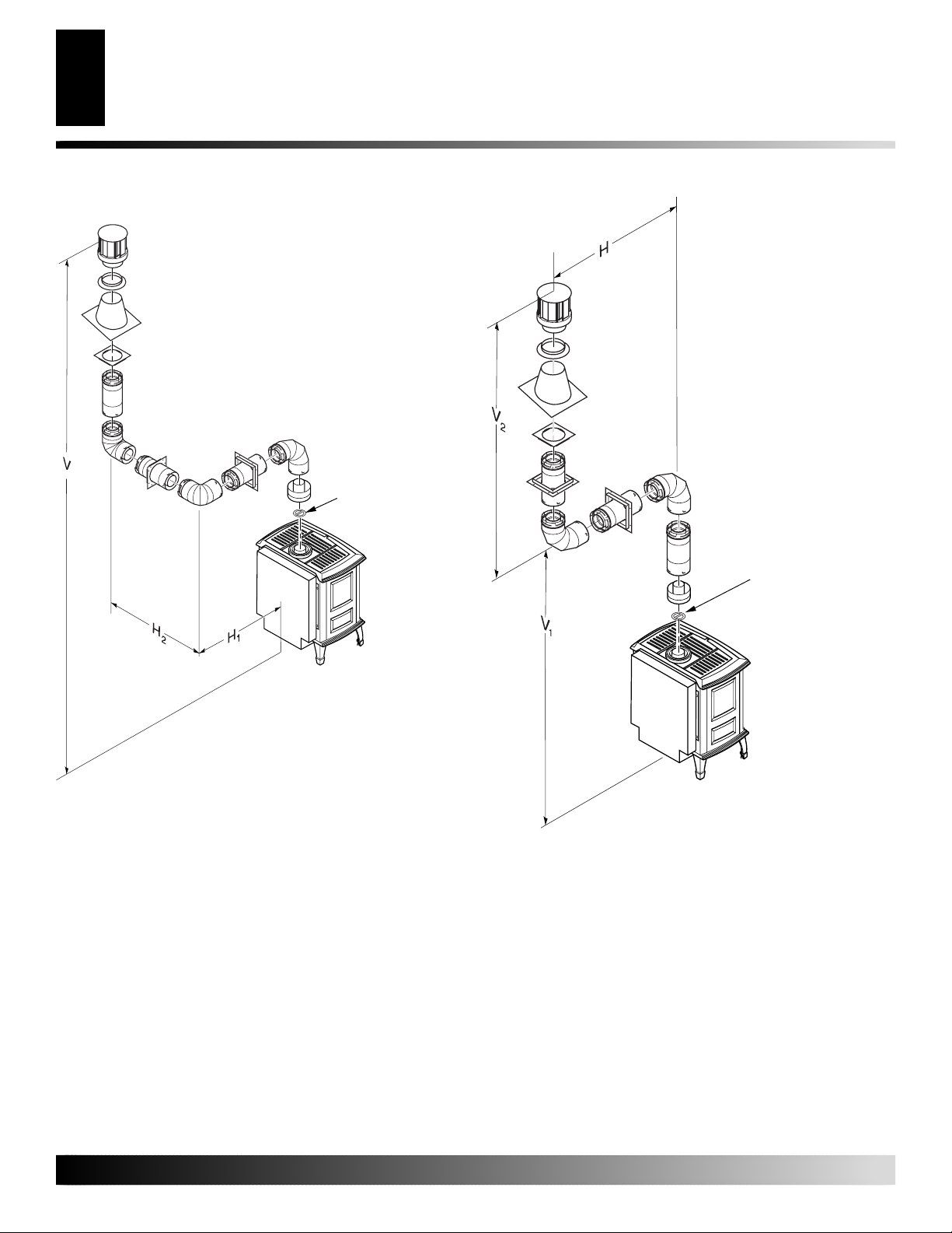
Venting with Two 90° Elbow
Vertical (V) Horizontal (H)
5' min. 2' max.
6' min. 4' max.
7' min. 6' max.
8' min. 8' max.
20' max. 8' max.
Note:
Install restrictor
into 4" collar of burner
system as shown.
2" minimum
below finished
ceiling
Cut hole 1/8" larger than support
box when projected onto roofline
Figure 33 - Cathedral Ceiling Support Box Installation
For more information, visit www.desatech.com
For more information, visit www.desatech.com
112126-01B
Figure 35 - Vertical Venting Configuration Using Two 90° Elbow
Page 18
18
VENTING INSTALLATION
Installation for Vertical Termination (Cont.)
VENTING INSTALLATION
Continued
Venting with Three 90° Elbows
Vertical (V) Horizontal (H1) +
Horizontal (H2)
5' min. 2' max.
6' min. 4' max.
7' min. 6' max.
8' min. 8' max.
20' max. 8' max.
Note:
Install
restrictor into 4"
collar of burner
system as shown.
Venting with Two
90° Elbows
Vertical (V1) Horizontal (H)
5' min. 6' max.
6' min. 12' max.
7' min. 18' max.
8' min. 20' max.
Note:
Vertical (V1) +
Vertical (V2) = 20' max.
Figure 36 - Vertical Venting Configuration Using Three 90
Elbows with Two Horizontal Runs
Note:
Install
restrictor into 4"
collar of burner
system as shown.
°
Figure 37 - Vertical Venting Configuration Using Two 90° Elbows
For more information, visit www.desatech.com
For more information, visit www.desatech.com
112126-01B
Page 19
VENTING INSTALLATION
Continued
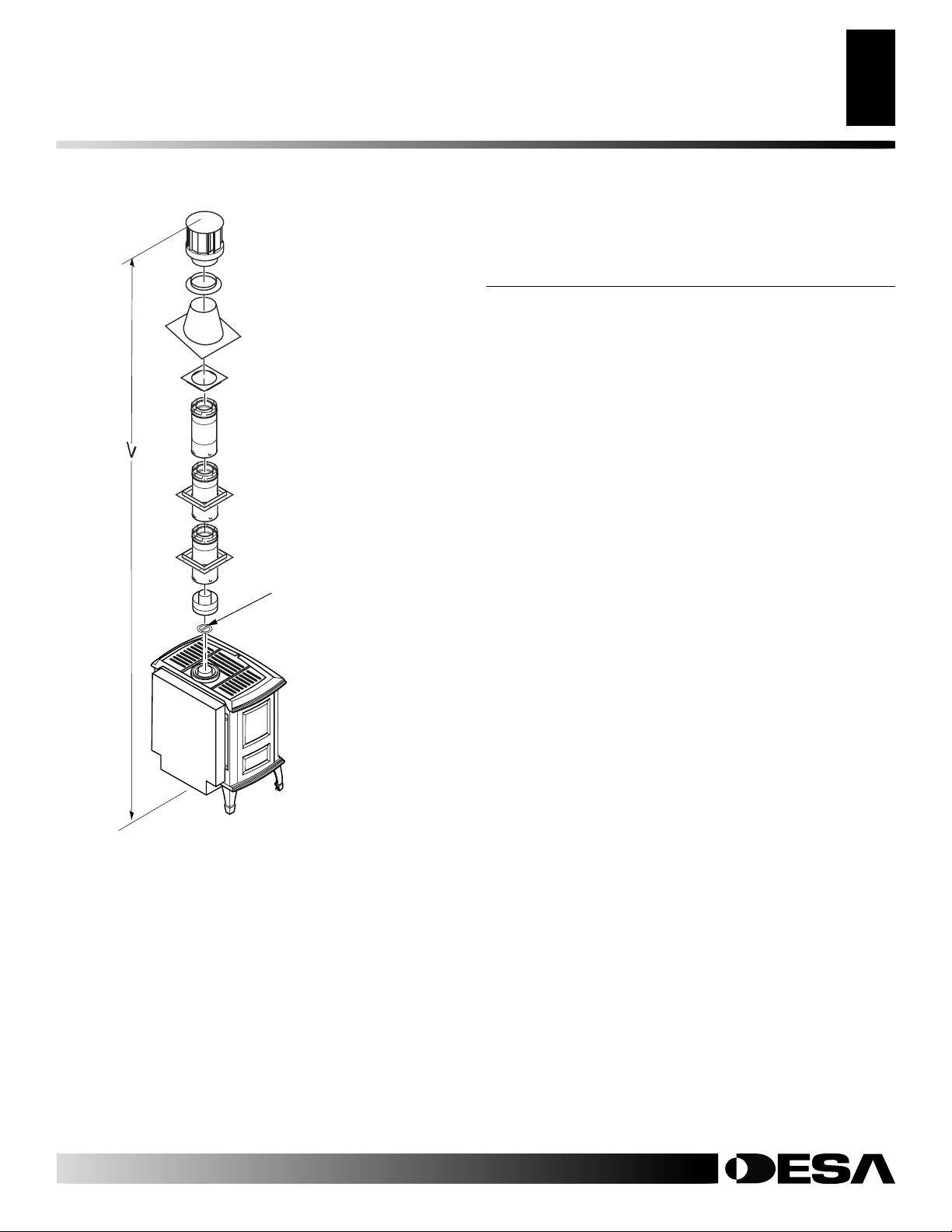
Vertical Venting
V = 40' max.
Note:
Install restrictor
into 4" collar of burner
system as shown.
Figure 38 - Vertical Venting Configuration With No
Horizontal Run
HIGH ALTITUDE INSTALLATION
Your cast iron stove and direct-vent burner system has been CSA
tested and approved for operation at altitudes in the USA from 02000 ft. and in Canada from 0-4500 ft.
When installing this stove at an elevation above 2000 feet (in the
USA), you may need to decrease the input rating by changing the
existing burner orifice to a smaller size. Reduce input 4% for each
1000 feet above sea level. Check with your local gas company for
proper orifice size identification and proper orifice for your location..
When installing this stove at an elevation above 4500 feet (in
Canada), check with local authorities.
For assistance with any high altitude installation contact DESA’s
Technical Service Department at 1-866-672-6040.
VENTING INSTALLATION
Installation for Vertical Termination (Cont.)
High Altitude Installation
Parts List for Venting Kits and Components
PARTS LISTS FOR VENTING KITS AND
COMPONENTS
Number Description
VKG-47-K Ground Floor Vent Kit, Black
Includes: Horizontal Square Termination, 90° Elbow, 7"12" Adjustable Coaxial Pipe, 6" Pipe Adaptor, 12" Coaxial
Pipe, Wall Firestop, Decorative Trim Plate and 18 Screws
VKB-47-K Basement Vent Kit
Includes: Horizontal Square Termination, 90° Elbow, 7"12" Adjustable Coaxial Pipe, 6" Pipe Adaptor, 4' Coaxial
Pipe, Wall Firestop, Decorative Trim Plate and 18 Screws
VKS-47-K Snorkel Vent Kit
Includes: 36" Snorkel Termination, 90° Elbow, 7"-12"
Adjustable Coaxial Pipe, 6" Pipe Adaptor, 4' Coaxial
Pipe, Wall Firestop, Decorative Trim Plate and 18 Screws
VKR-47-K Roof Vent Kit
Includes: Vertical High Wind Termination, Flue Restrictor, 7"-12" Adjustable Coaxial Pipe, 6" Pipe Adaptor, 12"
Coaxial Pipe, 4' Coaxial Pipe, Firestop Decorative Trim
Plate, Roof Flashing, Storm Collar and 18 Screws
P-47-12-K 12" Black Coaxial Pipe (1 pk)
P-47-24-K 24" Black Coaxial Pipe (1 pk)
P-47-48-K 48" Black Coaxial Pipe (1 pk)
PA47-712-K 7"-12" Black Coaxial Pipe (1 pk)
P-47-6-K 6" Black Coaxial Pipe (1 pk)
E47-90-K 90° Elbow (1 pk)
E47-45-K 45° Elbow (1 pk)
PA-47-6-K 6" Adaptor Collar, Black (1 pk)
WS-47 Wall Strap (1 pk)
SC-47 Storm Collar (1 pk)
VT-47 Vertical Round Termination (1 pk)
WF-47 Wall Firestop (1 pk)
VR-47 Vertical Restrictor (1 pk)
FP-47 Firestop Plate (1 pk)
HTS-47 Horizontal Square Termination (1 pk)
CS-47 Cathedral Ceiling Support Box (1 pk)
RF-47-6 Roof Flashing 0 to 6/12 Pitch (1 pk)
RF-47-12 Roof Flashing 6/12 to 12/12 Pitch (1 pk)
S-47 Vinyl Siding Standoff (1 pk)
TP-47 Trim Plate, Black (1 pk)
HT-47 Horizontal Round Termination (1 pk)
ST-47-14 14" Snorkel Termination (1 pk)
ST-47-36 36" Snorkel Termination (1 pk)
19
19
112126-01B
For more information, visit www.desatech.com
For more information, visit www.desatech.com
Page 20
20
STOVE AND DIRECT-VENT BURNER SYSTEM INSTALLATION
Check Gas Type
Installing Gas Piping to Stove/Burner System Location
STOVE AND DIRECT-VENT
BURNER SYSTEM
INSTALLATION
CHECK GAS TYPE
Use proper gas type for the burner system unit you are installing. If
you have conflicting gas types, do not install burner system. See
dealer where you purchased the stove and burner system for proper
burner system according to your gas type. Conversion kits are also
available for these models, see Accessories on page 38.
IMPORTANT:
Be sure to follow all installation instructions included with
conversion kit.
INSTALLING GAS PIPING TO STOVE/
BURNER SYSTEM LOCATION
WARNING: A qualified installer or service person
must connect burner system to gas supply. Follow all
local codes.
CAUTION: For propane/LP units, never connect
burner system directly to the propane/LP supply. This
burner system requires an external regulator (not
supplied). Install the external regulator between the
burner system and propane/LP supply.
If installing gas conversion kit, do so at this time.
CAUTION: Use only new, black iron or steel pipe.
Internally-tinned copper tubing may be used in certain areas. Check your local codes. Use pipe of 1/2"
diameter or greater to allow proper gas volume to
burner system. If pipe is too small, undue loss of
volume will occur.
Installation must include an equipment shutoff valve, union, and
plugged 1/8" NPT tap. Locate NPT tap within reach for test gauge hook
up. NPT tap must be upstream from burner system (see Figure 40).
IMPORTANT:
an accessible location. The main gas valve is for turning on and
shutting off the gas to the appliance.
Check your building codes for any special requirements for locating
equipment shutoff valve to stoves.
Install main gas valve (equipment shutoff valve) in
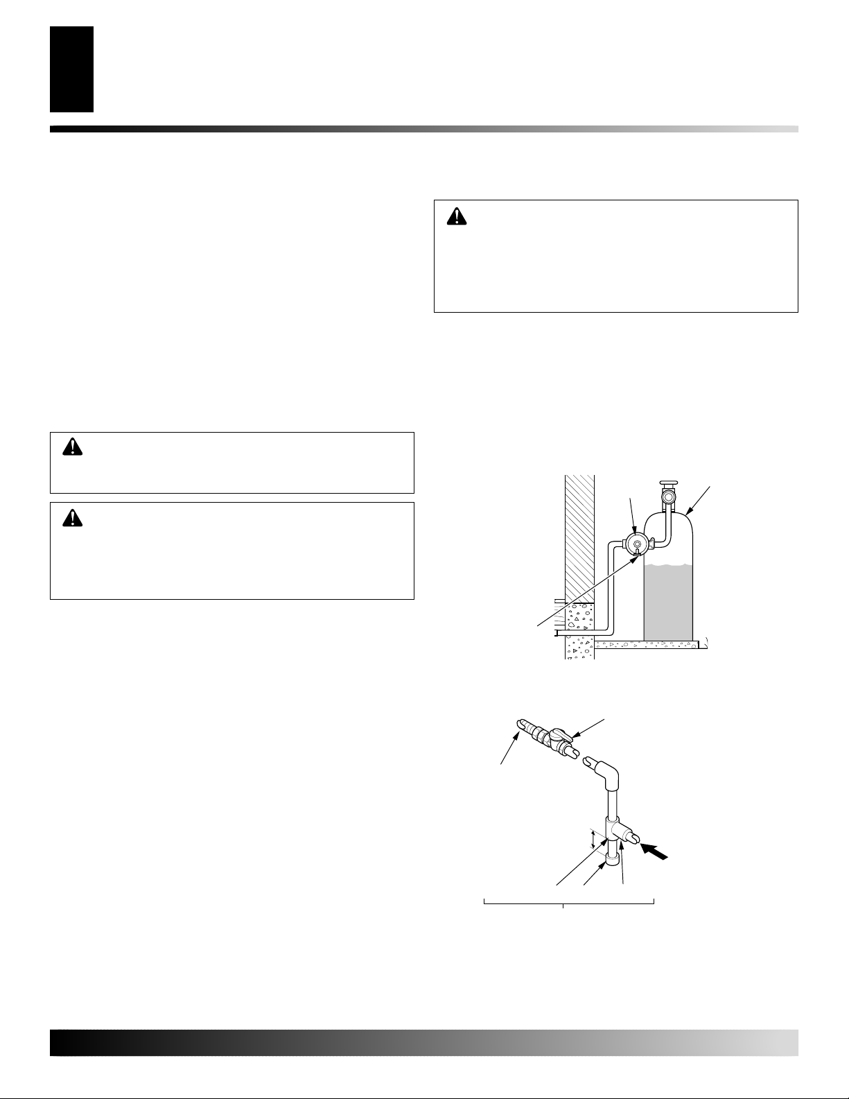
External
Regulator
Propane/LP
Supply Tank
Installation Items Needed
Before installing stove and burner system, make sure you have the
items listed below.
• external regulator (supplied by installer)
• piping (check local codes)
• sealant (resistant to propane/LP gas)
• equipment shutoff valve *
• test gauge connection *
• sediment trap
• tee joint
• pipe wrench
• approved flexible gas line with gas connector (if allowed by local codes) (not provided)
* A CSA design-certified equipment shutoff valve with 1/8" NPT tap
is an acceptable alternative to test gauge connection. Purchase the
CSA design-certified equipment shutoff valve from your dealer.
For propane/LP connections only, the installer must supply an
external regulator. The external regulator will reduce incoming gas
pressure. You must reduce incoming gas pressure to between 11 and
14 inches of water. If you do not reduce incoming gas pressure,
burner system regulator damage could occur. Install external regulator with the vent pointing down as shown in Figure 39. Pointing
the vent down protects it from freezing rain or sleet.
Vent Pointing
Down
Figure 39 - External Regulator with Vent Pointing Down
(Propane/LP Only)
CSA Design-Certified
Equipment Shutoff Valve with
1/8" NPT Tap*
Approved Flexible
Gas Line
3" Minimum
Pipe Nipple Cap Tee Joint
Sediment Trap/Drip Leg
Figure 40 - Gas Connection
* The CSA design-certified equipment shutoff valve may be supplied with the appliance or you can purchase it from your dealer.
Natural - From Gas
Meter (5" W.C. to
10.5" W.C. Pressure)
Propane/LP - From
External Regulator
(11" W.C. to 14" W.C.
Pressure)
For more information, visit www.desatech.com
For more information, visit www.desatech.com
112126-01B
Page 21
STOVE AND DIRECT-VENT BURNER SYSTEM INSTALLATION
Installing Gas Piping to Stove/Burner System Location (Cont.)
STOVE AND DIRECT-VENT
BURNER SYSTEM
INSTALLATION
Continued
Apply pipe joint sealant lightly to male NPT threads. This will
prevent excess sealant from going into pipe. Excess sealant in pipe
could result in clogged burner system valves.
WARNING: Use pipe joint sealant that is resistant
to liquid petroleum (LP) gas.
We recommend that you install a sediment trap/drip leg in supply
line as shown in Figure 40, page 20. Locate sediment trap/drip leg
where it is within reach for cleaning. Install in piping system
between fuel supply and burner system. Locate sediment trap/drip
leg where trapped matter is not likely to freeze. A sediment trap traps
moisture and contaminants. This keeps them from going into burner
system gas controls. If sediment trap/drip leg is not installed or is
installed wrong, burner system may not run properly.
CONNECTING STOVE/BURNER SYSTEM TO
GAS SUPPLY
Installation Items Needed
• 5/16" hex socket wrench or nut-driver
• sealant (resistant to propane/LP gas, not provided)
1. Open lower door panel.
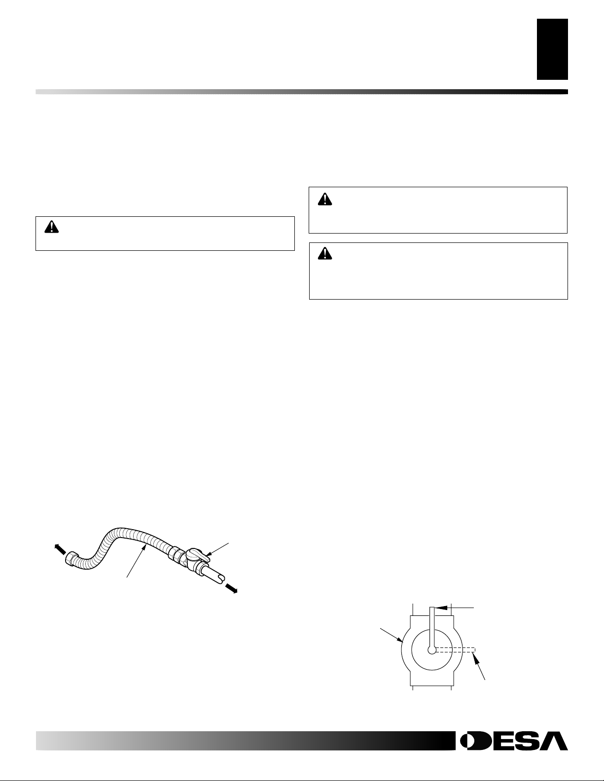
2. Route flexible gas line (provided by installer, see Figure 41)
from equipment shutoff valve to burner system. Route flexible gas supply line and attach to valve.
3. Check all gas connections for leaks. See Checking Gas
Connections, column 2.
To Flare Fitting on
Control Valve
Flexible Gas Line from
Equipment Shutoff Valve
Provided by Installer
Figure 41 - Flexible Gas Line
Equipment
Shutoff Valve
Natural - To
Gas Supply
Propane/LP To External
Regulator
21
21
Connecting Stove/Burner System to Gas Supply
Checking Gas Connections
CHECKING GAS CONNECTIONS
WARNING: Test all gas piping and connections
for leaks after installing or servicing. Correct all
leaks at once.
WARNING: Never use an open flame to check for
a leak. Apply noncorrosive leak detection solution to
all gas joints. Bubbles forming show a leak. Correct
all leaks at once.
Pressure Testing Gas Supply Piping System
Test Pressures In Excess Of 1/2 PSIG (3.5 kPa)
1. Disconnect appliance with its appliance main gas valve (control valve) and equipment shutoff valve from gas supply piping systems. Pressures in excess of 1/2 psig (3.5 kPa) will damage burner system gas regulator.
2. Cap off open end of gas pipe where equipment shutoff valve
was connected.
3. Pressurize supply piping system by either opening propane/LP
supply tank valve for propane/LP gas burner system or opening
main gas valve located on or near gas meter for natural gas burner
system, or using compressed air.
4. Check all joints of gas supply piping system. Apply noncorrosive leak detection solution to all gas joints. Bubbles forming
show a leak. Correct all leaks at once.
5. Reconnect burner system and equipment shutoff valve to gas
supply. Check reconnected fittings for leaks.
Test Pressures Equal To or Less Than 1/2 PSIG (3.5 kPa)
1. Close equipment shutoff valve (see Figure 42).
2. Pressurize supply piping system by either opening propane/LP
supply tank valve for propane/LP gas burner system or opening
main gas valve located on or near gas meter for natural gas burner
system, or using compressed air.
ON
Open
Equipment
Shutoff
Valve
POSITION
112126-01B
Figure 42 - Equipment Shutoff Valve
For more information, visit www.desatech.com
For more information, visit www.desatech.com
OFF
POSITION
Closed
Page 22
22
STOVE AND DIRECT-VENT BURNER SYSTEM INSTALLATION
Checking Gas Connection (Cont.)
Installing Optional Wall Mount Switch - GWMS2
STOVE AND DIRECT-VENT
BURNER SYSTEM
INSTALLATION
Continued
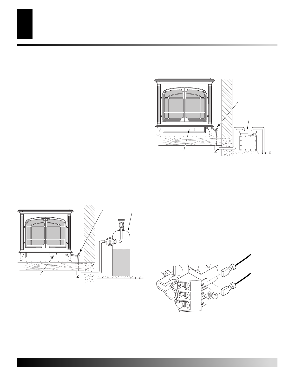
3. Check all joints from propane/LP supply tank or gas meter to
equipment shutoff valve (see Figure 43 for propane/LP or Figure
44 for natural). Apply noncorrosive leak test solution to all gas
joints. Bubbles forming show a leak. Correct all leaks at once.
Pressure Testing Burner System Gas Connections
1. Open equipment shutoff valve (see Figure 42, page 21).
2. Open propane/LP supply tank valve for propane/LP burner
system or main gas valve located on or near gas meter for natural gas burner system.
3. Make sure control knob of burner system is in the OFF position.
4. Check all joints from equipment shutoff valve to thermostat
gas valve (see Figure 43 for propane/LP or Figure 44 for natural). Apply noncorrosive leak detection solution to all gas joints.
Bubbles forming show a leak. Correct all leaks at once.
5. Light burner system (see Operating Stove with Burner System,
page 26). Check all other internal joints for leaks.
6. Turn off burner system (see To Turn Off Gas to Appliance,
page 26).
Equipment
Shutoff
Valve
Gas Valve
Propane/LP
Supply Tank
Equipment
Shutoff
Valve
Gas Meter
Gas Valve
Figure 44 - Checking Gas Joints for Natural Gas Burner System
(Oxford™ Model Shown)
INSTALLING OPTIONAL WALL MOUNT
SWITCH - GWMS2
1. Connect one terminal of 25 ft. wire for the wall switch to the
TPTH terminal on the valve. Connect remaining wire terminal
to the TH terminal on the valve. Make sure that the wire terminals are in the positions on the unit as pictured in Figure 45. If
wires are not connected as shown the switch will not work.
2. Route the 25 ft. wire through openings provided on the sides of
the burner system to a convenient location to mount your switch.
3. Connect one bare wire end to each of the terminals of the
GWMS2 wall switch.
4. Install the wall switch and cover in the wall.
To Control
Switch or
Optional
Accessory
Figure 43 - Checking Gas Joints for Propane/LP Gas Burner
System (Oxford™ Model Shown)
For more information, visit www.desatech.com
For more information, visit www.desatech.com
TPTH TP TH
Figure 45 - Control Valve Terminals
112126-01B
Page 23
STOVE AND DIRECT-VENT BURNER SYSTEM INSTALLATION
Installing Optional Wireless Hand-Held Remote Control Accessories - (C)GHRCB and (C)GHRCTB Series
STOVE AND DIRECT-VENT
BURNER SYSTEM
INSTALLATION
Continued
Installing Optional Wall Mounted Thermostat - GWMT1
23
23
INSTALLING OPTIONAL WALL MOUNTED
THERMOSTAT - GWMT1
WARNING: Installation must be done by a qualified
installer familiar with low voltage wiring procedures.
WARNING: Do not connect this thermostat to any
electrical source! Electrical shock and/or fire hazard
will occur.
1. Open lower door panel. The valve is attached to the underside
of the burner system assembly.
2. Disconnect from the valve the wires running from the ON/
OFF switch.
3. Connect one terminal of the wire for the wall thermostat to the
THTP terminal on the valve. Connect remaining wire terminal
to the TH terminal on the valve. Make sure that the wire terminals are in the positions on the unit as pictured in Figure 45,
page 22. If wires are not connected as shown the thermostat
will not work.
4. Route the wire to a convenient location to mount your thermostat (no outside wall).
ceed 25 feet in length. The thermostat should be mounted 54"
above the floor in a location where there is good air circulation. Avoid heat sources such as lamps, direct sunlight, fireplace, or heat and air conditioning ducts.
5. Gently remove the cover of the thermostat from the base. Grasp
the sides of the cover firmly and pull to separate from the base.
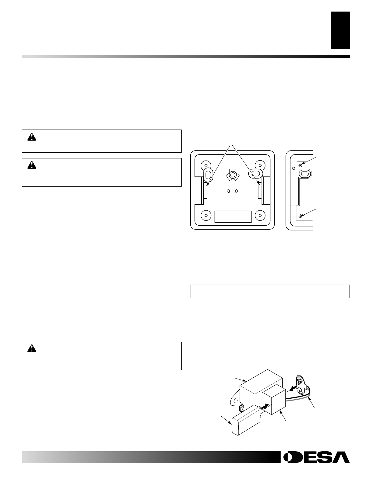
6. Feed the electrical wires through the rectangular slots (from
the back) on each side of the base (see Figure 46).
WARNING: Do not connect this thermostat to a
power source. Electrical shock and/or fire hazard
will occur.
IMPORTANT:
The wire must not ex-
11. Set the temperature adjustment to the desired setting. This thermostat has been electronically calibrated at the factory. No adjustment or leveling is necessary.
Feed wires through
rectangular slots
Terminal “W”
W
Terminal “R”
Figure 46 - Back View of
Thermostat Base
R
Figure 47 - Thermostat
Base Terminal “W” and “R”
INSTALLING OPTIONAL WIRELESS HANDHELD REMOTE CONTROL ACCESSORIES (C)GHRCB AND (C)GHRCTB SERIES
NOTICE: Use only alkaline batteries (not included).
Installing Remote Receiver and 9-volt Alkaline
Battery
1. Open bottom door on stove body.
2. Disconnect wires from THTP and TH on control valve that
lead to the switch (see Figure 45, page 22). Discard switch
plate, screws, and nuts.
3. Install 9-volt battery (not included) into receiver battery clip
and connect to terminals (see Figure 48).
7. Connect one bare wire end to each terminal (“W” and “R”) of
the thermostat base (see Figure 47).
8. Install the base to the wall with screws provided with thermostat.
9. Move the temperature adjustment back and forth to insure the
bimetal is free from restrictions.
10. Replace the cover onto the base. (Upon installation, the thermostat must be allowed to stabilize at room temperature for
a minimum of 30 minutes for proper operation.)
For more information, visit www.desatech.com
For more information, visit www.desatech.com
112126-01B
Receiver
9-Volt
Battery
Battery
Clip
Figure 48 - Installing Battery in Receiver
Terminal
Wires
Page 24
24
TPTH TP TH
STOVE AND DIRECT-VENT BURNER SYSTEM INSTALLATION
Installing Optional Wireless Hand-Held Remote Control Accessories - (C)GHRCB and (C)GHRCTB Series (Cont.)
Removing/Replacing Glass Door
STOVE AND DIRECT-VENT
BURNER SYSTEM
INSTALLATION
Continued
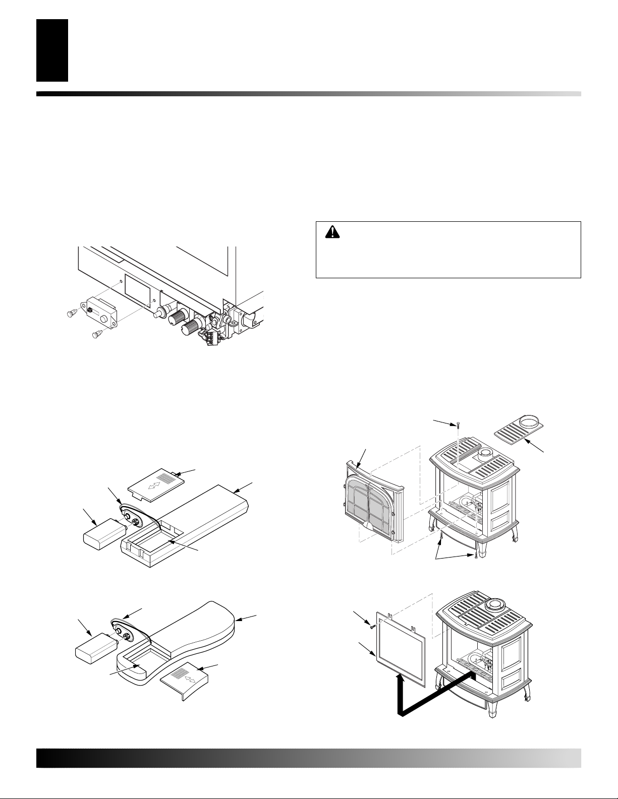
4. Place receiver into valve bracket and align holes (see Figure 49).
5. Use push-in fasteners included with receiver to secure to
bracket.
6. Connect the wires from the receiver to the valve at TH and
THTP (see Figure 45, page 22).
TPTH TP TH
Figure 49 - Installing Remote Receiver
Installing 9-Volt Alkaline Battery in Hand-Held
Remote Control Unit
1. Remove battery cover on back of remote control unit
2. Attach terminal wires to a 9-volt battery (not included). Place
battery into the battery housing.
3. Replace battery cover onto remote control unit.
9-Volt
Battery
Terminal
Wires
Battery
Cover
Remote
Control Unit
REMOVING/REPLACING GLASS DOOR
You must remove glass door to install logs, lava rock, and ember
material. To remove glass door, you must first remove the front
panel on stove body.
CAUTION: Do not operate this burner system with
a broken glass door panel or without the glass door
panel securely in place. For replacement part information see
1. If stove front panel is still installed, remove 2 bolts from bottom of stove and one from the top of stove to remove front panel
(see Figure 52). For the Oxford stove the middle grate will
need to be removed to remove the top bolt.
2. Remove the screws from the 2 tabs at the top of the glass door
while holding door securely keeping it from falling forward
(see Figure 53).
3. Grasp door by both sides and ease it upward off of the lower
bracket (see Figure 53).
4. To replace glass door, follow the above instructions in reverse.
Stove Front
Panel
Replacement Parts
Bolt
, page 33.
Middle
Grate
Battery
Housing
Figure 50 - Installing Battery in Hand-Held Remote Control Unit
(C)GHRCB Series
9-Volt
Battery
Battery Housing
Figure 51 - Installing Battery in Hand-Held Remote Control Unit
(C)GHRCTB Series
Terminal
Wires
Battery
Cover
For more information, visit www.desatech.com
For more information, visit www.desatech.com
Remote
Control
Unit
Bolt
Figure 52 - Removing Front Panel from Stove (Oxford™ Model
Shown)
Screw
Glass
Door
Figure 53 - Removing Glass Door from Burner System
112126-01B
Page 25
4
STOVE AND DIRECT-VENT BURNER SYSTEM INSTALLATION
STOVE AND DIRECT-VENT
BURNER SYSTEM
INSTALLATION
Continued
Installing Logs, Lava Rock and Glowing Embers
25
25
INSTALLING LOGS, LAVA ROCK AND
GLOWING EMBERS
WARNING: Failure to position the parts in accordance with these diagrams or failure to use only parts
specifically approved with this burner system may
result in property damage or personal injury.
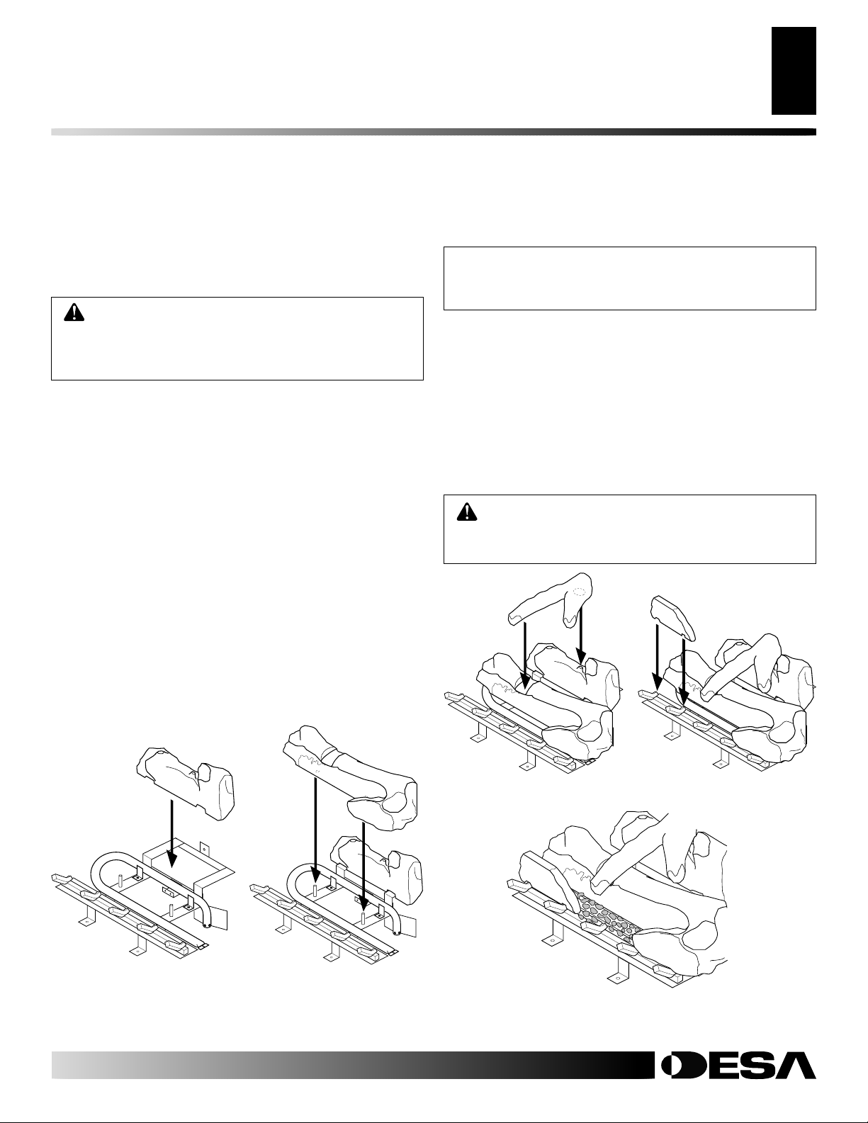
It is very important to install these logs exactly as instructed in
Figures 54 through 57. Do not modify logs. Only use logs supplied
with freestanding burner system. Do not use if any log(s) are broken
(see Replacement Parts, page 33).
1. Remove glass door. See Removing/Replacing Glass Door, page 24.
2. Place log #1 (back log) on top of grate. Make sure the notches
in the bottom of the log fit over the grate (see Figure 54).
2. Rest log #2 (large front log) on the pins on the front part of the grate
(see Figure 55).
3. Place log #3 (crossover log) onto the rear and front logs. Make
sure it is seated properly into the notch on the front log and
over the raised triangular portion of the rear log as shown in
Figure 56.
4. Place log #4 (small log) onto the front left part of the grate making
sure the notches fits over the prong of the grate. See Figure 57.
5. Lava rock may be placed along sides and front inside burner
system bottom. This may not be visible when you have replaced the front of the stove. It is not necessary to use all of
the lava rock provided.
NOTICE: Do not put lava rock on burner or under
burner. Placing lava rock on burner could cause
performance problems.
6. Pull ember material apart into pieces no larger than a dime.
Place these pieces loosely and sparingly directly onto the exposed section of the front burner and along the space between
the burner and grate prongs (see Figure 58). This will create
the glowing ember appearance as the flame touches the ember
material. Do not block air slots by using too much ember material in one area. It is not necessary to use all of the ember
material provided.
7. Replace the glass door and stove front. See Removing/Re-
placing Glass Door, page 24.
WARNING: The glass door must be securely in
place before running this burner system. Do not run
this burner system if glass is missing or broken.
3
Figure 54 - Installing Log
No. 1
For more information, visit www.desatech.com
For more information, visit www.desatech.com
112126-01B
1
Figure 55 - Installing Log No. 2
2
Figure 56 - Installing Log No. 3 Figure 57 - Installing Log No. 4
Figure 58 - Placing Ember Material on Burner
Page 26
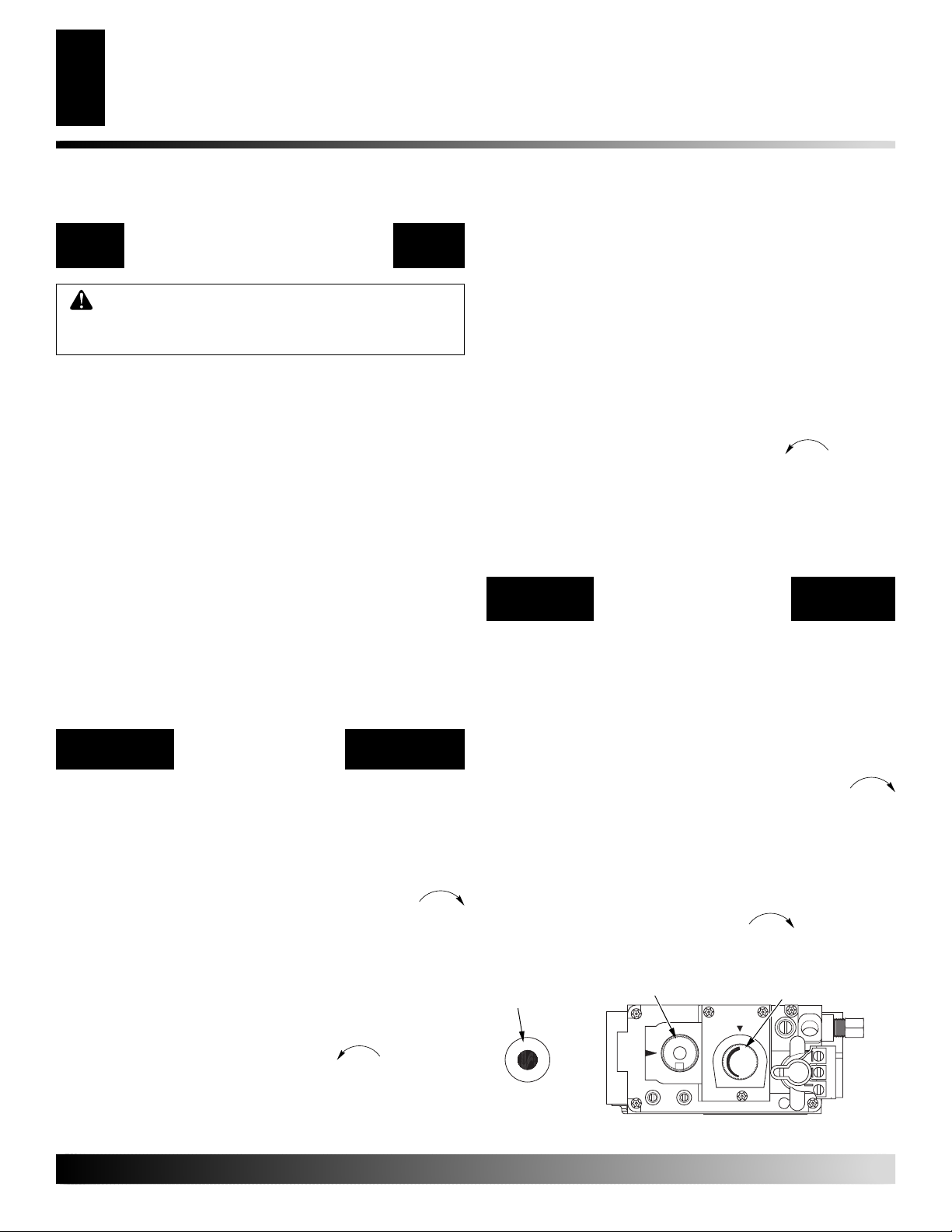
P
I
L
O
T
O
F
F
P
I
L
O
T
O
N
TPTH TP TH
HI
LO
IN
OUT
OPERATING STOVE AND BURNER SYSTEM
26
For Your Safety Read Before Opening
Lighting Instructions
To Turn Off Gas To Appliance
OPERATING STOVE WITH
BURNER SYSTEM
FOR YOUR SAFETY
READ BEFORE LIGHTING
WARNING: If you do not follow these instructions
exactly, a fire or explosion may result causing property damage, personal injury or loss of life.
A. This appliance has a pilot which must be lighted by hand.
When lighting the pilot, follow these instructions exactly.
B. BEFORE LIGHTING smell all around the appliance area
for gas. Be sure to smell next to the floor because some gas
is heavier than air and will settle on the floor.
WHAT TO DO IF YOU SMELL GAS
• Do not try to light any appliance.
• Do not touch any electric switch; do not use any phone in
your building.
• Immediately call your gas supplier from a neighbor’s
phone. Follow the gas supplier’s instructions.
C. Use only your hand to push in or turn the gas control knob.
Never use tools. If the knob will not push in or turn by hand,
don't try to repair it, call a qualified service technician. Force
or attempted repair may result in a fire or explosion.
D. Do not use this appliance if any part has been under water.
Immediately call a qualified service technician to inspect
the appliance and to replace any part of the control system
and any gas control which has been under water.
LIGHTING
INSTRUCTIONS
1. STOP! Read the safety information above.
2. Turn ON/OFF switch, located on side of rear cover, to
“OFF”.
3. Open lower door panel.
4. Turn off all electric power to the burner system.
5. Push in gas control knob slightly and turn clockwise
to “OFF”.
6. Wait five (5) minutes to clear out any gas. Then smell for
gas, including near the floor. If you smell gas, STOP! Follow “B” in the safety information above. If you don't smell
gas, go to the next step.
7. The pilot is located by the main burner and should not require accessing for lighting.
8. Turn gas control knob counterclockwise to “PILOT”.
9. Push in gas control knob all the way and hold. Immediately light the pilot by repeatedly depressing the piezo spark
ignitor until a flame appears. Continue to hold for about
one (1) minute after the pilot is lit. Release gas control knob
and it will pop back. Pilot should remain lit. If it goes out,
repeat steps 5 through 8.
• If gas control knob does not pop up when released, stop
and immediately call your service technician or gas
supplier.
• If the pilot will not stay lit after several tries, turn the
gas control knob to “OFF” and call your service technician or gas supplier.
10. Turn gas control knob counterclockwise to “ON”.
11. Turn on all electric power to the burner system.
12. Turn the ON/OFF switch to ON position.
13. This valve is equipped with a HI/LO feature. Set burner
system input as desired.
14. Close lower panel.
TO TURN OFF GAS
TO APPLIANCE
1. Turn ON/OFF switch, located on side of rear cover, to “OFF”.
2a. Open lower door panel.
2b. If Using Optional Hand-Held Remote: Set selector switch,
located on side of rear cover, in the OFF position to prevent draining battery.
3. Turn off all electrical power to the appliance if service is to
be performed.
4. Push in gas control knob slightly and turn clockwise
to “OFF”.
5. Close lower panel.
Shutting Off Burners Only (pilot stays lit)
You may shut off the burners and keep the pilot lit by doing one
of the following:
1. Turn gas control knob clockwise to the PILOT
position.
2. Set selector switch in the OFF position.
Piezo
Ignitor
Gas Control Knob
Variable
Control Knob
For more information, visit www.desatech.com
For more information, visit www.desatech.com
Figure 59 - Control Valve
112126-01B
Page 27
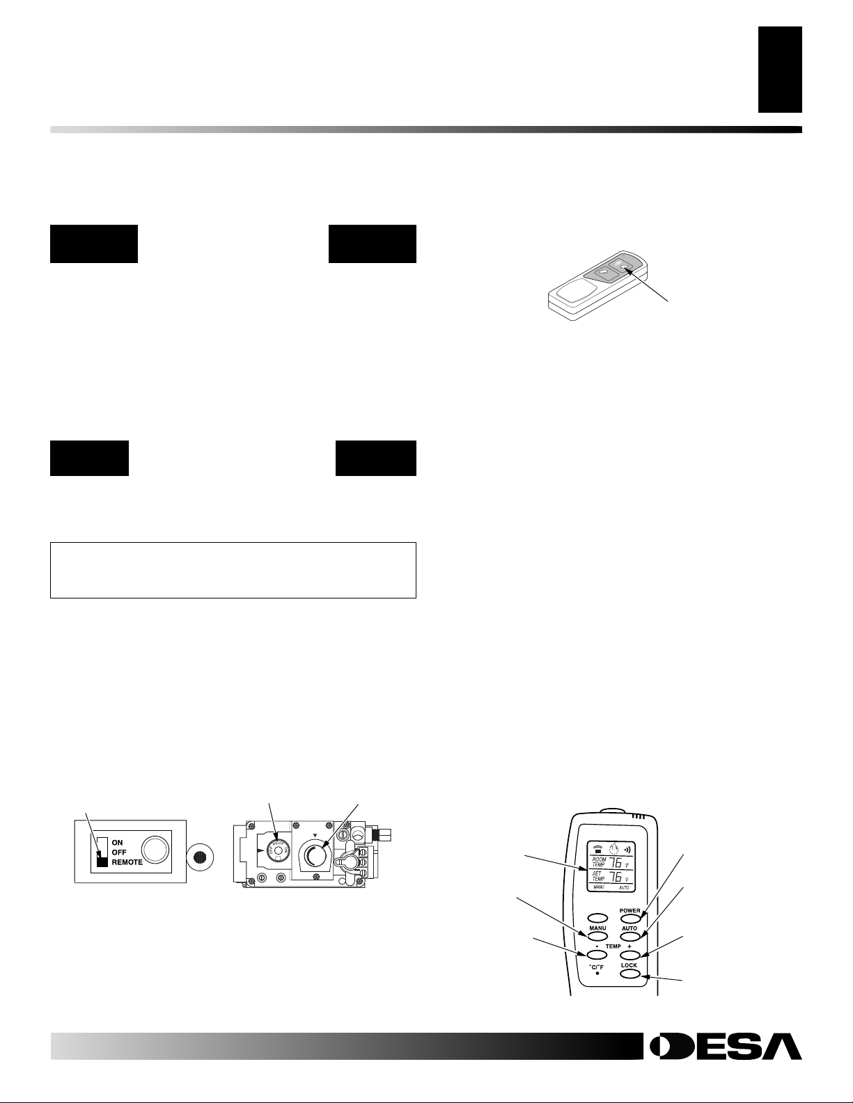
OPERATING STOVE AND BURNER SYSTEM
Manual Lighting Procedure
Optional Hand-Held Remote Operation
27
27
OPERATING STOVE WITH
BURNER SYSTEM
Continued
MANUAL LIGHTING
procedure
1. Remove glass door (see Removing/Replacing Glass Door,
page 24).
2. Follow steps 1 through 8 under Lighting Instructions, page 26.
3. Depress gas control knob and light pilot with match.
4. Keep gas control knob pressed in for 30 seconds after lighting
pilot. After 30 seconds, release gas control knob. Now follow
steps 10 through 14 under Lighting Instructions, page 26.
5. Replace glass door (see Removing/Replacing Glass Door,
page 24).
OPTIONAL HAND-HELD
REMOTE OPERATION
Note:
All remote control accessories must be purchased sepa-
rately (see Accessories, page 38). Follow instructions included
with the remote control.
NOTICE: You must light the pilot before using the
hand-held remote control unit. See
tions
on page 26.
1. After lighting, let pilot flame burn for about one minute.
Turn control knob to ON position. Adjust flame adjustment
knob anywhere between HI and LO. Slide the selector switch
to the REMOTE position (see Figure 60).
may light if hand-held remote was on when selector switch
was last turned off. You can now turn the burner on and off
with the hand-held remote control unit.
IMPORTANT:
Do not leave the selector switch in the REMOTE or ON position when the pilot is not lit. This will
drain the battery.
Selector Switch in Remote
Position (Optional Remote
Control)
Figure 60 - Setting the Selector Switch, Control Knob, and
Flame Adjustment Knob for Remote Operation
Gas Control Knob
in On Position
ON/OFF SERIES (MODELS GHRCB AND
CGHRCB)
Hold the control button on the hand-held remote until burner
turns on. Hold the control button again until burner turns off
(see Figure 61).
Lighting Instruc-
Note:
Variable
Control Knob
HI
LO
OUT
IN
The burner
To Lock press both buttons on hand-held remote control until
light stops flashing. Hand-held remote control is now locked. If
the fire is on it will be turned off automatically. In the locked
state, the light will not light up when any button is pressed.
To Unlock press both buttons together on hand-held remote control
until the light stops flashing. The hand-held remote is now unlocked.
Control Button
Turns Burners
On and Off
Figure 61 - On/Off Hand-Held Remote Control Unit (C)GHRCB
THERMOSTAT SERIES (MODELS GHRCTB
AND CGHRCTB)
The hand-held remote can be operated using either the manual mode
(MANU) or thermostatic mode (AUTO) (see Figure 62). To select
Fahrenheit/Centigrade mode display, carefully press the ˚C/˚F mode
button with the end of a paper clip or similar blunt object.
Manual Mode
1. Press the POWER and LOCK buttons together to turn on
the hand-held remote control.
2. Press the MANU button to turn on the fireplace.
3. Press the POWER and LOCK buttons together to turn
off the fireplace.
Auto (Thermostatic) Mode
1. Press the POWER and LOCK buttons together to turn on
the hand-held remote control.
2. Press AUTO button to select this mode.
3. Set the desired room temperature by pressing the TEMP
+ or - buttons.
4. Press the POWER and LOCK buttons together to turn
off the fireplace
Note:
Do not leave the hand-held remote in the AUTO mode
close to the fireplace. The radiant heat from the fireplace will
turn off the fireplace. Ideally, place the hand-held remote in the
center of the room facing towards the fireplace.
Note:
Do not hold the hand-held remote for a long time. Body
temperature will affect its operation in the AUTO mode.
Digital Display
Shows
Temperature and
Settings
Turns Burners
On or Off
Decreases Room
Temperature in
AUTO Mode
Figure 62 - Thermostat Hand-Held Remote Control Unit
(C)GHRCTB
Turns Hand-Held
Remote On or Off and
Allows You to Choose
the Manual Setting
Selects Auto Setting
Increases Room
Temperature in
AUTO Mode
Locks System to
Prevent Accidental
Ignition
112126-01B
For more information, visit www.desatech.com
For more information, visit www.desatech.com
Page 28
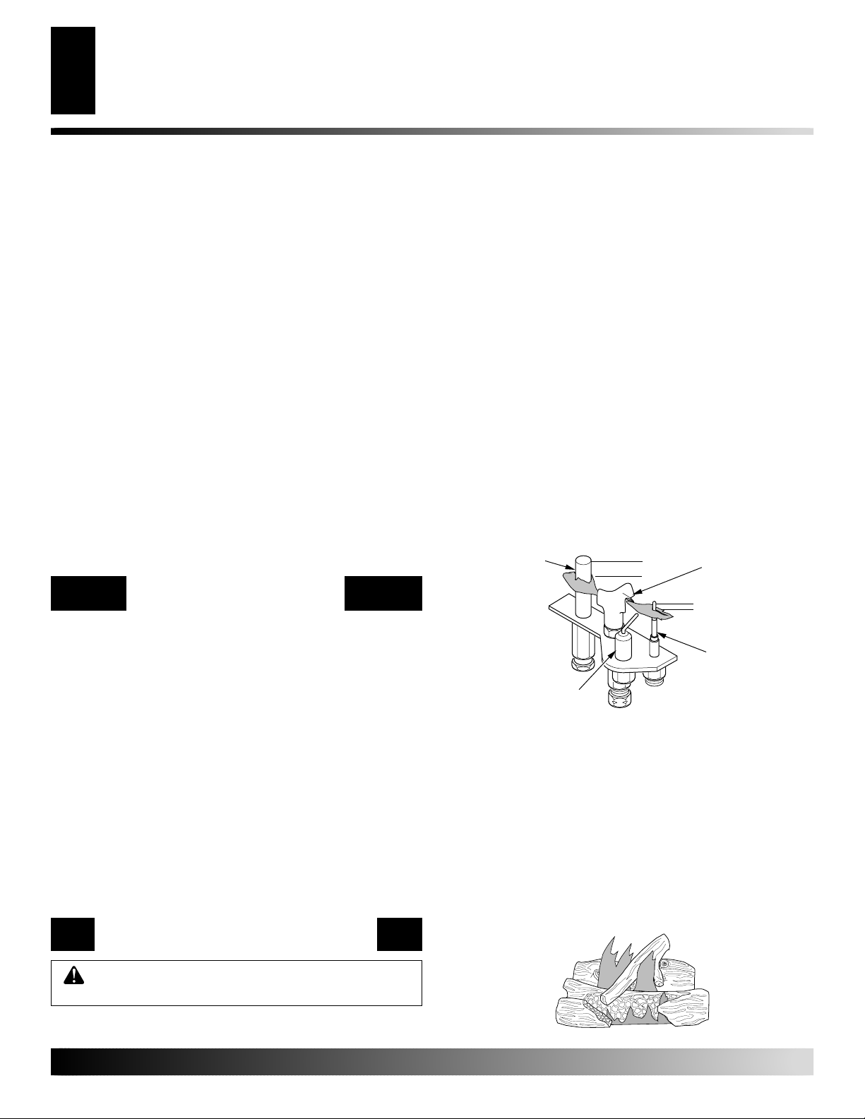
28
OPERATING STOVE AND BURNER SYSTEM
Optional Hand-Held Remote Operation (Cont.)
Operating Optional Blower Accessory
Operating Optional GWMT1 Wall Mounted Thermostat
INSPECTING BURNERS
Pilot Assembly
Burner Flame Pattern
OPERATING STOVE WITH
BURNER SYSTEM
Continued
Safety Features
When away from home for an extended period of time or as a child
safety feature to prevent accidental ignition of the fireplace, the
receiver ON/OFF/REMOTE switch should be in the OFF position.
Auto Shutoff Feature
1. If the average room temperature exceeds 82 degrees Fahrenheit (28 degrees Centigrade), the hand-held remote control will perform a safety override and shut the fireplace
off. This feature is not available in the MANU mode.
2. The receiver continuously receives signals from the handheld remote to control the room temperature. If the handheld remote is misplaced, obstructed, or for any reason cannot transmit to the receiver, the receiver will shut off the
fireplace after 8 minutes.
Key Pad Lock Feature
This feature allows the user to lock/unlock the keypad on the
hand-held remote in the MANU or AUTO mode to prevent
inadvertent operation (i.e. children operating the hand-held remote control, etc.). The keypad is locked in either on or off. Press
the POWER and LOCK buttons together to turn the unit on or off.
OPERATING OPTIONAL
BLOWER ACCESSORY
Blower controls are located on left side of rear cover (when
standing in front of stove).
The CDA3620TB thermostatically-controlled blower has an
ON setting and an OFF setting. The blower will only run when
the switch is in the ON position. In the OFF position, the blower
will not operate.
If you are using CDA3620TB blower with optional thermostat
(wall mount or remote control) for the burner system, your
burner system and blower will not turn on and off at the same
time. The burner system may run for several minutes before the
blower turns on. After the burner system modulates to the pilot
position, the blower will continue to run. The blower will shut off
after the burner system temperature decreases.
The blower helps distribute heated air from the burner system.
Periodically check the air passageways of the burner system
and remove any dust, dirt, or other obstructions that will hinder
the flow of air.
OPERATING OPTIONAL GWMT1
WALL MOUNTED THERMOSTAT
This thermostat has been electronically calibrated at the factory
and requires no adjustment or leveling.
Upon installation, the thermostat must be allowed to stabilize at room
temperature for a minimum of 30 minutes for proper operation.
To turn the burner system off, adjust thermostat to the lowest
setting and turn the gas control knob back to PILOT. The pilot
will remain lit.
IMPORTANT:
on the burner system to the OFF position.
To turn the pilot off, turn the gas control knob
INSPECTING BURNERS
Check pilot flame pattern and burner flame patterns often.
PILOT ASSEMBLY
The pilot assembly is factory preset for the proper flame height.
Alterations may have occurred during shipping and handling. Call
a qualified service person to readjust the pilot if necessary.
The height of the thermopile must be 3/8" to 1/2" above the pilot
flame as shown in Figure 63. The thermocouple must be at a height
of about 1/8" above the pilot flame. The flame from the pilot burner
must extend beyond both the thermocouple and thermopile.
If your pilot assembly does not meet these requirements:
• turn burner system off (see To Turn Off Gas to Appliance, page 26)
• see Troubleshooting, page 30
Thermopile
Piezo Ignitor
Figure 63 - Pilot Assembly
3/8" to 1/2"
BURNER FLAME PATTERN
Burner flames will be steady; not lifting or floating. Flame patterns
will be different from unit to unit and will vary depending on
installation type and weather conditions.
If the vent configuration is installed incorrectly, the flames will lift
or “ghost”. This can be dangerous. Inspect the flames after installation to ensure proper installation and performance.
Figure 64 shows a typical flame pattern. If burner flame pattern differs
from that described:
• turn burner system off (see To Turn Off Gas to Appliance, page 26)
• see Troubleshooting, page 30
Pilot Burner
1/8"
Thermocouple
WARNING: Do not connect the thermostat to a power
source. Electrical shock and/or a fire hazard will occur.
Light the
page 26. Set wall thermostat to desired temperature.
burner system
as instructed in Lighting Instructions on
For more information, visit www.desatech.com
For more information, visit www.desatech.com
Figure 64 - Typical Flame Pattern
112126-01B
Page 29
CLEANING AND MAINTENANCE
CLEANING AND MAINTENANCE
Glass Door
Pilot and Burners
Logs
Venting System
29
29
WARNING: Turn off burner system and let cool
before cleaning.
CAUTION: You must keep control areas, burners,
and circulating air passageways of burner system
and stove clean. Inspect these areas of burner system and stove before each use. Have burner system
and stove inspected yearly by a qualified service
person. Burner system and stove may need more
frequent cleaning due to excessive lint from carpeting, bedding material, pet hair, etc.
GLASS DOOR
WARNING: Handle glass door panel with care.
Do not strike, slam, or otherwise abuse glass. Do not
operate burner system with the glass door removed,
cracked, or broken.
WARNING: Do not use abrasive cleaners as this
may damage glass. Use a nonabrasive household
glass cleaner to clean glass. Do not clean glass
when hot.
Glass must be cleaned periodically. During start-up it is normal for
condensation to form on the inside of the glass causing lint, dust, and
other airborne particles to cling to the glass surface. During initial
startup a slight film may form on the glass due to paint curing. The
glass should be cleaned several times with a non-ammonia, nonabrasive household cleaner and warm water after the first two weeks
of operation. Thereafter, clean the glass two or three times during
each heating season, depending on the usage and circumstances
present. Refer to Removing/Replacing Glass Door on page 24 of this
manual when removing glass door for cleaning.
WARNING: Only parts supplied by the manufacturer should be used when replacing broken or
damaged glass door panel (see
page 33). This glass door panel is a complete unit.
No substitute materials may be used.
CAUTION: Wear gloves and safety glasses while
handling or removing broken glass. Do not remove if
glass is hot. Keep children and pets away from glass.
Replacement Parts
,
CAUTION: Do not vacuum if pieces are hot.
Use only the ceramic glass door replacement intended for this
burner system (see Replacement Parts, page 33 for detail on
ordering). No substitutions may be made. See Removing/Replacing
Glass Door, page 24 for instructions for replacing glass door.
WARNING: Do not operate burner system with the
glass door removed, cracked, or broken.
PILOT AND BURNERS
• Remove ember material before cleaning burners and replace
when cleaning is complete.
• Burner and controls should be cleaned with compressed air to
remove dust, dirt, or lint.
• Use a vacuum cleaner or small, soft bristled brush to remove
excess dust, dirt, or lint.
LOGS
• If you remove logs for cleaning, refer to Installing Logs, Lava
Rock, and Glowing Embers, page 25, to properly replace logs.
• Use a vacuum cleaner to remove any carbon buildup on logs.
• Replace log(s) if broken. See Replacement Parts on page 33.
• Replace ember material periodically as needed. See Replacement
Parts on page 33.
VENTING SYSTEM
Conduct annual inspection of the venting system following these
guidelines:
1. Check areas of venting system that are exposed to the
weather for corrosion (rust spots or streaks and, in extreme
cases, holes). Have these items replaced immediately by a
qualified service person.
2. Remove the vent cap and shine a flashlight into the vent.
Remove any foreign material.
3. Check for evidence of excessive condensation. Continuous
condensation can cause corrosion of caps, pipes, and fittings
and can be caused by having excessive lateral runs, too many
elbows, or exterior portions of the system being exposed to
cold weather.
4. Inspect joints to verify that no pipe section or fitting has been
disturbed and loosened. Check mechanical supports such as
wall straps for rigidity.
If glass has been broken, carefully remove glass door (see Remov-
ing/Replacing Glass Door, page 24). Vacuum all glass pieces with
a shop vac.
For more information, visit www.desatech.com
For more information, visit www.desatech.com
112126-01B
Page 30
30
TROUBLESHOOTING
TROUBLESHOOTING
Note:
For additional help, visit DESA’s
technical service web site at
www.desatech.com.
Note:
All troubleshooting items are listed in
order of operation.
WARNING: Turn off burner system
and let cool before servicing. Only a
qualified service person should service and repair burner system or stove.
CAUTION: Never use a
wire, needle, or similar object to clean pilot. This can
damage pilot unit.
OBSERVED PROBLEM
When ignitor button is pressed, there is no
spark at pilot
When ignitor button is pressed, there is
spark at pilot but no ignition
Pilot lights but flame goes out when control
knob is released
POSSIBLE CAUSE
1. Ignitor electrode not connected to ignitor cable
2. Ignitor cable pinched or wet
3. Piezo ignitor nut is loose
4. Broken ignitor cable
5. Bad piezo ignitor
6. Ignitor electrode broken
7. Ignitor electrode positioned wrong
1. Gas supply turned off or equipment
shutoff valve closed
2. Gas control knob not in PILOT position
3. Gas control knob not pressed in while
in PILOT position
4. Air in gas lines when installed
5. Depleted gas supply (propane/LP only)
6. Pilot is clogged
7. Gas regulator setting is not correct
1. Gas control knob not fully pressed in
2. Gas control knob not pressed in long
enough
3. Equipment shutoff valve not fully open
4. Pilot flame not touching thermocouple,
which allows thermocouple to cool,
causing pilot flame to go out. This problem could be caused by one or both of
the following:
A) Low gas pressure
B) Dirty or partially clogged pilot
5. Thermocouple connection loose at control valve
6. Thermocouple damaged
7. Control valve damaged
REMEDY
1. Reconnect ignitor cable
2. Free ignitor cable if pinched by any
metal or tubing. Keep ignitor cable dry
3. Tighten nut holding piezo ignitor. Nut
is located behind the mounting bracket
4. Replace ignitor cable
5. Replace piezo ignitor
6. Replace pilot assembly
7. Replace pilot assembly
1. Turn on gas supply or open equipment
shutoff valve
2. Turn gas control knob to PILOT position
3. Press in gas control knob while in PILOT
position
4. Continue holding down gas control
knob. Repeat igniting operation until air
is removed
5. Contact local propane/LP gas company
6. Clean pilot (see Cleaning and Mainte-
nance, page 29) or replace pilot assembly
7. Replace gas control
1. Press in gas control knob fully
2. After pilot lights, keep gas control knob
pressed in 30 seconds
3. Fully open equipment shutoff valve
4. A) Contact local gas company
B) Clean pilot (see Cleaning and
Maintenance, page 29) or replace pilot
assembly
5. Hand tighten until snug, then tighten
1/4 turn more
6. Replace pilot assembly
7. Replace control valve
For more information, visit www.desatech.com
For more information, visit www.desatech.com
112126-01B
Page 31

TROUBLESHOOTING
Continued
TROUBLESHOOTING
31
31
OBSERVED PROBLEM
Burner does not light after pilot is lit
Delayed ignition burner
Burner backfiring during combustion
Slight smoke or odor during initial operation
Burner system produces a whistling noise
when burner is lit
POSSIBLE CAUSE
1. Burner orifice clogged
2. Inlet gas pressure is too low
3. Thermopile leads disconnected or improperly connected
4. Thermopile is defective
5. Gas valve is defective
1. Manifold pressure is too low
2. Burner porting or orifice clogged
1. Burner orifice is clogged or damaged
2. Damaged burner
3. Gas regulator defective
1. Residues from manufacturing processes
and logs curing
1. Turning gas control knob to HI position
when burner is cold
2. Air in gas line
3. Dirty or partially clogged burner orifice
REMEDY
1. Clean burner (see Cleaning and
Maintenance, page 29) or replace burner
orifice
2. Contact local propane/LP or natural gas
company
3. Reconnect leads (see Wiring Diagram,
page 33)
4. Replace thermopile
5. Replace gas valve
1. Contact local propane/LP or natural gas
company
2. Clean burner (see Cleaning and Main-
tenance, page 29) or replace burner orifice
1. Clean burner (see Cleaning and
Maintenance, page 29) or replace burner
orifice
2. Replace damaged burner
3. Replace gas control
1. Problem will stop after a few hours of
operation
1. Turn gas control knob to LO position and
let warm up for a minute
2. Operate burner until air is removed from
line. Have gas line checked by local propane/LP or natural gas company
3. Clean burner (see Cleaning and
Maintenance, page 29) or replace burner
orifice
Glass soots
Burner system produces a clicking/ticking
noise just after burners are lit or shut off
Remote does not function
For more information, visit www.desatech.com
For more information, visit www.desatech.com
112126-01B
1. Flame impingement on logs
2. Debris around burner air mixer
3. Improper vent configuration
1. Metal expanding while heating or contracting while cooling
1. Battery is not installed or battery power
is low
1. Adjust the log set so that the flame does
not excessively impinge on it
2. Inspect the opening at the base of the
burner to see that it is NOT packed with
any type of material
3. Follow venting configuration instructions
in owner’s manual
1. This is common. If noise is excessive,
contact qualified service person
1. Replace 9-volt batteries in receiver and
remote control
Page 32
32
TROUBLESHOOTING
TROUBLESHOOTING
Continued
WARNING: If you smell gas
• Shut off gas supply.
• Do not try to light any appliance.
• Do not touch any electrical switch; do not use any phone in your building.
• Immediately call your gas supplier from a neighbor’s phone. Follow the gas
supplier’s instructions.
• If you cannot reach your gas supplier, call the fire department.
IMPORTANT:
supplies, paint, paint remover, cigarette smoke, cements and glues, new carpet or textiles, etc., create
fumes. These fumes may mix with combustion air and create odors. These odors will disappear over time.
Operating burner system where impurities in air exist may create odors. Cleaning
OBSERVED PROBLEM
Burner system produces unwanted odors
Burner system shuts off in use
Gas odor even when control knob is in OFF
position
POSSIBLE CAUSE
1. Gas leak. See Warning statement
above
1. High or gusting winds
2. Low line pressure
3. Pilot is partially clogged
4. Inner vent pipe leaking exhaust gasses
into system
5. Glass too loose and air tight gasket leaks
in corners after usage
6. Bad thermopile or thermocouple
7. Improper vent cap installation
1. Gas leak. See Warning statement
above
2. Control valve defective
REMEDY
1. Locate and correct all leaks (see Checking Gas Connections, page 21)
1. Burner system has been tested for up to
40mph winds. However, extreme conditions may occur. See Lighting Instruc-
tions on page 26
2. Contact local propane/LP or natural gas
company
3. Clean pilot (see Cleaning and Mainte-
nance, page 29)
4. Locate and correct all leaks in venting
pipe
5. Tighten glass door
6. Replace faulty component
7. Check for proper installation and freedom from debris or blockage
1. Locate and correct all leaks (see Check-
ing Gas Connections, page 21)
2. Replace control valve
Gas odor during combustion
Dark residue on logs or inside of burner
system
For more information, visit www.desatech.com
For more information, visit www.desatech.com
1. Gas leak. See Warning statement
above
1. Improper log placement
2. Air holes at burner inlet blocked
3. Burner flame holes blocked
4. Improper vent configuration
1. Locate and correct all leaks (see Check-
ing Gas Connections, page 21)
1. Properly locate logs (see Installing Logs,
Lava Rock, and Glowing Embers, page 25)
2. Clean out air holes at burner inlets. Periodically repeat as needed
3. Remove blockage
4. Follow vent configuration instructions
in owner’s manual
112126-01B
Page 33
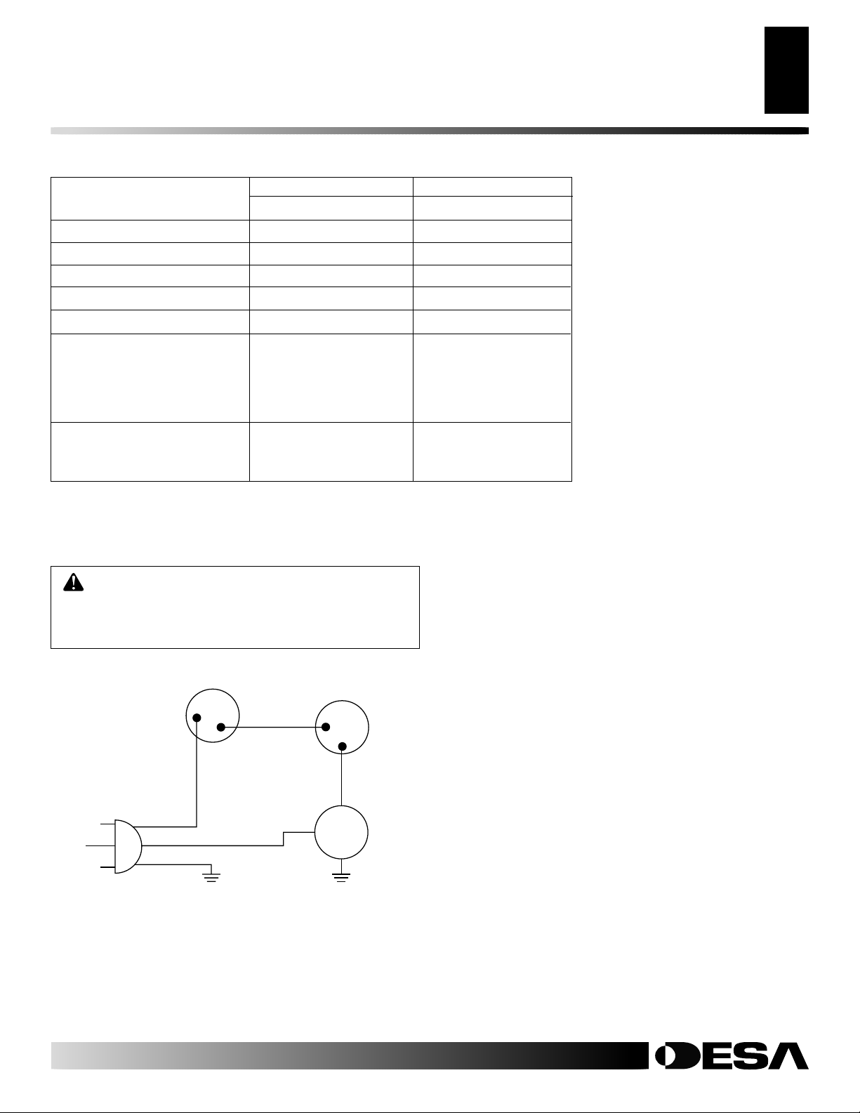
SPECIFICATIONS
SDVBND SDVBPD
21,000-30,000 Btu/h 20,000-28,000 Btu/h
Gas Type Natural Propane/LP
Ignition Piezo Piezo
Manifold Pressure 3.5" w.c. 10.0" w.c.
Minimum Inlet Supply Pressure 5.0" w.c. 11.0" w.c.
Thermal Efficiency 70% 70%
Dimension, Inches/mm (HxWxD)
Stove and Burner System* 27" x 21 1/2" x 18" 27" x 21 1/2" x 18"
68.6 x 54.6 x 45.7 cm 68.6 x 54.6 x 45.7 cm
Carton 23 3/4" x 33 1/2" x 23 1/2" 23 3/4" x 33 1/2" x 23 1/2"
60.3 x 85.1 x 59.7 cm 60.3 x 85.1 x 59.7 cm
Weight, lbs/kg
Burner System 70 lbs/31.8 kg 70 lbs/31.8 kg
Shipping 75 lbs/34 kg 75 lbs/34 kg
SPECIFICATIONS
WIRING DIAGRAM
REPLACEMENT PARTS
33
33
* When installed in a model SCIVF/PSCIVF series cast iron stove body.
WIRING DIAGRAM
REPLACEMENT PARTS
Note:
CAUTION: Label all wires prior to disconnection
when servicing controls. Wiring errors can cause
improper and dangerous operation. Verify proper
operation after servicing.
Variable
Fan Switch
1
Off
110/115
V.A.C.
Figure 65 - Blower Wiring Diagram for Thermostat-Controlled
Models
Black
White
Green
2
Black
On
Fan Switch
(N.O.)
Blue
Blower
Motor
warranty coverage for parts replaced under warranty.
PARTS UNDER WARRANTY
Contact authorized dealers of this product. If they can not supply
original replacement part(s), call DESA’s Technical Service Department at 1-866-672-6040.
When calling DESA, have ready
• your name
• your address
• model and serial numbers of your burner system and stove
• how burner system or stove was malfunctioning
• type of gas used (propane/LP or natural gas)
• purchase date
Usually, we will ask you to return the part to the factory.
PARTS NOT UNDER WARRANTY
Contact authorized dealers of this product. If they can not supply
original replacement part(s), call DESA at 1-866-672-6040 for
referral information.
When calling DESA, have ready
• model number of your burner system and stove
• the replacement part number
Use only original replacement parts. This will protect your
112126-01B
For more information, visit www.desatech.com
For more information, visit www.desatech.com
Page 34
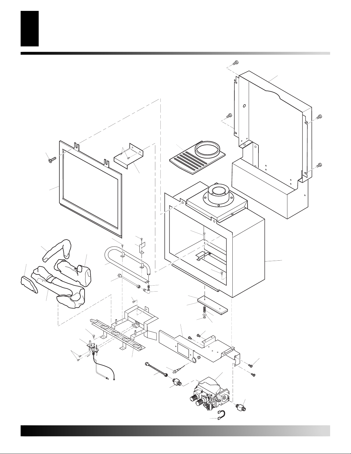
34
TPTH TP TH
ILLUSTRATED PARTS BREAKDOWN
Models SDVBND and SDVBPD
ILLUSTRATED PARTS
BREAKDOWN
MODELS
SDVBND
SDVBPD
3
26-4
26-3
26-2
23
4
5
4
4
25
4
6
2
26-1
19
20
21
18
12
1
4
9
8
28
10
11
15
22
TPTH TP TH
7
13
14
4
16
27
24
For more information, visit www.desatech.com
For more information, visit www.desatech.com
17
23
22
28
112126-01B
Page 35
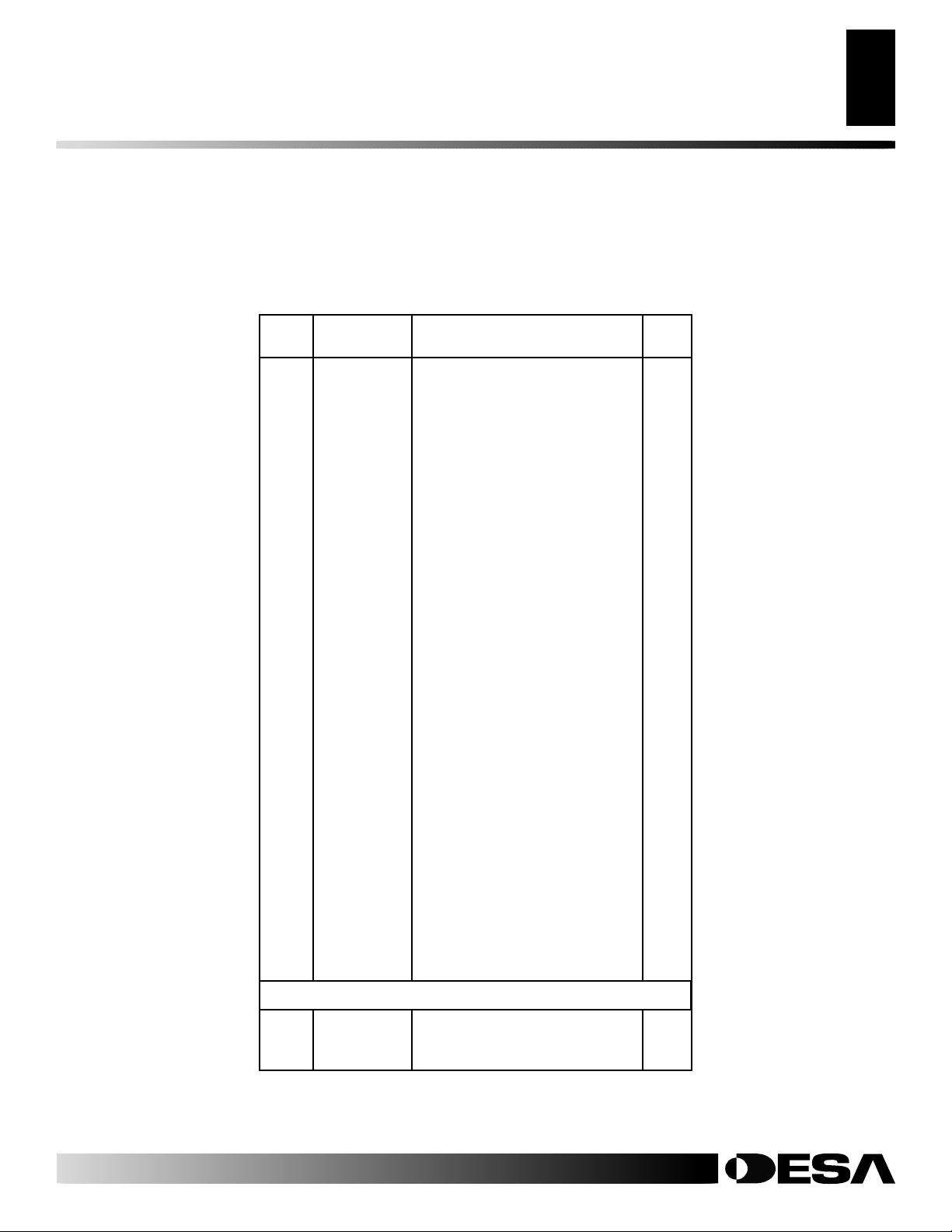
PARTS LIST
MODELS
SDVBND, SDVBPD
This list contains replaceable parts used in your burner system.
When ordering parts, follow the instructions listed under Replace-
ment Parts on page 33 of this manual.
KEY PART
NO. NUMBER DESCRIPTION QTY.
Models SDVBND and SDVBPD
PARTS LIST
35
35
1
2 105795-01 Glass Door Assembly 1
3
4 M11084-46 Screw, Hex 19
5 107191-01 Baffle 1
6 M12461-73 Screw 2
7 101480-12 Wire Assembly 1
8 104491-01 Relief Cover 1
9 104518-01 Relief Cover Gasket 1
10 104527-01 Relief Spring 2
11 104528-01 Relief Washer 2
12 H5C4-20B Hex Head Cap Screw 2
13 NTC-4C Locknut 2
14 105468-02CK Valve Bracket 1
15 104496-01 Valve, Natural 1
16 105486-01 Pilot Assembly, Natural 1
17 102445-01 Ignitor, Piezo 1
18 107014-01 Center Cast Stove Top Grate 1
19 106036-01 Burner, Natural 1
20 104506-16 Orifice, Natural 1
21 104507-01 Brass Elbow 1
22 097809-03 Brass Fitting 2
23 101628-04 Flex Tubing 2
24 106794-01CK Grate Assembly 1
25 105325-01 Air Deflector 1
26 105491-01 Log Set 1
26-1 105774-01 Rear Log 1
26-2 105774-02 Log 1
26-3 105774-03 Crossover Log 1
26-4 105774-04 Log Piece 1
27 098304-03 Screw 2
28 M12461-25 Screw 4
**
**
104496-02 Valve, Propane/LP 1
105486-02 Pilot Assembly, Propane/LP 1
106036-02 Burner, Propane/LP 1
104506-17 Orifice, Propane/LP 1
PARTS AVAILABLE - NOT SHOWN
GA6060 Lava Rock 1
112044-01 Ember Material Bag 1
112043-01 Blower Bracket Screw Assembly 1
Firebox Assembly 1
Rear Cover 1
112126-01B
** Not a field replaceable part.
For more information, visit www.desatech.com
For more information, visit www.desatech.com
Page 36
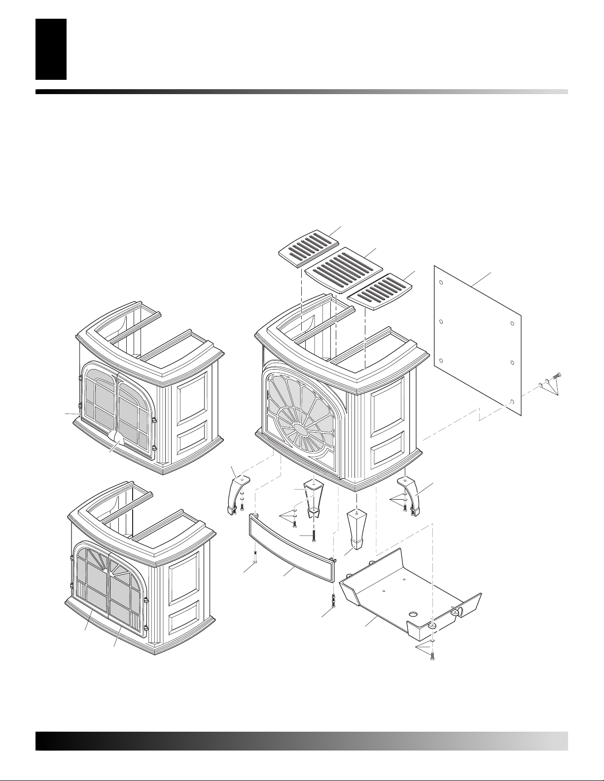
ILLUSTRATED PARTS BREAKDOWN
36
SCIVF, PSCIVF, VH, VCIS AND PVCIS Series Stove Bodies
ILLUSTRATED PARTS
BREAKDOWN
AMITY™
SCIVF(*) AND PSCIVF(*) SERIES
VICTOR HEARTH™
VH(*) SERIES
OXFORD™
VCIS(*) AND PVCIS(*) SERIES
(* Indicates Color Suffix Designation)
1L
(Discard)
1C
Oxford™
Stove Body
8
1R
2
Amity™
Stove Body
Amity™
Only
(Discard)
7
9
3
5
7
7
6
5
5
7
8
9
3
7
4
Amity™
Only
(Discard)
7
6
Victor Hearth™
Stove Body
For more information, visit www.desatech.com
For more information, visit www.desatech.com
112126-01B
Page 37
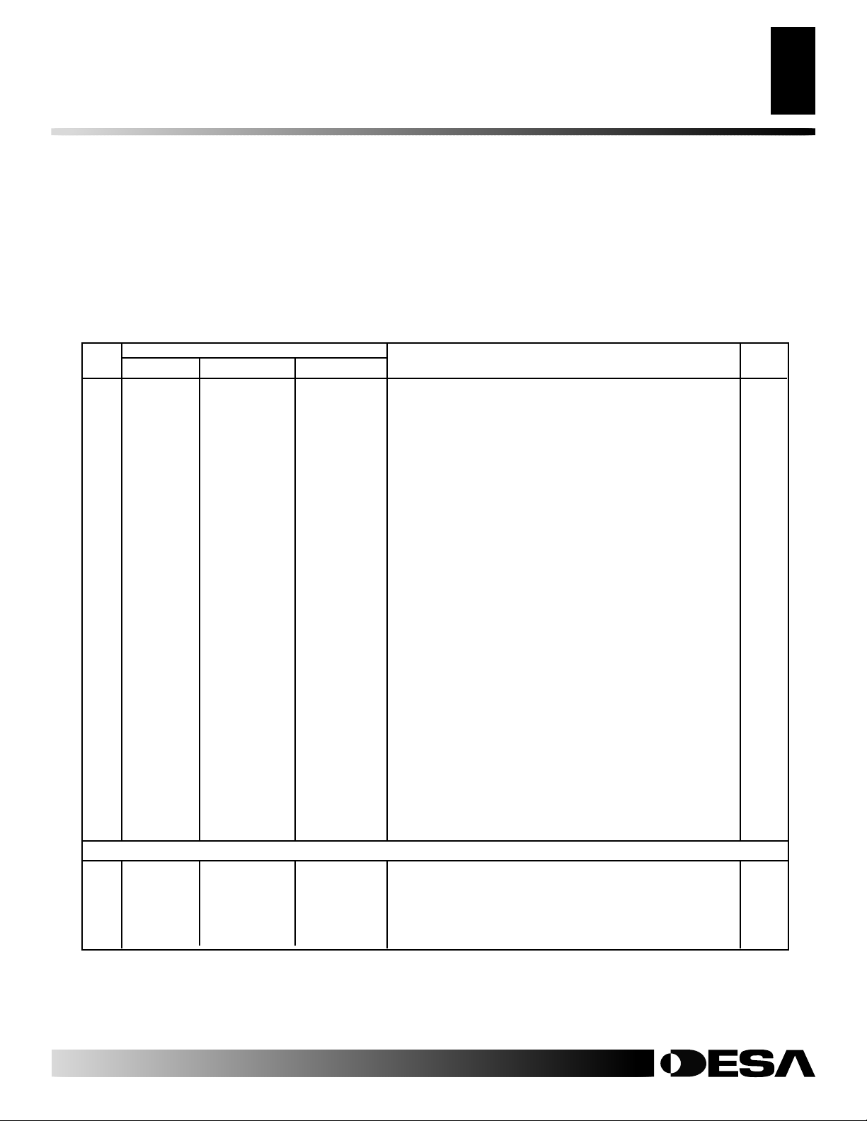
SCIVF, PSCIVF, VH, VCIS AND PVCIS Series Stove Bodies
PARTS LIST
PARTS LIST
AMITY™ SCIVF(*) SERIES, PSCIVF(*) SERIES
VICTOR HEARTH™ VH(*) SERIES
OXFORD™ VCIS(*) SERIES, PVCIS(*) SERIES
(* Indicates Color Suffix Designation)
This list contains replaceable parts used in your stove. When
ordering parts, follow the instructions listed under Replacement
Parts on page 33 of this manual.
KEY PART NO.
NO. Amity™
1C ** ** ** Top Grate with Screen, Center (Black Only) 1
1L 104171-11 104171-11 104171-11 Top Grate with Screen, Left (Black Only) 1
1R 104171-12 104171-12 104171-12 Top Grate with Screen, Right (Black Only) 1
2 ** ---- ---- Amity Stove Back Panel (Black Only) 1
3 104173-01 104173-01 104173-01 Bottom Door (Charcoal) 1
104173-07 104173-07 104173-07 Bottom Door (Porcelain Enamel Red) 1
104173-08 104173-08 104173-08 Bottom Door (Porcelain Enamel Green) 1
104173-09 104173-09 104173-09 Bottom Door (Porcelain Enamel Sand) 1
104173-23 104173-23 104173-23 Bottom Door (Porcelain Enamel Black) 1
4 ** ---- ---- Amity Stove Dropped Bottom 1
5 104175-01 104175-01 104175-01 One Leg (Charcoal) (4 Total Per Stove) 1
104175-07 104175-07 104175-07 One Leg (Porcelain Enamel Red) (4 Total Per Stove) 1
104175-08 104175-08 104175-08 One Leg (Porcelain Enamel Green) (4 Total Per Stove) 1
104175-09 104175-09 104175-09 One Leg (Porcelain Enamel Sand) (4 Total Per Stove) 1
104175-44 104175-44 104175-44 One Leg (Porcelain Enamel Black) (4 Total Per Stove) 1
6 104176-01 104176-01 104176-01 Leg Leveler bolt M8 x 1.25 - 55mm Long (4 Total Per Stove) 1
7 104177-01 104177-02 104177-02 Hardware Kit 1
8 ---- 111972-01 113086-01 Left Door, Charcoal Black 1
---- 111972-02 113086-02 Left Door, Porcelain Enamel Black 1
---- 111972-03 113086-03 Left Door, Porcelain Enamel Green 1
---- ---- 113086-04 Left Door, Red 1
---- ---- 113086-05 Left Door, Sand 1
9 ---- 111972-04 113087-01 Right Door, Charcoal Black 1
---- 111972-05 113087-02 Right Door, Porcelain Enamel Black 1
---- 111972-06 113087-03 Right Door, Porcelain Enamel Green
---- ---- 113087-04 Right Door, Red 1
---- ---- 113087-05 Right Door, Sand 1
104108-01 104108-01 104108-01 Touch-up Spray Paint 12 oz Can (Charcoal) 1
104807-01 104807-01 104807-01 Touch-up Paint Bottle with Brush (Porcelain Enamel Red) 1
104807-02 104807-02 104807-02 Touch-up Paint Bottle with Brush (Porcelain Enamel Green) 1
104807-03 104807-03 104807-03 Touch-up Paint Bottle with Brush (Porcelain Enamel Sand) 1
104807-04 104807-04 104807-04 Touch-up Paint Bottle with Brush (Porcelain Enamel Black) 1
** Not a field replaceable part.
Victor Hearth
™
Oxford™ DESCRIPTION QTY.
PARTS AVAILABLE — NOT SHOWN
37
37
1
112126-01B
For more information, visit www.desatech.com
For more information, visit www.desatech.com
Page 38
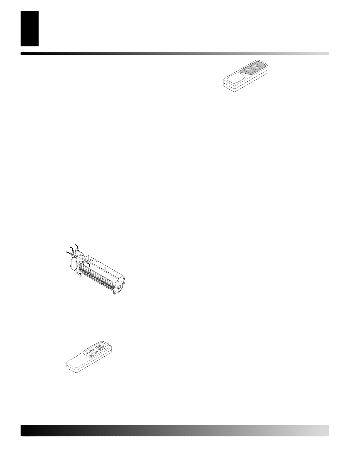
38
TECHNICAL SERVICE
SERVICE HINTS
ACCESSORIES
TECHNICAL SERVICE
You may have further questions about installation, operation, or
troubleshooting. If so, contact DESA’s Technical Service Department at 1-866-672-6040. When calling, please have your model and
serial numbers of your heater ready.
You can also visit DESA’s technical service web site at
www.desatech.com.
SERVICE HINTS
RECEIVER AND HAND-HELD REMOTE
CONTROL KIT - (C)GHRCB
For remote-ready models. Allows the gas log heater to be turned
on and off by using a hand-held remote control.
When Gas Pressure Is Too Low
• pilot will not stay lit
• burners will have delayed ignition
• burner system will not produce specified heat
• propane/LP gas supply might be low (propane/LP units only)
If you feel your gas pressure is too low, contact your local natural
or propane/LP gas supplier.
ACCESSORIES
Purchase these stove and burner system accessories from your
local dealer. If they can not supply these accessories, call DESA’s
Sales Department at 1-866-672-6040 for information. You can
also write to the address listed on the back page of this manual.
THERMOSTATICALLY- CONTROLLED
BLOWER KIT - CDA3620TB
WALL MOUNTED THERMOSTAT CONTROL
KIT - GWMT1 (Not Shown)
For all models. Allows easy wall access to the operation of your
burner system. This will allow you thermostatic control with the
convenience of a wall switch.
WALL MOUNTED ON/OFF SWITCH - GWMS2
(Not Shown)
For all models. Allows burner system to be turned on and off with
a wall switch.
NCDV-PS CONVERSION KIT (Not Shown)
For propane/LP gas models. Allows burner system to be converted from propane/LP gas to natural gas.
PCDV-NS CONVERSION KIT (Not Shown)
For natural gas models. Allows burner system to be converted
from natural gas to propane/LP gas.
STOVE HEARTH BASE - GC10SPA
(Not Shown)
For all models. Hearth base stained oak finish. Required when stove
is placed on carpet. Dimensions 4" x 35 3/4" x 30 1/2" (H x W x D).
For all models. Provides better heat distribution. Blower turns off
and on automatically, as needed. Complete installation and operation instructions included in this manual.
RECEIVER AND HAND-HELD THERMOSTAT
REMOTE CONTROL KIT - (C)GHRCTB
For remote-ready models. Allows the gas log heater to be operated
in a manually or thermostatically controlled mode. You can turn the
gas log heater on and off without ever leaving the comfort of your
easy chair.
For more information, visit www.desatech.com
For more information, visit www.desatech.com
112126-01B
Page 39
OWNER'S REGISTRATION FORM
In order to provide better customer service for this and future purchases, we recommend that you register your product with us.
You can register online at www.desatech.com. If access to our website is not available to you, please complete this Owner’s
Registration Form and mail to the address on the back of this owner’s manual. Please provide the following product information:
Brand:
Model:
Date Purchased:
Serial Number:
First Name: Last Name:
Address:
City: State: Zip: Country:
Home Phone: ( ) -
E-Mail:
Please answer the following questions to register your product with DESA:
1. Where will the product be used?
❍ Living/Family Room ❍ Office/Warehouse ❍ Utility Shed/Outbuilding ❍ Garage ❍ Bedroom ❍ Bathroom ❍ Other
2. If you bought this product yourself, did you plan to purchase this type of product before going into the store? ❍ Yes ❍ No
3. Who selected the product? ❍ Male ❍ Female ❍ Both
4. What is the population of your area? ❍ Under 10,000 ❍ 10,000 to 25,000 ❍ 25,000 to 50,000 ❍ 50,000 to 100,000
❍ 100,000 to 250,000 ❍ Over 250,000
5. What is your primary source of heat? ❍ Propane (LP Gas) ❍ Fuel Oil ❍ Wood ❍ Natural Gas ❍ Electric ❍ Other
6. How was the product installed? ❍ Professional Installer ❍ Self ❍ Other
7. Cost of product excluding sales tax? $___________________
8. Cost to install product? $____________________
9. Type of store where product was purchased? ❍ Hardware ❍ Propane Dealer ❍ Natural Gas/Utility Co. ❍ Home Center/Builder’s Supply
❍ Fireplace or Hearth Shop ❍ Farm Store ❍ Other
10. What motivated you to buy this product? ❍ Sudden Cold Weather ❍ Replace Older Model ❍ D.I.Y. Home Project
❍ Emergency Back-Up Heat ❍ Heater was on Sale ❍ Energy Savings/High Efficiency ❍ Construction Project ❍ Other
11. How did you learn about this product brand? ❍ Advertising ❍ Relative or Friend
12. Level of Education of Purchaser: ❍ Some High School ❍ Completed High School ❍ Completed College ❍ Completed Graduate School
13. Age of Purchaser: ❍ Under 20 ❍ 20 - 29 ❍ 30 - 39 ❍ 40 - 49 ❍ 50 - 59 ❍ 60 or Over
14. Buyer’s total annual household income: ❍ Under $15,000 ❍ $15,000 to $19,999 ❍ $20,000 to $34,999 ❍ $35,000 to $49,999
❍ $50,000 to $74,999 ❍ $75,000 to $99,999 ❍ $100,000 and Over
15. Store where product was purchased:
Name: ______________________________________
City: _______________________ State: __________
16. In choosing this product, how important were the following:
Availability
Price
Brand Name
Overall Quality
Heat Output
Made in USA
Warranty
Local Service
Value for Price
Prior Brand Experience
Controls Location
Thermostat, Remote, or Manual Operation
Ease of Operation
Special Features
Salesperson’s Recommendation
Friend/Relative’s Recommendation
Portability
Quiet Operation
112126-01B
For more information, visit www.desatech.com
For more information, visit www.desatech.com
Not Important Somewhat Important Very Important
(Comfort Glow, Vanguard, etc.)
(EFP33PR, VTGH33NR, etc.)
Note:
Keep receipt for warranty verification.
7 or 9 digit number located on product or identification tag.
❍ Store Display ❍ Other ________________________
❍
❍
❍
❍
❍
❍
❍
❍
❍
❍
❍
❍
❍
❍
❍
❍
❍
❍
❍
❍
❍
❍
❍
❍
❍
❍
❍
❍
❍
❍
❍
❍
❍
❍
❍
❍
❍
❍
❍
❍
❍
❍
❍
❍
❍
❍
❍
❍
❍
❍
❍
❍
❍
❍
39
39
Page 40

40
TAPE
2701 Industrial Drive
P.O. Box 90004
Bowling Green, KY 42102-9004
Postage
Required
For more information, visit www.desatech.com
For more information, visit www.desatech.com
TAPE
112126-01B
Page 41

NOTES
_______________________________________________________________________________________________
_______________________________________________________________________________________________
_______________________________________________________________________________________________
_______________________________________________________________________________________________
_______________________________________________________________________________________________
_______________________________________________________________________________________________
_______________________________________________________________________________________________
_______________________________________________________________________________________________
_______________________________________________________________________________________________
_______________________________________________________________________________________________
_______________________________________________________________________________________________
41
41
_______________________________________________________________________________________________
_______________________________________________________________________________________________
_______________________________________________________________________________________________
_______________________________________________________________________________________________
_______________________________________________________________________________________________
_______________________________________________________________________________________________
_______________________________________________________________________________________________
_______________________________________________________________________________________________
_______________________________________________________________________________________________
_______________________________________________________________________________________________
_______________________________________________________________________________________________
_______________________________________________________________________________________________
_______________________________________________________________________________________________
_______________________________________________________________________________________________
_______________________________________________________________________________________________
_______________________________________________________________________________________________
_______________________________________________________________________________________________
_______________________________________________________________________________________________
_______________________________________________________________________________________________
_______________________________________________________________________________________________
_______________________________________________________________________________________________
_______________________________________________________________________________________________
_______________________________________________________________________________________________
For more information, visit www.desatech.com
For more information, visit www.desatech.com
112126-01B
Page 42
42
WARRANTY INFORMATION
KEEP THIS WARRANTY
Burner System Model No. ________________
Serial No. ____________________________
Date Purchased _______________________
Always specify model and serial numbers when communicating with the factory.
We reserve the right to amend these specifications at any time without notice. The only warranty applicable is our standard written warranty. We make
no other warranty, expressed or implied.
Cast Stove Model No. ___________________
Serial No. ____________________________
Date Purchased _______________________
DESA LIMITED WARRANTY
DIRECT-VENT BURNER SYSTEM PLUS AMITY™ AND VICTOR HEARTH™ STOVE CHASSIS
DESA warrants this product to be free from defects in materials and components for four (4) years from the date of first purchase, provided that
the product has been properly installed, operated and maintained in accordance with all applicable instructions. To make a claim under this warranty
the Bill of Sale or cancelled check must be presented.
This warranty is extended only to the original retail purchaser. This warranty covers the cost of part(s) required to restore this stove and burner
system to proper operating condition and an allowance for labor when provided by a DESA Authorized Service Center. Warranty part(s) MUST
be obtained through authorized dealers of this product and/or DESA who will provide original factory replacement parts. Failure to use original
factory replacement parts voids this warranty. The stove and burner system MUST be installed by a qualified installer in accordance with all local
codes and instructions furnished with the unit.
This warranty does not apply to parts that are not in original condition because of normal wear and tear, or parts that fail or become damaged as a result
of misuse, accidents, lack of proper maintenance or defects caused by improper installation. Travel, diagnostic cost, labor, transportation and any and
all such other costs related to repairing a defective stove and burner system will be the responsibility of the owner.
TO THE FULL EXTENT ALLOWED BY THE LAW OF THE JURISDICTION THAT GOVERNS THE SALE OF THE PRODUCT; THIS
EXPRESS WARRANTY EXCLUDES ANY AND ALL OTHER EXPRESSED WARRANTIES AND LIMITS THE DURATION OF ANY
AND ALL IMPLIED WARRANTIES, INCLUDING WARRANTIES OF MERCHANTABILITY AND FITNESS FOR A PARTICULAR
PURPOSE TO FOUR (4) YEARS ON ALL COMPONENTS FROM THE DATE OF FIRST PURCHASE; AND DESA’S LIABILITY IS
HEREBY LIMITED TO THE PURCHASE PRICE OF THE PRODUCT AND DESA SHALL NOT BE LIABLE FOR ANY OTHER DAMAGES
WHATSOEVER INCLUDING INDIRECT, INCIDENTAL OR CONSEQUENTIAL DAMAGES.
Some states do not allow a limitation on how long an implied warranty lasts or an exclusion or limitation of incidental or consequential damages,
so the above limitation on implied warranties, or exclusion or limitation on damages may not apply to you.
This warranty gives you specific legal rights, and you may also have other rights that vary from state to state.
For information about this warranty write:
2701 Industrial Drive
P.O. Box 90004
Bowling Green, KY 42102-9004
www.desatech.com
112126 01
NOT A UPC
112126-01
Rev. B
03/04
For more information, visit www.desatech.com
For more information, visit www.desatech.com
112126-01B
 Loading...