

Desa ROPANE CONSTRUCTION HEATER User Manual
PROPANE CONSTRUCTION
HEATER
TM
OWNER’S MANUAL
For more information, visit www.desatech.com
For more information, visit www.desatech.com
Variable
30,000, 40,000,
50,000 Btu/Hr
IMPORTANT: Read and understand this manual before assembling, starting or servicing
heater. Improper use of heater can cause serious injury. Keep this manual for future reference.
GENERAL HAZARD WARNING:
FAILURE TO COMPLY WITH THE PRECAUTIONS AND INSTRUCTIONS PROVIDED WITH THIS
HEATER, CAN RESULT IN DEATH, SERIOUS BODILY INJURY AND PROPERTY LOSS OR
DAMAGE FROM HAZARDS OF FIRE, EXPLOSION, BURN, ASPHYXIATION, CARBON MONOXIDE POISONING, AND/OR ELECTRICAL SHOCK.
ONLY PERSONS WHO CAN UNDERSTAND AND FOLLOW THE INSTRUCTIONS SHOULD USE
OR SERVICE THIS HEATER.
IF YOU NEED ASSISTANCE OR HEATER INFORMATION SUCH AS AN INSTRUCTIONS
MANUAL, LABELS, ETC. CONTACT THE MANUFACTURER.
TABLE OF CONTENTS
SAFETY INFORMATION ............................................................ 2
PRODUCT IDENTIFICATION ..................................................... 3
UNPACKING............................................................................... 3
PROPANE SUPPLY.................................................................... 3
THEORY OF OPERATION ......................................................... 4
ASSEMBLY................................................................................. 4
INSTALLATION........................................................................... 4
VENTILATION............................................................................. 5
OPERATION ............................................................................... 5
STORAGE................................................................................... 6
MAINTENANCE .......................................................................... 6
TROUBLESHOOTING ................................................................ 7
SERVICE PROCEDURES .......................................................... 8
ILLUSTRATED PARTS BREAKDOWN AND PARTS LIST ....... 10
SPECIFICATIONS .................................................................... 12
ACCESSORIES ........................................................................ 12
REPLACEMENT PARTS .......................................................... 12
OWNER’S REGISTRATION FORM.......................................... 13
WARRANTY AND REPAIR SERVICE ........................ Back Cover
Save this manual for future reference.
Save this manual for future reference.

SAFETY INFORMATION
2
SAFETY INFORMATION
WARNINGS
WARNING: This product contains and/or generates
chemicals known to the State of California to cause
cancer or birth defects, or other reproductive harm.
WARNING: FIRE, BURN, INHALATION, AND EXPLOSION HAZARD. KEEP SOLID COMBUSTIBLES,
SUCH AS BUILDING MATERIALS, PAPER OR CARDBOARD, A SAFE DISTANCE AWAY FROM THE
HEATER AS RECOMMENDED BY THE INSTRUCTIONS. NEVER USE THE HEATER IN SPACES WHICH
DO OR MAY CONTAIN VOLATILE OR AIRBORNE
COMBUSTIBLES, OR PRODUCTS SUCH AS GASOLINE, SOLVENTS, PAINT THINNER, DUST PARTICLES
OR UNKNOWN CHEMICALS.
WARNING: NOT FOR HOME OR RECREATIONAL
VEHICLE USE.
The heater is designed for use as a construction heater in accordance
with ANSI Z83.7/CGA 2.14. Other standards govern the use of fuel
gases and heating products for specific uses. Your local authority can
advise you about these. The primary purpose of construction heaters is
to provide temporary heating of buildings under construction, alteration
or repair. Properly used, the heater provides safe economical heating.
Products of combustion are vented into the area being heated.
We cannot foresee every use which may be made of our heaters.
CHECK WITH YOUR LOCAL FIRE SAFETY AUTHORITY
IF YOU HAVE QUESTIONS ABOUT HEATER USE.
Other standards govern the use of fuel gases and heat producing products
for specific uses. Your local authorities can advise you about these.
Carbon Monoxide Poisoning: Some people are more affected by
carbon monoxide than others. Early signs of carbon monoxide
poisoning resemble the flu, with headaches, dizziness, and/or nausea. If you have these signs, the heater may not be working properly.
Get fresh air at once! Check for proper ventilation and have heater
serviced.
Propane Gas: Propane gas is odorless. An odor-making agent is
added to propane gas. The odor helps you detect a propane gas leak.
However, the odor added to propane gas may fade. Propane gas may
be present even though no odor exists.
Make certain you read and understand all warnings. Keep this
manual for reference. It is your guide to safe and proper operation
of this heater.
• Install and use heater with care. Follow all local ordinances and codes.
In the absence of local ordinances and codes, refer to the Standard for
Storage and Handling of Liquefied Petroleum Gas, ANSI/NFPA 58
and the Natural Gas Installation Code, CAN/CGA B149.2. This instructs on the safe storage and handling of propane gases.
• Use only the electrical voltage and frequency specified on
model plate.
• The electrical connections and grounding of the heater shall follow the National Electric Code, ANSI/NFPA 70, or Canadian
Electrical Code, part 1.
• Electrical grounding instructions — This appliance is equipped
with a three-prong (grounding) plug for your protection against
shock hazard and should be plugged directly into a properly
grounded three-prong receptacle.
• Use only a three-prong, grounded extension cord.
• Use only the hose and factory preset regulator provided with
the heater.
• Use only propane gas set up for vapor withdrawal.
• Provide adequate ventilation. Before using heater , provide at least
a 1.5-square-foot opening of fresh, outside air.
• This product has been approved for use in the Commonwealth
of Massachusetts.
• For indoor use only. Do not use heater outdoors.
• Do not use heater in occupied dwellings or in living or sleeping quarters.
• Do not use heater below ground level. Propane gas is heavier
than air. If a leak occurs, propane gas may sink to the lowest
possible level.
• Keep appliance area clear and free from combustible materials,
gasoline, paint thinner, and other flammable vapors and liquids.
Do not use heater in areas with high dust content.
• Minimum heater clearances from combustibles:
Outlet: 6 Ft. Sides: 2 Ft. Top: 6 Ft. Rear: 2 Ft.
• Keep heater at least six feet from propane tank(s). Do not point
heater at propane tank(s) within 20 feet.
• Keep propane tank(s) below 100° F.
• Check heater for damage before each use. Do not use a damaged heater.
• Check hose before each use of heater. If highly worn or cut,
replace before using heater.
• Locate heater on stable and level surface if heater is hot or operating.
• Not intended for use on finished floors.
• Never block air inlet (rear) or air outlet (front) of heater.
• Keep heater away from strong drafts, water spray, rain, or dripping water.
• Do not leave heater unattended.
• Keep children and animals away from heater.
• Never move, handle, or service a hot, operating, or plugged-in
heater. Severe burns may result. Wait 20 minutes after turning
heater off.
For more information, visit www.desatech.com
For more information, visit www.desatech.com
105331-01C

SAFETY INFORMATION
PRODUCT IDENTIFICATION
UNPACKING
PROPANE SUPPLY
3
3
SAFETY INFORMATION
Continued
• To prevent injury, wear gloves when handling heater.
• Never attach duct work to heater.
• Do not alter heater. Keep heater in its original state.
• Do not use heater if altered.
• Turn off propane supply and unplug heater when not in use.
• Use only original replacement parts. This heater must use design-specific parts. Do not substitute or use generic parts. Improper replacement parts could cause serious or fatal injuries.
PRODUCT IDENTIFICATION
Hot Air Outlet
(Front)
Heater Base
Piezo Ignitor
Button
Automatic Control
Valve Knob
Shell
Handle
Motor
Fan
Power
Cord
Valve Inlet
UNPACKING
1. Remove all packing items applied to heater for shipment. Keep
plastic cover caps (attached to inlet connector and hose/regulator assembly) for storage.
2. Remove all items from carton.
3. Check all items for shipping damage. If heater is damaged,
promptly inform dealer where you bought heater.
PROPANE SUPPLY
Propane gas and propane tank(s) are to be furnished by the user.
Use this heater only with a propane vapor withdrawal supply system.
See Chapter 5 of the Standard for Storage and Handling of Liquefied
Petroleum Gas, ANSI/NFPA 58 and/or CAN/CGA B149.2. Your
local library or fire department will have this booklet.
The amount of propane gas ready for use from propane tanks varies.
Two factors decide this amount:
1. The amount of propane gas in tank(s)
2. The temperature of tank(s)
This heater is designed to operate with a minimum 20-pound
propane tank. You may need two or more tanks or one larger tank
in colder weather. Use a 100-pound tank for longer operation or in
very cold weather. Less gas is vaporized at lower temperatures.
Your local propane gas dealer will help you select the proper supply
system. The minimum surrounding air temperature rating for each
heater is -20°F (-29°C).
Average Number Of
Temperature (°F) Tanks
At Tank Location (100-pound)
40° 1
32° 1
20° 1
10° 1
0° 1
-10° 2
-20 ° 2
Hose /
Regulator
Assembly
Figure 1 - 50,000 BTU/Hr Model
For more information, visit www.desatech.com
For more information, visit www.desatech.com
105331-01C
THEORY OF OPERATION
ASSEMBLY
4
INSTALLATION
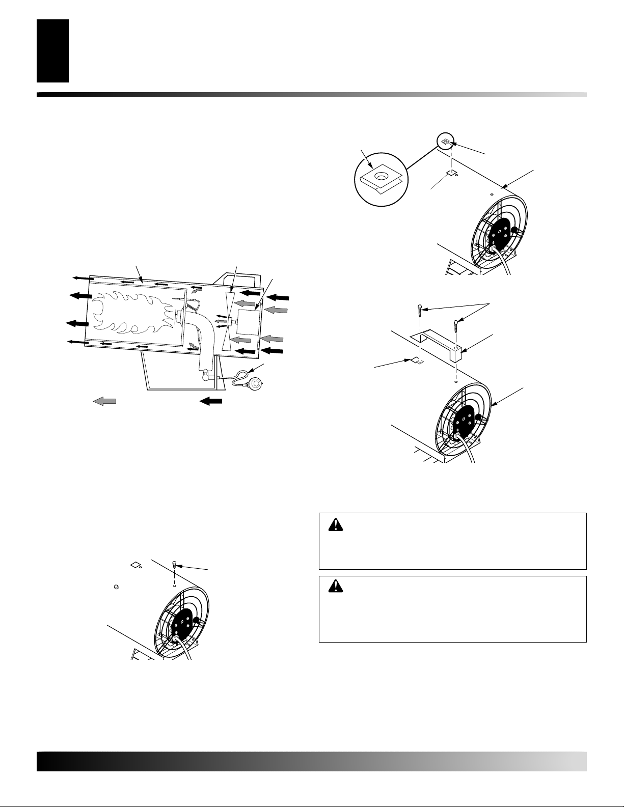
THEORY OF OPERATION
The Fuel System: The hose/regulator assembly attaches to the
propane gas supply. This provides fuel to the heater.
The Air System: The motor turns the fan. The fan pushes air into and
around the combustion chamber. This air is heated and provides a
stream of clean, hot air.
The Ignition System: The piezo ignitor lights the burner.
The Automatic Control System: This system causes the heater to
shut down if the flame goes out.
Combustion
Chamber
Clean
Heated
Air Out
(Front)
Air For Combustion Air For Heating
Figure 2 - Cross Section Operational View
Fan
Motor
Cool Air
In (Back)
Hose/
Regulator
Assembly
Flat Side Facing Up
Nut Clip
Shell
Slot
Figure 4 - Installing Nut Clip
Screws
Handle
Nut Clip
Rear of
Heater
ASSEMBLY
1. Remove screw from top of fan guard (see Figure 3). Discard screw.
2. Insert nut clip (provided with handle) with flat side facing up
through slot in top of shell. Align holes in nut clip with screw
hole behind slot in top of shell. (see Figure 4).
3. Place handle over hole and clip. Insert two screws (provided with
handle) through handle and tighten into shell. Make sure rear screw
goes through shell and into fan guard. Tighten screws firmly.
Screw
Figure 3 - Removing Screw from Top of Fan Guard
Figure 5 - Attaching Handle
INSTALLATION
WARNING: Review and understand the warnings
in the
Safety Information
are needed to safely operate this heater. Follow all
local codes when using this heater.
WARNING: Test all gas piping and connections
for leaks after installation or servicing. Never use an
open flame to check for a leak. Apply a mixture of
liquid soap and water to all joints. Bubbles forming
show a leak. Correct all leaks at once.
1. Provide propane supply system (see Propane Supply, page 3).
2. Connect fuel gas fitting on hose/regulator assembly to propane tank(s). Turn fuel gas fitting counterclockwise into threads
on tank. Tighten firmly using a wrench.
tion regulator so that hose leaving the regulator is in a horizontal position (see Figure 6, page 5). This places the regulator vent in the proper position to protect it from the weather.
section, pages 2 and 3. They
IMPORTANT:
Posi-
For more information, visit www.desatech.com
For more information, visit www.desatech.com
105331-01C

INSTALLATION
VENTILATION
OPERATION
To Start Heater
5
5
INSTALLATION
Continued
3. Connect hose to valve inlet. Tighten firmly using a wrench.
You must use the regulator supplied with heater.
4. Open propane supply valve on propane tank(s) slowly.
If not opened slowly, excess-flow check valve on propane tank
may stop gas flow . If this happens, close propane supply valve
and open again slowly.
5. Check all connections for leaks. Apply mixture of liquid soap
and water to gas joints. Bubbles forming show a leak that must
be corrected.
6. Close propane supply valve.
WARNING: Never use an open flame to check for
a leak. Apply a mixture of liquid soap and water to all
joints. Bubbles forming show a leak that must be
corrected. Correct all leaks at once.
Regulator
Propane
Supply
Valve
Propane
Tank
Figure 6 - Regulator Position
Fuel Gas
Fitting
Note:
Hose
VENTILATION
WARNING: Provide at least a 1.5 square foot
opening of fresh, outside air while running heater. If
proper fresh, outside air ventilation is not provided,
carbon monoxide poisoning can occur. Provide proper
fresh, outside air ventilation before running heater.
OPERATION
WARNING: Review and understand the warnings
in the
Safety Information
are needed to safely operate this heater. Follow all
local codes when using this heater.
TO START HEATER
1. Follow all installation, ventilation, and safety information.
2. Locate heater on stable and level surface. Make sure strong
drafts do not blow into front or rear of heater.
3. Plug power cord of heater into a three-prong, grounded extension cord. Extension cord must be at least six feet long. Extension cord must be UL listed.
Extension Cord Wire Size Requirements
Up to 50 feet long, use 18 AWG rated cord. 51 to 100 feet
long, use 16 AWG rated cord. 101 to 200 feet long, use 14
AWG rated cord.
4. Plug extension cord into a 120 volt/60 hertz, 3-hole, grounded
outlet. Motor will start. Fan will turn, forcing air out front of heater.
5. Open propane supply valve on propane tank(s) slowly.
If not opened slowly, excess-flow check valve on propane tank
may stop gas flow . If this happens, close propane supply valve
and open again slowly.
section, pages 2 and 3. They
Note:
Knob
Valve Inlet
Hose
Figure 7 - Hose and Inlet Connector
For more information, visit www.desatech.com
For more information, visit www.desatech.com
105331-01C
WARNING: Be sure motor and fan are running before
pushing in automatic control valve button. Flames could
flash outside heater if motor and fan are not running.
6. Turn control knob to the low position and push in (see Figure
8 and 9, page 6). Hold knob in and push piezo ignitor button.
You may need to push piezo ignitor button 3-8 times until the
main burner lights. When main burner lights, keep automatic
control valve knob pushed in. Release button after 30 seconds.
Note:
If main burner fails to light, hose may have air in it. If
so, keep control knob pressed and wait 20 seconds. Release
control knob and wait 20 seconds for unburned fuel to exit
heater. Repeat step 6.
 Loading...