

Desa R55A, REM55A, R60, RM60, REM60 Service Manual
...
SECTION A
SERVICE MANUAL
LOW PRESSURE
PORTABLE FORCED AIR HEATER
HOT SURFACE IGNITION MODELS

Hot Surface Ignition Models Service Manual
For replacement parts contact:
www.PartsFor.com
SAFETY INFORMATION
WARNINGS
IMPORTANT: Read this owner’s manual carefully and
completely before trying to assemble, operate, or service this heater. Improper use of this heater can cause
serious injury or death from burns, fire, explosion,
electrical shock, and carbon monoxide poisoning.
DANGER: Carbon monoxide poisoning may lead
to death!
Carbon Monoxide Poisoning: Early signs of carbon monoxide
poisoning resemble the flu, with headaches, dizziness, and/
or nausea. If you have these signs, the heater may not be
working properly. Get fresh air at once! Have heater serviced. Some people are more affected by carbon monoxide
than others. These include pregnant women, persons with
heart or lung disease or anemia, those under the influence of
alcohol, and those at high altitudes.
Make certain you read and understand all warnings. Keep this
manual for reference. It is your guide to safe and proper
operation of this heater.
• Use only kerosene or No. 1 fuel oil to avoid risk of fire or
explosion. Never use gasoline, naphtha, paint thinners,
alcohol, or other highly flammable fuels.
• Fueling
a)Personnel involved with fueling shall be qualified and
thoroughly familiar with the manufacturer’s instructions
and applicable federal, state, and local regulations regarding the safe fueling of heating units.
b)Only the type of fuel specified on the heater’s data plate
shall be used.
c)All flame, including the pilot light, if any, shall be extin-
guished and the heater allowed to cool, prior to fueling.
d)During fueling, all fuel lines and fuel-line connections
shall be inspected for leaks. Any leaks shall be repaired
prior to returning the heater to service.
e)At no time shall more than one day’s supply of heater
fuel be stored inside a building in the vicinity of the
heater. Bulk fuel storage shall be outside the structure.
f) All fuel storage shall be located a minimum of 25 feet
from heaters, torches, welding equipment, and similar
sources of ignition (exception: the fuel reservoir integral
with the heater unit).
g)Whenever possible, fuel storage shall be confined to
areas where floor penetrations do not permit fuel to
drip onto or be ignited by a fire at lower elevation.
h)Fuel storage shall be in accordance with the federal,
state, or local authority having jurisdiction.
• Never use heater where gasoline, paint thinner, or other
highly flammable vapors are present.
• Follow all local ordinances and codes when using heater.
• Heaters used in the vicinity of tarpaulins, canvas, or similar enclosure materials shall be located a safe distance
from such materials. The recommended minimum safe
distance is 10 feet. It is further recommended that these
enclosure materials be of a fire retardant nature. These
enclosure materials shall be securely fastened to prevent them from igniting or from upsetting the heater due
to wind action.
• Use only in well-vented areas. Before using heater, provide at least a three-square-foot opening of fresh, outside
air for each 100,000 Btu/Hr of rating. This heater produces
carbon monoxide, which is listed by the State of California
as a reproductive toxin under Proposition 65.
• Use only in places free of flammable vapors or high dust
content.
• Use only the electrical voltage and frequency specified
on model plate.
• Use only a three-prong, grounded extension cord.
• Minimum heater clearances from combustibles:
Outlet: 8 Ft. Sides: 4 Ft. Top: 4 Ft. Rear: 4 Ft.
• Locate heater on a stable and level surface if heater is
hot or running or a fire may occur.
• When moving or storing heater, keep heater in a level
position or fuel spillage may occur.
• Keep children and animals away from heater.
• Unplug heater when not in use.
• When used with thermostat, heater may start anytime.
• Never use heater in living or sleeping areas.
• Never block air inlet (rear) or air outlet (front) of heater.
• Never move, handle, refuel, or service a hot, operating,
or plugged-in heater.
• Never attach duct work to front or rear of heater.
• Approved by the New York City Fire Department under
certificate of approval #4803, #4860, #4908, or #4909.
To be used only at construction sites in accordance with
applicable New York City Codes, Regulations, Rules,
Directives, Permits, etc.
• Warning to New York City Residents For Use Only At
Construction Sites in accordance with applicable NYC
codes under NYCFD certificate of approval #4803, #4899,
#4908, #4909, or #4934.
2

Hot Surface Ignition Models Service Manual
For replacement parts contact:
www.PartsFor.com
TABLE OF CONTENTS
General Information
I. Arrangement of Manual.....................................3
III. Service Preparation...........................................3
IV. Tools Required ..................................................4
V. Parts.................................................................. 4
Specifications
I. General Specifications
1. Fuel Selection...............................................5
2. Electrical....................................................... 5
3. Ventilation.....................................................5
4. Heater Sizing................................................ 5
II. Heater Performance Specifications................... 6
Component Operation
I. Air System
1. Air Pump.......................................................7
2. Air Filters ...................................................... 7
3. Nozzle ..........................................................7
II. Electrical System
1. Motors ..........................................................7
2. Ignition Control/Photocell .............................8
3. Hot Surface Ignitor .......................................8
III. Fuel System ...................................................... 8
IV. Combustion System..........................................9
V. All Systems Working Together .......................... 9
Troubleshooting
I. Safety Requirements.......................................10
II. Cautions .......................................................... 10
III. Using The HA1 170 Tester
1. Operation....................................................10
2. Calibration .................................................. 10
IV. Diagnostic Charts............................................10
GENERAL INFORMATION
I. ARRANGEMENT OF MANUAL
This manual contains information and service procedures to
assist the service technician in understanding and correcting
problems on DESA International oil-fired portable forced air
heaters. The first section of the manual contains basic information concerning the operation of the different components
in the heater. This information should be reviewed by service
personnel to provide a basic understanding of how the components function in the working system. The
section of this manual is intended to provide a quick reference
concerning conditions which result in customer complaints.
These procedures will help the service technician quickly
diagnose a malfunctioning heater. The illustrations in this
manual may not necessarily depict the actual heater model,
and are intended for reference ONLY.
III. SERVICE PREPARATION
A clean work area at the start of each job is essential for
efficient service work. Heaters which are extremely dirty
should be cleaned prior to service. Cleaning will occasionally
uncover the problem area. Tools needed for the job should be
obtained before work is started. Delays resulting from locating
tools result in lost time and wages.
Clean fuel should always be used when testing heaters. Many
problems are often traced to the use of the wrong type of fuel
or dirty fuel.
Use caution and common sense when working on a heater.
Always remember that kerosene is flammable, and electrical
parts can result in potential shock. Heater parts are hot during
operation, which could result in burns.
Troubleshooting
Wiring Diagrams.................................................23
3
Hot Surface Ignition Models Service Manual
For replacement parts contact:
www.PartsFor.com
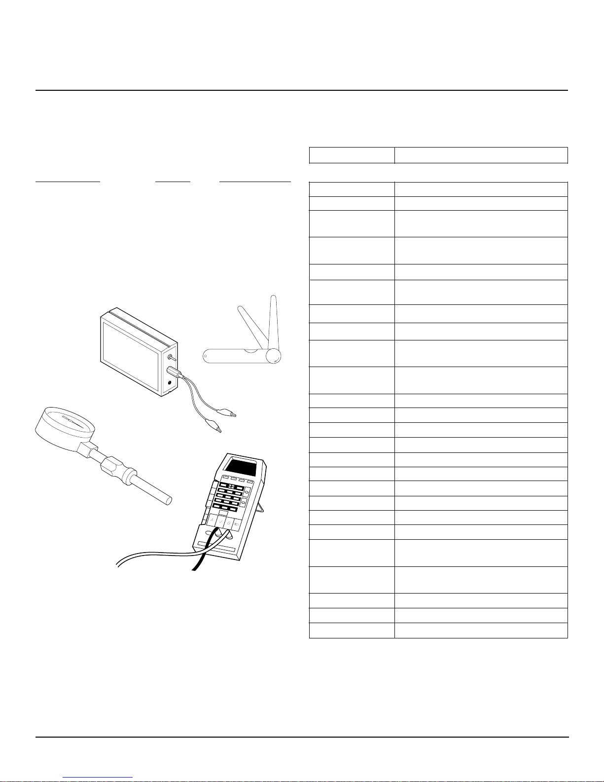
IV. TOOLS REQUIRED
In addition to common hand tools, the service shop should
have the following tools and instruments for proper repairing
of the heaters. These instruments will be referred to throughout this manual.
INSTRUMENT RANGE PART NUMBER
Control/Photocell Tester N/A HA1170
Pressure Gauge 0-15 P. S. I. HA1180
Feeler Gauge .001 to .1 inch None*
Multimeter 0-250 VAC None**
0-200 Ohm
*Available at any auto parts store.
**Available at most electronic stores.
HA1170
Control
Tester
Pressure Gauge
Feeler
Gauge
.025
.0015
Multimeter
V. PARTS
In addition to the standard parts we now offer parts kits. Listed
below are the item numbers and the accessory description
ITEM NUMBER ACCESSORY
HA1180 Air Gauge/All Models
HA1210 Thermostat/Forced Air & LP Forced Air
HA1202 Heavy Duty Wheel Kit
Fits: 35, 40, 50, 55, 60, 70 Models
HA1206 Wheel Kit
Fits: 35, 40, 50, 55, 60, 70 Models
HA2203 Rear Handle Fits: 110, 115 Models
HA2204 Rear Handle
Fits: 150, 155, 165, 200 Models
HA2210 Filler Neck Screen
ITEM NUMBER REPLACEMENT PART
104068-03 Ignition control
Fits: 35, 40, 50, 55, 60 Models
104068-02 Ignition control Fits: 70, 110, 115,
150, 155, 165, 200 Models
PP204 Rotor Kit 1/2"
PP206 Nozzle (35, 40 Models)
Refer to Owner’s Manual Nozzle (50/55 Models)
PP219 Nozzle (60 Models)
PP220 Nozzle (70 Models)
PP221 Nozzle (110, 115 Models)
PP222 Nozzle (150, 155 Models)
PP223 Nozzle (165 Models)
PP235 Nozzle (200 Models)
PP200 Hot Surface Ignitor
PP213 Air Filter Kit
(35, 40, 50, 55, 60, 70
PP214 Filter Kit
(110, 115, 150, 155, 165,
PP205 Rotor Kit 5/8"
M16656-24 Photocell
PP217 Pump Adjustment Kit
Models)
200 Models)
4

Hot Surface Ignition Models Service Manual
For replacement parts contact:
www.PartsFor.com
SPECIFICATIONS
I. GENERAL SPECIFICATIONS
1. Fuel Selection
One of the most critical specifications for trouble-free operation is the use of a clean, acceptable fuel. Listed below are
guidelines and comments concerning operation of heaters
with different fuels.
RECOMMENDED COMMENTS
FUELS
Kerosene
Fuel Oil No.1
Jet "A"
ALTERNATE FUELS COMMENTS
Fuel Oil No. 2
Diesel No. 1
Diesel No. 2
2. Electrical
The heater must be connected to a standard electrical outlet
(120V/60HZ). For safety, all heaters are equipped with a three
prong power cord, which must be grounded. When selecting
an extension cord for heater usage, the following chart should
be used in determining wire size.
LENGTH OF CORD WIRE SIZE (AWG)
100 Ft. No. 14
200 Ft. No. 12
300 Ft. No. 10
400 Ft. No. 8
Best overall results. Minimum odor and
minimum maintenance. No additives
necessary for cold weather operation.
Noticeable increase in odor. Requires
frequent maintenance of fuel filter
and nozzle. Requires a winterizing
additive at temperatures below 20°F
No. 6
3. Ventilation
The heater should be used only in well-ventilated areas. As a
rule, the following minimum requirements should be followed.
HEATER SIZE (BTU) SQUARE FOOT OPENING
35,000/40,000 1.0 Sq. Ft.
50,000/55,000/60,000 1.6 Sq. Ft.
70,000 2.1 Sq. Ft.
110,000/115,000 3.2 Sq. Ft.
150,000/155,000 4.5 Sq. Ft.
165,000 5.0 Sq. Ft.
200,000 6.0 Sq. Ft.
The above is based on ventilation requirements of at least a
3 sq. ft. opening per 100,000 BTU. If possible, it is better to
provide cross-ventilation to achieve better air movement.
4. Heater Sizing
The user should be aware of the proper size heater needed
for a particular application. It is easy to see that a 35,000 BTU
heater would not heat a large warehouse, but the question is
sometimes asked "What size heater should I use?" A simple
formula that can be used to determine heater BTU requirements follows:
Cu. Ft. of Area X .133 X Desired Temp. Rise °F = BTU Size
Needed.
Example:
Area: 50' X 25' X 10' = 12,500 Cu. Ft.
Desired Temp. Rise: 30°F
12,500 (Cu. Ft.)
X .133 (Factor)
1662.5
X 30 (Temp. Rise)
49,875 (Proper Heater Size)
ANSWER:
heater should be selected
for this application.
A 50,000 BTU
5

Hot Surface Ignition Models Service Manual
For replacement parts contact:
www.PartsFor.com
II. HEATER PERFORMANCE SPECIFICATIONS
Technical Service Heater Performance Data
Heater Model BTU Pump Nozzle Nozzle Motor Motor Motor Ignitor Control Fuel Hot Air AMPS
R35D 35,000 3.0 100735-02 0.30 100088-01 1725 1/15 102548-03 104068-03 3.0 165 2.0
REM35C (HA3006) (102001-01)
R40 40,000 3.0 100735-02 0.30 100088-01 1725 1/15 102548-03 104068-03 3.0 170 2.0
REM40 (HA3006) (102001-01)
R55A 55,000 3.6 100735-17 0.40 100088-01 1725 1/15 102548-03 104068-03 5.0 175 2.0
REM55A (HA3024) (102001-01)
R60 60,000 3.4 100735-17 0.40 100088-01 1725 1/15 102548-03 104068-03 5.0 180 2.0
REM60 (HA3024) (102001-01)
RM60
R70D 70,000 4.7 100735-18 0.50 103609-01 3450 1/8 102548-03 104068-02 5.0 250 2.8
R70DT (HA3026) (102001-20)
R110B 110,000 5.3 100735-19 0.80 103493-01 3450 1/5 102548-03 104068-02 9.0 490 3.6
R110BT (HA3027) (102001-21)
R115 115,000 5.3 100735-19 0.80 103493-01 3450 1/5 102548-03 104068-02 9.0 490 3.6
REM115 (HA3027) (102001-21)
RM115
REM150E 150,000 5.4 100735-20 1.10 103493-01 3450 1/5 102548-03 104068-02 13.5 550 3.6
R155B 155,000 5.4 100735-20 1.10 103493-01 3450 1/5 102548-03 104068-02 13.5 550 3.6
REM155B (HA3028) (102001-21)
RM155
R165AT 165,000 5.6 100735-21 1.20 103493-01 3450 1/5 102548-03 104068-02 13.5 575 3.6
R200A 200,000 6.2 100735-31 1.40 105183-01 3400 1/4 102548-03 104068-02 13.5 600 3.6
Rating PSI Part No. GPH Part No. R.P.M. Horsepower Kit Board Tank Output (Running)
± .1 ± 5% Capacity (C.F.M.)
(Gal)
(HA3028) (102001-21)
(HA3029) (102001-21)
(102001-27)
M16656-24 Photocell will apply to all models for service.
6
Hot Surface Ignition Models Service Manual
AC LINE
CAPACITOR
AUX
MAIN
For replacement parts contact:
www.PartsFor.com
COMPONENT OPERATION
I. AIR SYSTEM
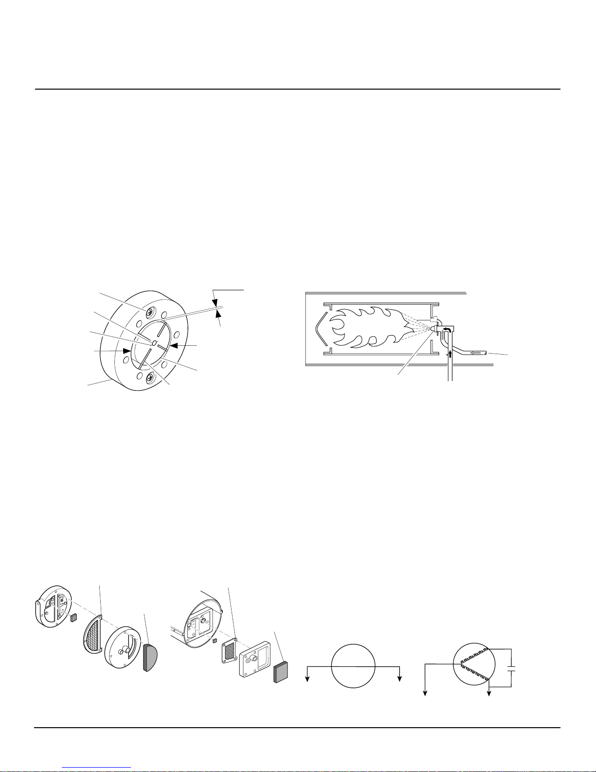
1. Air Pump
The heater's air pump consists of a rotor with four carbon
blades rotating inside a pump body. The rotor is driven directly
by the motor and is attached to the motor shaft by means of
a plastic insert. As the motor rotates, the carbon blades travel
outward rubbing against the inside surface of the steel pump
body. The rotor's position inside the pump body is such that
it is not concentric with the pump body and a .003/.004 of an
inch gap is set at the uppermost quadrant. As the motor
rotates, the air between the blades is compressed and routed
to the nozzle through the air line.
Gap Adjusting
Screw
Motor Shaft
Insert
Air Output
Side
Pump Body
Air Intake Side
Rotor
Blade
.003/.004
Clearance
Measured
with Feeler
Gage
3. Nozzle
As mentioned previously, the purpose of the air pump is to
compress air and deliver it to the nozzle. The compressed air,
as it travels through the nozzle, creates a negative pressure
that extends back through the center of the nozzle. This
negative pressure lifts the fuel from the fuel tank. The fuel from
the fuel tank and the compressed air are mixed at the nozzle
which results in a very fine mist of fuel being sprayed into the
combustion chamber. The air pump/nozzle combination eliminates the need for a conventional type fuel pump. It is
important for the service technician to understand the nozzle
operation. In many cases concerning improper operation of a
heater, the problem is the result of a seal leak or a restriction
(dust/dirt) being present within the nozzle. It should also be
pointed out that each model heater requires different nozzles
due to different fuel flow rates.
Compressed
Air From
Pump
Nozzle Face
Fuel Lifted From Tank
by Negative Pressure
Direction of Rotation-Clockwise
2. Air Filters
The air filtering system consists of an air input filter and an air
output filter. The air input filter is located at the right rear of the
motor and its purpose is to filter all incoming air prior to
entering the air pump. The filter design is such that it can be
cleaned in a mild, soapy solution, thoroughly dried and used
over again. The air output filter is located under the plastic end
cover. This filter's purpose is to prevent any carbon dust (from
rotor or blade wear) from entering the air passages in the
nozzle. This filter is non-cleanable and should be replaced
when considerable buildup of carbon dust is observed. (See
drawings below).
Air Output Filter
Air Input
Filter
35,000, 50,000, 55,000, and
70,000 BTU
Filter System
155,000, 165,000, and 200,000
Air Output Filter
Air Input
Filter
110,000, 115,000, 150,000,
BTU Filter System
II. ELECTRICAL SYSTEM
1. Motors
The motors used on the low pressure heaters are fractional
horsepower motors ranging from 1/15 HP on the smallest
heater to 1/4 HP on the largest heaters. The motors used can
be grouped into two categories. The first category is the
shaded pole motor. The shaded pole motor contains a single
winding and does not require an integral start/run capacitor for
operation. This type of motor is used on 35, 40, 50, 55, and 60
model heaters.
The second category is the permanent start capacitor motor.
This motor contains two separate windings. The first winding
being the auxiliary or start winding and the second being the
main or run winding. This motor utilizes an integral start/run
capacitor which is wired internally and cannot be replaced.
This type of motor is used on the 70, 110, 115, 150, 155, 165,
and 200,000 Btu models.
MOTOR
AC LINE
Shaded Pole Motor Permanent Start Capacitor Motor
7
Hot Surface Ignition Models Service Manual
For replacement parts contact:
www.PartsFor.com
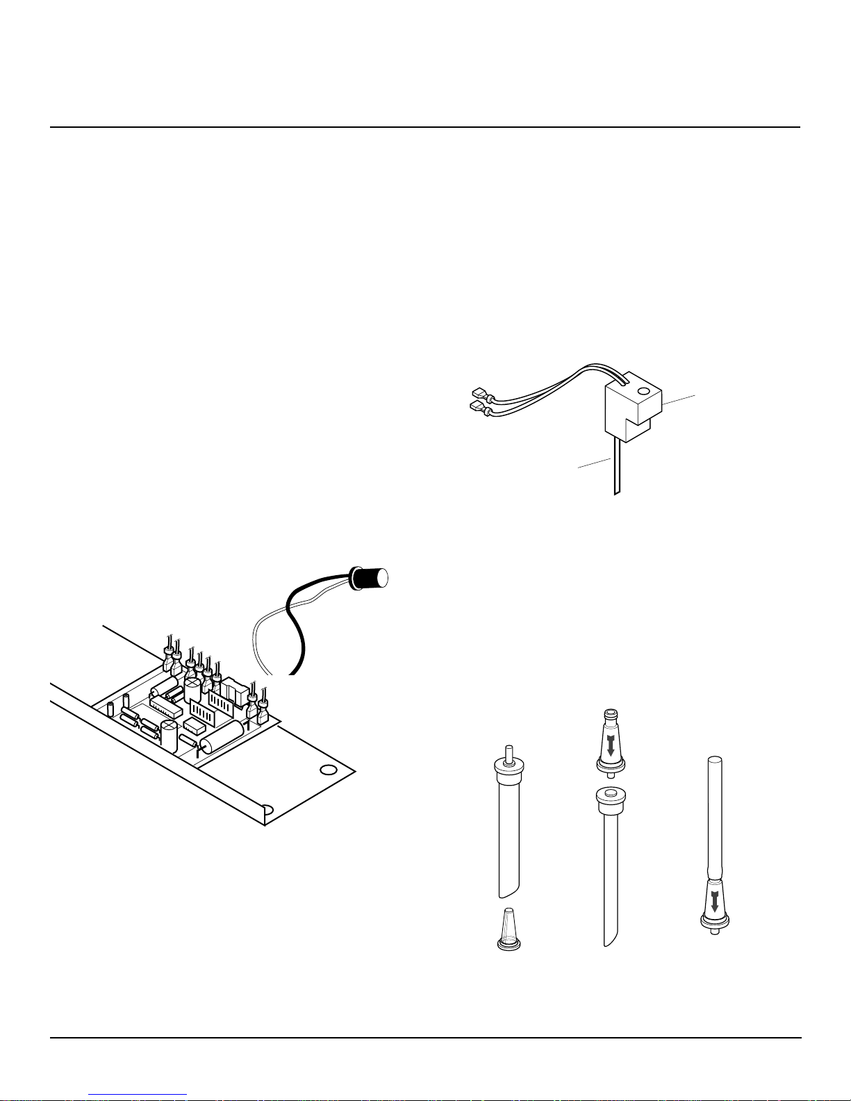
2. Ignition Control/Photo Cell
The ignition control circuit consists of a photocell (light sensitive resistor) and an ignition control. The photocell is used to
sense the presence of light inside the combustion chamber.
The resistance of the photocell changes as the light level
inside the combustion chamber changes. When the heater is
operating properly, the flame pattern inside the combustion
chamber is very turbulent which results in the resistance of the
photocell increasing and decreasing very rapidly. This dynamic change in resistance is required by the ignition control
to allow the heater to continue to operate. If the signal from the
photocell becomes “lazy” or steady state indicating a lack of
turbulence, then the heater will be turned off. Some examples
of this condition are a loss of fan and a blocked inlet. Because
the photocell also responds to the color of the flame, the
control will also shut off the heater if the fuel/air mixture is too
lean. With a fuel lean mixture the flame becomes blue in color
and the photocell does not respond to that end of the light
spectrum as well as it responds to orange light which is
present during proper operation. As a service technician, it is
important to understand the operation of the ignition control.
In the past, it has been the single most misdiagnosed part of
the heater. It is suggested that all controls be checked per
instructions listed in the
replacement.
Troubleshooting
section, prior to
Photocell
3. Hot Surface Ignitor
All models will use 102548-03 Ignitor Kit.
The hot surface ignitor is rated for 120 volts. With the rated
voltage applied, the ignitor element heats up to 1400º Celsius
(2550º Fahrenheit) within 5 seconds. When the atomized fuel
is sprayed by the nozzle it is ignited by this extremely hot
surface.
Note:
It is important for the service technician to be cautious
when working with the hot surface ignitor due to its extremely
high operating temperature. Care should also be taken not to
bend or strike the ignitor element.
Ignitor
Block
Ignitor Element
III. FUEL SYSTEM (FUEL FILTERS)
There are several types of fuel filters used on different model
heaters. The filters are always located in line with the fuel
pickup tube. The purpose of the filter is to eliminate the
possibility of dirt, dust, etc. from entering the nozzle and
restricting the flow. The filters should be inspected and
cleaned whenever a heater is brought in for service. It is also
important that the bottom of the tank be inspected for sedimentation or dirt buildup. The filter’s design is such that a
possible restriction in the filter screen can be present during
operation and be dislodged back into the tank when the heater
is shut off.
Ignition Control
(mounted on side cover)
35, 40, 50, 55,
60, and 70,000
8
Btu Models
110, 115, 150,
155, and 165,000
Btu Models
200,000 Btu
Model
 Loading...