

Desa RC40, RC55T, RC70T, RC115T, RC165T Owner's Manual
For more information, visit www.desatech.com
For more information, visit www.desatech.com
50 SIDE PFA/PV 010A
Models: RC40, RC55T, RC70T,
RC115T and RC165T
CANADIAN PORTABLE
TM
FORCED AIR HEATERS
OWNER’S MANUAL
IMPORTANT
Read and understand this manual before assembling, starting, or servicing heater.
Improper use of heater can cause serious injury. Keep this manual for future reference.
TABLE OF CONTENTS
SAFETY INFORMATION ............................................................ 2
PRODUCT IDENTIFICATION ..................................................... 3
UNPACKING............................................................................... 3
ASSEMBLY................................................................................. 3
THEORY OF OPERATION ......................................................... 4
FUELS......................................................................................... 5
VENTILATION ............................................................................. 5
OPERATION ............................................................................... 5
STORING, TRANSPORTING, OR SHIPPING............................ 6
PREVENTATIVE MAINTENANCE SCHEDULE ......................... 6
TROUBLESHOOTING ................................................................ 7
SERVICE PROCEDURES .......................................................... 8
WIRING DIAGRAMS................................................................. 13
SPECIFICATIONS .................................................................... 14
ACCESSORIES ........................................................................ 15
ILLUSTRATED PARTS BREAKDOWN AND PARTS LIST ....... 16
WARRANTY AND REPAIR SERVICE ........................ Back Cover
DESA Industries of Canada, Inc. 2220 Argentina Rd. unit #4 Mississauga, Ontario LSN 2K7
Save this manual for future reference.
Save this manual for future reference.
®
SAFETY INFORMATION
2
SAFETY INFORMATION
WARNINGS
IMPORTANT: Read this owner’s manual carefully
and completely before trying to assemble, operate, or
service this heater. Improper use of this heater can
cause serious injury or death from burns, fire, explosion, electrical shock, and carbon monoxide
poisoning.
DANGER: Carbon monoxide poisoning may lead
to death!
Early signs of carbon monoxide poisoning resemble the flu, with
headaches, dizziness, and/or nausea. If you have these signs, the
heater may not be working properly. Get fresh air at once! Have
heater serviced. Some people (such as pregnant women, persons with
heart or lung disease, persons with anemia, those under the influence
of alcohol, and those at high altitudes) are more affected by carbon
monoxide than others.
Make certain you read and understand all warnings. Keep this
manual for reference. It is your guide to safe and proper operation
of this heater.
• Use only kerosene, #1/#2 diesel/fuel oil, JET A or JP-8 fuels to
avoid risk of fire or explosion. Never use gasoline, naphtha, paint
thinners, alcohol, or other highly flammable fuels.
• Use only with the electrical voltage and frequency specified on
model plate.
• Heater must be grounded. Use only a properly grounded threewire extension cord. Plug into grounded outlet only.
• Use only in areas free of flammable vapors or high dust content.
• Minimum clearance from any combustible materials: 8 feet (244
cm) from hot air outlet; 6 feet (183 cm) from top; and 2 feet (61
cm) from sides and inlet.
• Locate heater on a stable and level surface while hot or operating or a fire may occur.
• Use only in well ventilated areas. Provide ventilation of at least
three square feet (2,800 square cm) for each 100,000 Btu/Hr of
rating.
• Keep children and animals away from heater at all times.
• Never start heater when combustion chamber is hot or if fuel
has accumulated in combustion chamber.
• When used with a thermostat, heater may start at anytime.
• When heater is moved or stored, it must be in a level position or
fuel spillage may occur.
• Use heater only in accordance with local ordinances and codes.
• Never use gasoline, crankcase drainings, naphtha, paint thinners,
alcohol, or other highly flammable fuels.
• Never use heater where gasoline, paint thinner, or other highly
flammable vapors are present.
• Never use heater in living or sleeping areas.
• Never leave a heater plugged in without adult supervision if
children or animals are likely to be present.
• Never move, handle, refuel, or service a hot, operating, or
plugged-in heater.
• Never block air inlet at motor end (rear) of heater.
• Never attach duct work to front of heater.
• Never attach heater to external fuel tank.
For more information, visit www.desatech.com
For more information, visit www.desatech.com
105536
PRODUCT IDENTIFICATION
UNPACKING
ASSEMBLY
3
3
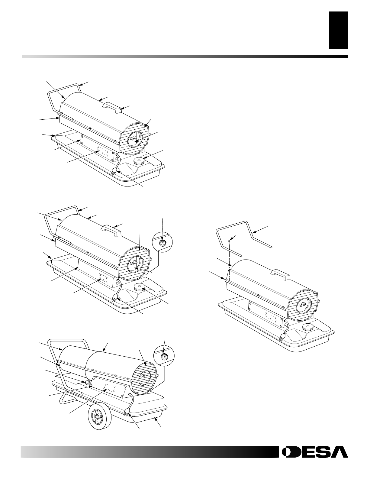
PRODUCT IDENTIFICATION
Hot Air
Outlet
Lower
Shell
Fuel
Tank
Side Cover
Ignition Control
Assembly
(assembly on inside
of side cover)
Figure 1 - 40 Model
Hot Air
Outlet
Lower
Shell
Nose Cone Guard
Upper Shell
Nose Cone Guard
Upper Shell
Handle
Handle
Fan Guard
Air Filter
End
Cover
Power Cord
Thermostat
Knob
Fan Guard
Fuel
Cap
UNPACKING
1. Remove all protective packaging that has been applied to heater
for shipment
2. Remove heater from carton.
3. Check heater for any shipping damage. If damage is found,
promptly inform dealer where heater was purchased.
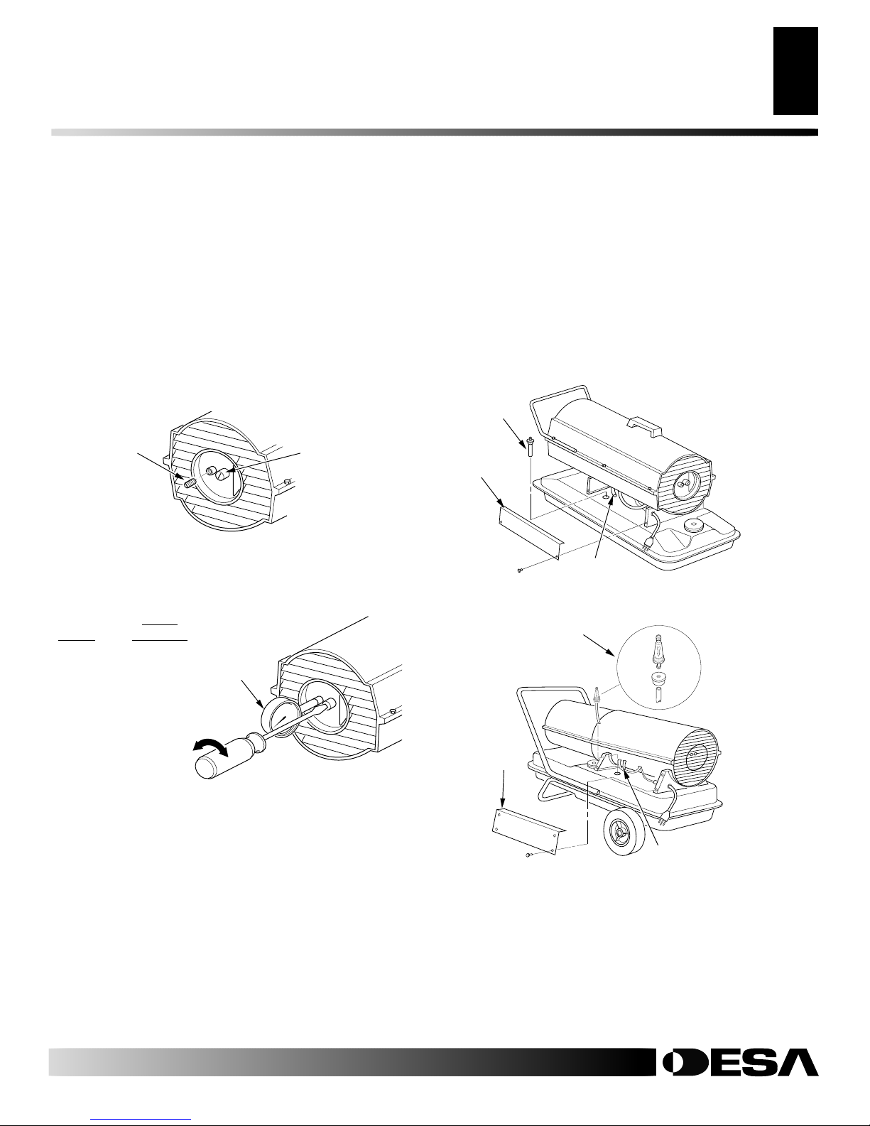
ASSEMBLY
(FOR 40, 55T, AND 70T MODELS ONLY)
These models are furnished with a nose cone guard. Nose cone
guard and mounting screws are found in the shipping carton.
Tools Needed
• 5/16" Nut Driver or Wrench
1. Place nose cone guard on top of upper shell flange. Make sure
nose cone guard is on hot air outlet end of heater.
2. Insert screws through nose cone guard and upper shell flange.
3. Tighten screws firmly.
Nose Cone
Screw
Guard
Fuel Tank
Side Cover
Ignition Control
Assembly
(assembly on inside
of side cover)
Figure 2 - 55T/70T Models
Hot Air
Outlet
Lower
Shell
Fuel Cap
Side Cover
Ignition Control
Assembly (assembly on
inside of side cover)
Figure 3 - 115T/165T Models
Upper Shell
Fan Guard
Power Cord
Air Filter
End Cover
Power Cord
Thermostat
Knob
Fuel
Tank
Hot Air
Outlet
Upper
Shell
Flange
Fuel
Cap
Figure 4 - Nose Cone Guard Assembly, 40/55T/70T Models Only
For more information, visit www.desatech.com
For more information, visit www.desatech.com
105536
ASSEMBLY
THEORY OF OPERATON
4
ASSEMBLY
Continued
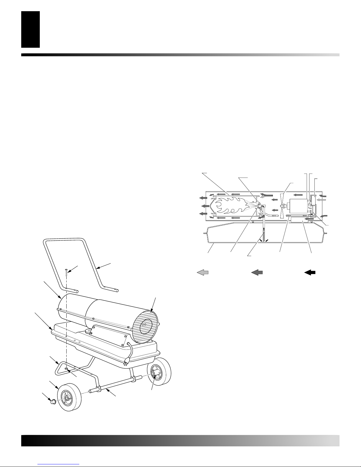
(FOR 115T AND 165T MODELS ONLY)
These models are furnished with wheels and a front handle. Some
models are furnished with a rear handle also. Wheels, handle(s), and
the mounting hardware is found in the shipping carton.
Tools Needed
• Medium Phillips Screwdriver
• 3/8" Open or Adjustable Wrench
• Hammer
1. Slide axle through wheel support frame. Install wheels on axle.
IMPORTANT:
support frame.
2. Place cap nuts on axle ends. Gently tap with hammer to secure.
3. Place heater on wheel support frame assembly. Make sure air
inlet end of heater is over wheels.
4. Place front handle on top of fuel tank flange. Insert screws
through handle(s), fuel tank flange and wheel support frame.
Attach nut finger tight after each screw is inserted.
5. Tighten all nuts firmly.
Place extended hub of wheel toward wheel
THEORY OF OPERATION
The Fuel System: The air pump forces air through the air line. The
air is then pushed through the nozzle. This air causes fuel to be lifted
from the tank. A fine mist of fuel is sprayed into the combustion
chamber.
The Air System: The motor turns the fan. The fan pushes air into
and around the combustion chamber. This air is heated and provides
a stream of clean, hot air.
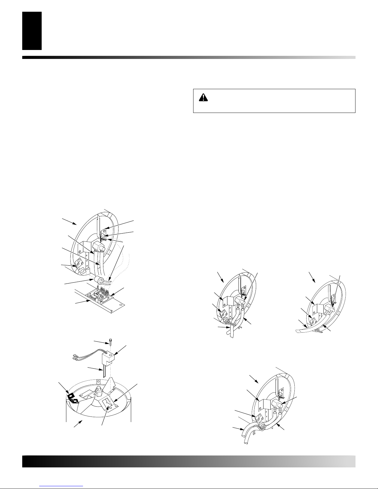
The Ignition System: The ignition control assembly provides
power to the ignitor. This ignites the fuel/air mixture in the combustion chamber.
The Flame-Out Control System: This system causes the heater to
shut down if the flame goes out.
Combustion Chamber
Ignitor
Clean
Heated
Air Out
Motor
Fan
Air Pump
Air Intake
Filter
Cool
Air In
Air
Output
Filter
Screw
Hot Air
Outlet
Fuel Tank
Flange
Wheel
Support
Frame
Wheel
Cap Nut
Figure 5 - Wheel and Handle Assembly, 115T/165T Models Only
Nut
Front
Handle
Air Inlet
Extended Hub
Axle
Fuel
Tank
Figure 6 - Cross Section Operational View
Nozzle
Air For Fuel
System
Fuel
Filter
Air For
Combustion
And Heating
Air Line
To Burner
Ignition Control
Assembly
Fuel
For more information, visit www.desatech.com
For more information, visit www.desatech.com
105536
FUELS
VENTILATION
OPERATION
5
5
FUELS
WARNING: Use only kerosene, #1/#2 diesel/fuel
oil, JET A or JP-8 fuels to avoid risk of fire or explosion. Never use gasoline, oil drained from crankcases, naphtha, paint thinners, alcohol or other highly
flammable fuels.
Use only kerosene, #1/#2 diesel/fuel oil, JET A or JP-8 fuels.
Heavier fuels such as No. 2 fuel oil or No. 2 diesel fuel may also be
used but will result in:
• noticeable odor
• additional fuel filter maintenance
• the need for nontoxic, anti-icer additives in very cold weather
Do not use fuels heavier than No. 2 grade or heavy oils such as oil
drained from crankcases. These heavy oils will not ignite properly
and will contaminate the heater.
IMPORTANT:
(yellow) storage container. Be sure storage container is clean. Foreign matter such as rust, dirt, or water will cause the ignition control
assembly to shut down heater. Foreign matter may also require
heater's fuel system to be frequently cleaned.
Use a KEROSENE ONLY (blue) or DIESEL ONLY
VENTILATION
WARNING: Provide a fresh air opening of at least
three square feet (2,800 square cm) for each 100,000
BTU/HR rating. Provide extra fresh air if more heaters
are being used. The minimum ventilation requirements must be followed to avoid risks associated
with carbon monoxide poisoning. Make certain these
requirements are met prior to operating heater.
OPERATION
IMPORTANT: Review and understand the warnings
in the
Safety Information
safely operate this heater. Follow all local ordinances
and codes when using this heater.
TO START HEATER
1. Follow all ventilation and safety information.
2. Fill fuel tank with kerosene, #1/#2 diesel/fuel oil, JET A or JP8 fuels.
3. Attach fuel cap.
4. For thermostat models 55T, 70T, 115T, and 165T, turn thermostat knob clockwise to the high position.
5. Plug heater’s power cord into approved, grounded, three-wire
extension cord. Extension cord must be at least six feet (1.8
meters) long.
Extension Cord Size Requirement
6 to 10 feet (1.8 to 3 meters) long, use 18 AWG (0.75 mm2)
rated cord
11 to 100 feet (3.3 to 30.5 meters) long, use 16 AWG (1.0
mm2) rated cord
101 to 200 feet (30.8 to 61 meters) long, use 14 AWG (1.5
mm2) rated cord
6. Plug extension cord into standard 120 volt/60 hertz, 3-prong
grounded outlet.
then heater will start.
7. For thermostat models 55T, 70T, 115T, and 165T, adjust thermostat knob to the desired setting.
affect the thermostat setting. This thermostat is a general-heating control. It is not intended for precise temperature control.
Adjust thermostat until heater cycles at the desired setting.
Note:
section. They are needed to
Ignitor will preheat for five seconds,
Note:
A cold heater may
Example:
• a two-car garage door (16 ft. [4.88 m] wide opening) raised four
inches (10.16 cm)
• a single-car garage door (9 ft. [2.74 m] wide opening) raised seven
inches (17.78 cm)
• two, thirty-inch (76.20 cm) windows raised twelve inches (30.48
cm)
105536
A 165 model heater requires one of the following:
For more information, visit www.desatech.com
For more information, visit www.desatech.com
TO STOP HEATER
Unplug extension cord from outlet.
TO RESTART HEATER
1. Unplug extension cord from outlet and wait 10 seconds. (W ait
two minutes if heater has been running.)
2. Repeat steps under To Start Heater.
STORING, TRANSPORTING, OR SHIPPING
PREVENTATIVE MAINTENANCE SCHEDULE
6
STORING, TRANSPORTING,
OR SHIPPING
Note:
If shipping, transport companies require fuel tanks to be
empty.
1. Drain fuel tank.
Note:
Some models have drain plug on underside of fuel tank.
If so, remove drain plug to drain all fuel. If heater does not
have drain plug, drain fuel through fuel cap opening. Be sure
all fuel is removed.
2. Replace drain plug if provided.
3. If any debris is noted in old fuel, add 1 or 2 quarts of clean
kerosene to tank, stir, and drain again. This will prevent excess debris from clogging filters during future use.
4. Replace fuel cap or drain plug. Properly dispose of old and
dirty fuel. Check with local automotive service stations that
recycle oil.
5. If storing, store heater in dry place. Make sure storage place is
free of dust and corrosive fumes.
IMPORTANT:
during next heating season. Using old fuel could damage heater.
Do not store kerosene over summer months for use
PREVENTATIVE
MAINTENANCE SCHEDULE
WARNING: To avoid risk of burn and electrical
shock, never attempt to service heater while it is
plugged in, operating, or hot.
Item How Often How To
Fuel tank Flush every 150-200 hours See Storing, Transporting, or
of operation or as needed Shipping, above
Air output and lint filters Replace every 500 hours of See Air Output, Air Intake,
operation or once a year and Lint Filters, page 8
Air intake filter Wash and dry with soap and See Air Output, Air Intake,
water every 500 hours of and Lint Filters, page 8
operation or replace as needed
Fuel filter Clean twice a heating season See Fuel Filter, page 9
or replace as needed
Ignitor None required
Fan blades Clean every season or See Fan, page 8
as needed
Motor Not required/permanently
lubricated
For more information, visit www.desatech.com
For more information, visit www.desatech.com
105536
TROUBLESHOOTING
WARNING: Never service heater while it is plugged
in, operating, or hot. Severe burns and electrical
shock can occur.
TROUBLESHOOTING
7
7
FAULT CONDITION
Motor does not start five seconds after heater
is plugged in
Motor starts and runs but heater does not
ignite
POSSIBLE CAUSE
1. No power to heater
2. Thermostat setting is too low
WARNING: High voltage!
3. Bad electrical connection between motor and ignition control assembly or ignition control assembly and power cord
4. Binding pump rotor
5. Defective ignition control assembly
6. Defective motor
1. No fuel in tank
2. Pump pressure incorrect
3. Dirty fuel filter
4. Obstruction in nozzle
5. Water in fuel tank
WARNING: High voltage!
6. Bad electrical connection between ignitor and ignition control assembly
7. Defective ignitor
8. Defective ignition control assembly
REMEDY
1. Check circuit breaker in electrical panel
2. Turn thermostat knob to a higher setting
3. Check all electrical connections. See
Wiring Diagrams, page 13
4. If fan does not turn freely, see Pump Ro-
tor, page 12
5. Replace ignition control assembly
6. Replace motor
1. Fill tank with kerosene
2. See Pump Pressure Adjustment, page 9
3. See Fuel Filter, page 9
4. See Nozzle Assembly, page 11
5. Drain and flush fuel tank with clean
kerosene. See Storing, Transporting, or
Shipping, page 6
6. Check electrical connections. See Wir-
ing Diagrams, page 13
7. Replace ignitor, see page 10
8. Replace ignition control assembly
Heater ignites but ignition control assembly
shuts heater off after a short period of time
For more information, visit www.desatech.com
For more information, visit www.desatech.com
105536
1. Pump pressure incorrect
2. Dirty air intake, air output, and/or lint
filter
3. Dirty fuel filter
4. Obstruction in nozzle
5. Photocell assembly not properly installed (not seeing the flame)
6. Dirty photocell lens
WARNING: High voltage!
7. Bad electrical connection between photocell and ignition control assembly
8. Defective photocell
9. Defective ignition control assembly
1. See Pump Pressure Adjustment, page 9
2. See Air Output, Air Intake, and Lint Fil-
ters, page 8
3. See Fuel Filter, page 9
4. See Nozzle Assembly, page 11
5. Make sure photocell boot is properly
seated in bracket
6. Clean photocell lens
7. Check electrical connections. See Wir-
ing Diagrams, page 13
8. Replace photocell
9. Replace ignition control assembly
SERVICE PROCEDURES
8
SERVICE PROCEDURES
WARNING: To avoid risk of burn and electrical
shock, never attempt to service heater while it is
plugged in, operating, or hot.
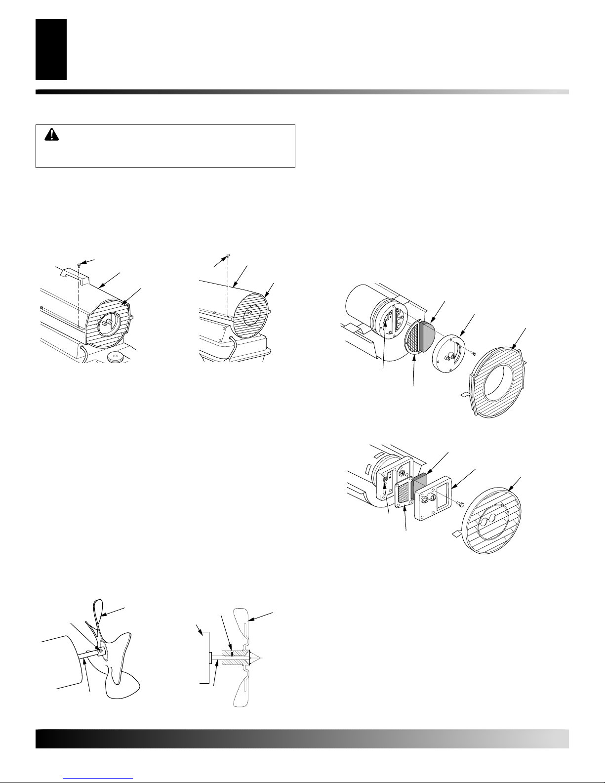
UPPER SHELL REMOVAL
1. Remove screws along each side of heater using 5/16" nutdriver. These screws attach upper and lower shells together.
See Figure 7 or 8.
2. Lift upper shell off.
3. Remove fan guard.
Screw
Upper Shell
Fan Guard
Figure 7 - Upper Shell Removal
(40/55T/70T Models Only)
Screw
Figure 8 - Upper Shell Removal
(115T/165T Models Only)
Upper Shell
Fan Guard
FAN
IMPORTANT:
motor from heater. The weight of the motor resting on the fan could
damage the fan pitch (see Figure 9).
1. Remove upper shell (see Figure 7 or 8).
2. Use 1/8" allen wrench to loosen setscrew which holds fan to
motor shaft.
3. Slip fan off motor shaft.
4. Clean fan using a soft cloth moistened with kerosene or solvent.
5. Dry fan thoroughly.
6. Replace fan on motor shaft. Place fan hub flush with end of
motor shaft (see Figure 10).
7. Place setscrew on flat of shaft. T ighten setscrew firmly (40-50
inch-pounds/4.5-5.6 n-m).
8. Replace fan guard and upper shell.
Remove fan from motor shaft before removing
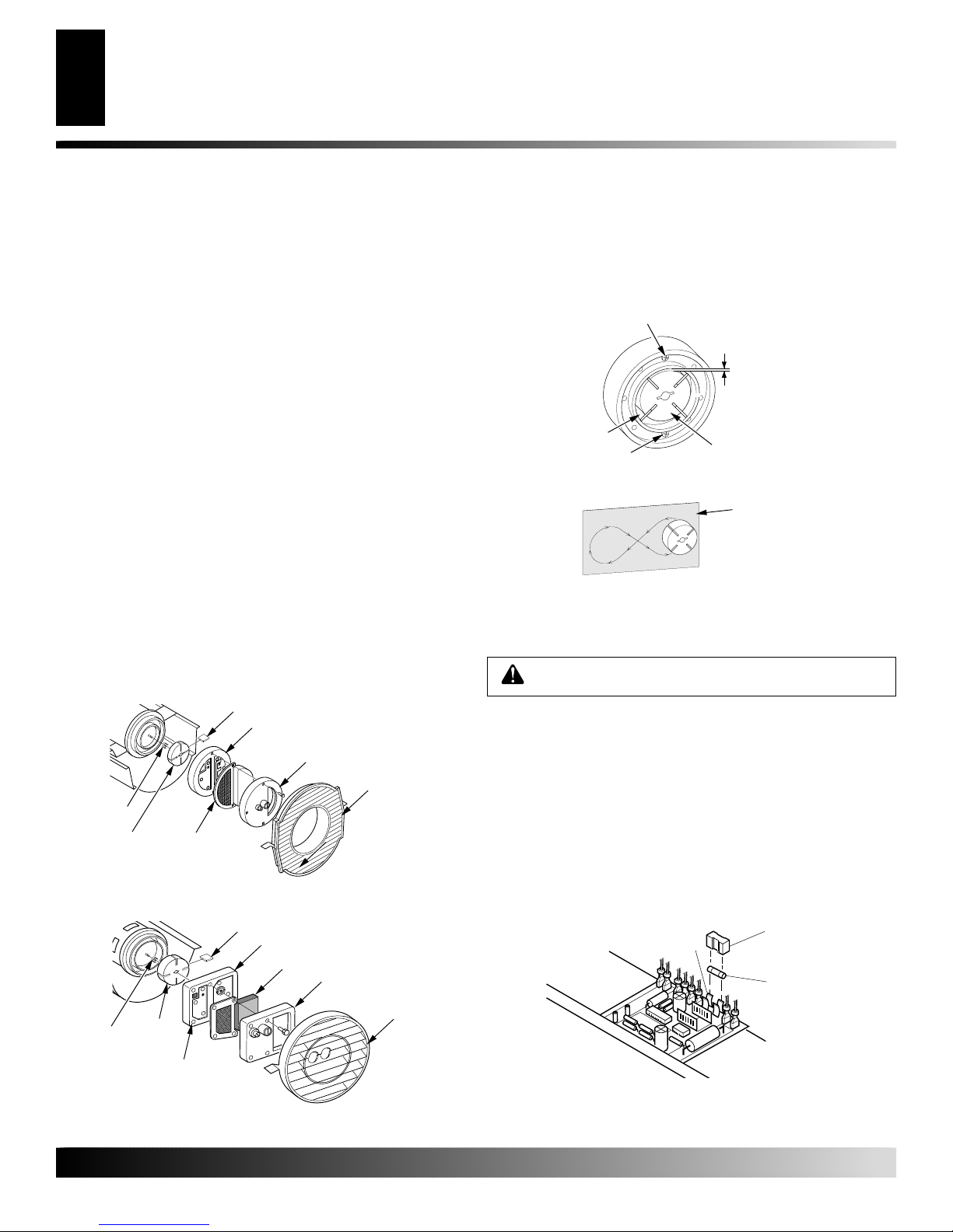
AIR OUTPUT, AIR INTAKE AND LINT FILTERS
1. Remove upper shell (see Figure 7 or 8).
2. Remove filter end cover screws using 5/16" nut-driver. See
Figure 11 or 12.
3. Remove filter end cover.
4. Replace air output and lint filters.
5. W ash or replace air intake filter (see Pre ventative Maintenance
Schedule, page 6).
6. Replace filter end cover.
7. Replace fan guard and upper shell.
IMPORTANT:
Figure 11 - Air Output, Air Intake, and Lint Filters, 40/55T/70T Models
Figure 12 - Air Output, Air Intake, and Lint Filters, 115T/165T Models
Do not oil filters.
Lint Filter
Air Output
Filter
Lint Filter
Air Output
Filter
Air Intake
Filter
Air Intake Filter
Filter End Cover
Filter End
Cover
Fan Guard
Fan Guard
Fan
Setscrew
Motor Shaft
Figure 9 - Fan, Motor Shaft,
and Setscrew Location
For more information, visit www.desatech.com
For more information, visit www.desatech.com
Setscrew
Motor
Motor Shaft
Figure 10 - Fan Cross Section
Fan
Flush
105536
SERVICE PROCEDURES
Continued
SERVICE PROCEDURES
9
9
PUMP PRESSURE ADJUSTMENT
1. Remove pressure gauge plug from filter end cover (see Figure 13).
2. Install accessory pressure gauge (part number HA1180).
3. Start heater (see Operation, page 5). Allow motor to reach
full speed.
4. Adjust pressure. T urn relief valve to right to increase pressure.
Turn relief valve to left to decrease pressure. See specifications correct pressure for each model (see Figure 14).
5. Remove pressure gauge. Replace pressure gauge plug in filter
end cover.
Pressure
Gauge
Plug
Figure 13 - Pressure Gauge Plug Removal
(40/55T/70T Models Shown)
Pump
Model Pressure
40 3.0 PSI
55T 3.4 PSI
70 T 4.7 PSI
115T 5.3 PSI
165T 5.6 PSI
Pressure
Gauge
Relief
Valve
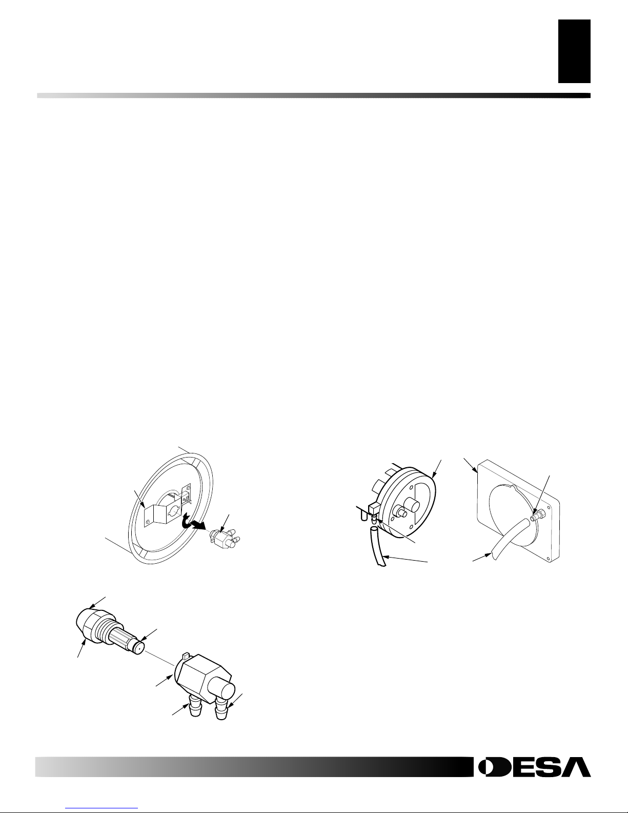
FUEL FILTER
1. Remove side cover screws using 5/16" nut-driver .
2. Remove side cover.
3. Pull upper fuel line off fuel filter neck (see Figure 15 or 16).
4. Carefully pry bushing, fuel filter, and lower fuel line (115T/
165T models only) out of fuel tank (see Figure 16).
5. Wash fuel filter with clean fuel and replace in tank.
6. Attach upper fuel line to fuel filter neck.
7. Replace side cover.
Fuel Filter
Side Cover
Upper Fuel
Line
Figure 15 - Fuel Filter Removal, 40/55T/70T Models
Fuel Filter, Bushing,
and Lower Fuel Line
Figure 14 - Adjusting Pump Pressure (40/55T/70T Models Shown)
For more information, visit www.desatech.com
For more information, visit www.desatech.com
105536
Side Cover
Upper Fuel Line
Figure 16 - Fuel Filter Removal, 115T/165T Models
SERVICE PROCEDURES
10
SERVICE PROCEDURES
Continued
IGNITOR
1. Remove upper shell and fan guard (See Upper Shell Removal,
page 8).
2. Remove fan (see page 8).
3. Remove 4 side cover screws with a 5/16" nut driver. Remove
side cover (see Figures 15 and 16).
4. Disconnect ignitor wires (yellow) from ignition control assembly (see Figure 17). Pull the ignitor wires up through
the hole in the lower shell.
5. Disconnect fuel line hose and air line hose. Remove photocell
from photocell bracket (see Figure 17).
6. Remove combustion chamber. Stand combustion chamber on
end with nozzle adapter bracket on top (see Figure 18).
7. Remove ignitor screw with a 1/4" nut driver . Carefully remove
ignitor from nozzle adapter bracket.
Combustion
Chamber
Air Line Hose
Fuel Line Hose
Photocell
Bracket
Photocell
Assembly
Side Cover
Figure 17 - Disconnecting Ignitor Wires from Ignition Control
Assembly
Ignitor Screw/Washer
Assembly
Ignitor Element
Photocell Bracket
Nozzle Adapter
Bracket
Ignitor
Ignitor Wire
(Yellow)
Ignition
Control
Assembly
Ignitor
Nozzle Adapter
Bracket
CAUTION: Do not bend or strike ignitor element.
Handle with care.
8. Carefully remove replacement ignitor from styrofoam packing.
9. Carefully guide ignitor into opening in nozzle adapter bracket.
Do not strike ignitor element. Attach ignitor to nozzle adapter
bracket with screw using a 1/4" nut driver (see Figure 18). Torque
8 to 15 in. lbs. Do not over torque.
10. Replace combustion chamber.
11. Route the ignitor wires back down through the hole in the
lower shell. Connect wires to the ignition control assembly
(see Figure 17).
12. Replace side cover (see Figures 15 and 16, page 9).
13. Connect and route fuel line hose and air line hose to nozzle
adapter assembly. See Fuel and Air Line Replacement and
Proper Routing, page 11.
14. Replace photocell in photocell bracket. Route wires as
shown in Figure 19, 20, or 21.
15. Replace fan (see Fan, page 8).
16. Replace fan guard and upper shell (see Upper Shell Removal,
page 8).
Combustion
Chamber
Burner
Strap
Photocell
Bracket
Air Line
Hose
Figure 19 - Removing Air and
Fuel Line Hoses, (40/55T/70T
Models Only)
Combustion
Chamber
Burner
Strap
Photocell
Bracket
Nozzle/
Adapter
Assembly
Fuel Line
Hose
Combustion
Chamber
Burner
Strap
Photocell
Bracket
Air Line
Hose
Figure 20 - Removing Air and
Fuel Line Hoses, (115T Model
Only)
Nozzle/
Adapter
Assembly
Nozzle/
Adapter
Assembly
Fuel Line
Hose
Combustion
Chamber
Figure 18 - Ignitor Replacement
Nozzle Adapter
Bracket Opening
For more information, visit www.desatech.com
For more information, visit www.desatech.com
Air Line
Hose
Figure 21 - Removing Air and Fuel Line Hoses (165T Model Only)
Fuel Line
Hose
105536
SERVICE PROCEDURES
Continued
SERVICE PROCEDURES
11
11
NOZZLE ASSEMBLY
1. Remove upper shell (see Upper Shell Removal, page 8).
2. Remove fan (see Fan, page 8).
3. Remove fuel and air line hoses from nozzle assembly (see Figure 19, 20, or 21, page 10).
4. Turn nozzle assembly 1/4 turn to left and pull toward motor to
remove (see Figure 22).
5. Place plastic hex-body into vise and lightly tighten.
6. Carefully remove nozzle from the nozzle adapter using 5/8"
socket wrench. See Figure 23.
7. Blow compressed air through face of nozzle. This will free
any dirt in nozzle area.
8. Inspect nozzle sleeve for damage.
9. Replace nozzle into nozzle adapter until nozzle seats. T ighten
1/3 turn more using 5/8" socket wrench (40-45 inch-pounds).
See Figure 23.
10. Attach nozzle assembly to burner strap (see Figure 22).
11. Attach fuel and airline hoses to nozzle adapter assembly. See
Fuel and Air Line Replacement and Proper Routing.
12. Replace fan (see Fan, page 8).
13. Replace fan guard and upper shell (see Upper Shell Removal,
page 8).
FUEL AND AIR LINE REPLACEMENT AND
PROPER ROUTING
1. Remove upper shell (see Upper Shell Removal, page 8).
2. Remove side cover screws using 5/16" nut driver (see Figure 15
or 16, page 9).
3. Remove side cover.
4. Inspect fuel and air line hoses for cracks and/or holes. If fuel
line hose is damaged, disconnect from nozzle adapter (see Figure 19, 20, or 21, page 10) and from fuel filter (see Fuel Filter,
page 9). If air line hose is damaged, disconnect from nozzle
adapter (see Figure 19, 20, or 21, page 10) and from barb fitting
on pump end cover (see Figure 24).
5. Install new air and/or fuel line. Attach one end of air line hose to
barb fitting on pump end cover (see Figure 24) and the other
end to nozzle adapter (see Figure 19, 20, or 21, page 10). Attach
one end of fuel line hose to fuel filter (see Fuel Filter, page 9)
and the other end to nozzle adapter (see Figure 19, 20, or 21,
page 10).
Note:
Route hoses as shown in Figure 19, 20, or 21, page 10,
according to model. Hoses are not to touch photocell bracket.
6. Replace side cover.
7. Replace upper shell and fan guard (see Upper Shell Removal,
page 8).
Burner Strap
Nozzle
Assembly
Figure 22 - Removing Nozzle Assembly, All Models
Nozzle Face
Nozzle
Sleeve
Nozzle
Nozzle Adapter
Air Line
Fitting
Figure 23 - Nozzle and Nozzle Adapter, All Models
Fuel Line
Fitting
Pump End Cover
Barb
Fitting
Air Hose
40/55T/70T
Models
Figure 24 - Air Hose to Barb Fitting
Barb Fitting
115T/165T
Models
For more information, visit www.desatech.com
For more information, visit www.desatech.com
105536
SERVICE PROCEDURES
12
SERVICE PROCEDURES
Continued
PUMP ROTOR
(Procedure if Rotor is Binding)
1. Remove upper shell (see Upper Shell Removal, page 8).
2. Remove filter end cover screws using 5/16" nut-driver (see
Figure 25 or 26).
3. Remove filter end cover and air filters.
4. Remove pump plate screws using 5/16" nut-driver.
5. Remove pump plate.
6. Remove rotor, insert, and blades.
7. Check for debris in pump. If debris is found, blow out with
compressed air.
8. Install insert and rotor.
9. Check gap on rotor. Adjust to .003"/.004" (.076-.101 mm) if
needed (see Figure 27).
Note:
Rotate Rotor one full turn to insure the gap is .003"/.004"
(.076-.101 mm) at tightest position. Adjust if needed.
10. Install blades, pump plate, air filters, and filter end cover.
11. Replace fan guard and upper shell (see Upper Shell Removal,
page 8).
12. Adjust pump pressure (see Pump Pressure Adjustment, page 9).
Note:
If rotor is still binding, proceed as follows.
13. Perform steps 1 thru 6.
Blade
Pump Plate
Air Intake Filter
Filter End Cover
Fan Guard
Insert
Rotor
OTOR-Domestic
Figure 25 - Rotor Location, 40/55T/70T Models
Air Output
Filter
PFA/P 056B
14. Place fine grade sandpaper (600 grit) on flat surface. Sand rotor
lightly in “figure 8” motion four times (see Figure 28).
15. Reinstall insert and rotor.
16. Perform steps 10 thru 12.
Gap Adjusting Screw
.003"/.004"
(.076-.101 mm)
Gap Measured
With Feeler
Blade
Gap Adjusting Screw
Figure 27 - Gap Adjusting Screw Locations
Figure 28 - Sanding Rotor
Gauge
Rotor
Sandpaper
IGNITION CONTROL ASSEMBLY
WARNING: High Voltage!
1. Unplug heater .
2. Remove side cover screws (4) using 5/16" nut-driver to expose ignition control assembly (see Figure 15 or 16, page 9).
3. Remove fuse cover (see Figure 29).
4. Remove fuse from fuse clips (see Figure 29).
5. Replace fuse with fuse of the same type and rating (GMA-10).
Do not substitute a fuse with a higher current rating.
6. Replace fuse cover (see Figure 29).
7. Replace side cover (see Figure 15 or 16, page 9).
Blade
Pump Plate
Air Intake Filter
Insert
Figure 26 - Rotor Location, 115T/165T Models
Rotor
Air Output
OR-Domestic PFA/P 059A
Filter
For more information, visit www.desatech.com
For more information, visit www.desatech.com
Filter End Cover
Fan
Guard
Figure 29 - Replacing Fuse
Fuse
Clips
Fuse
Cover
Fuse
105536
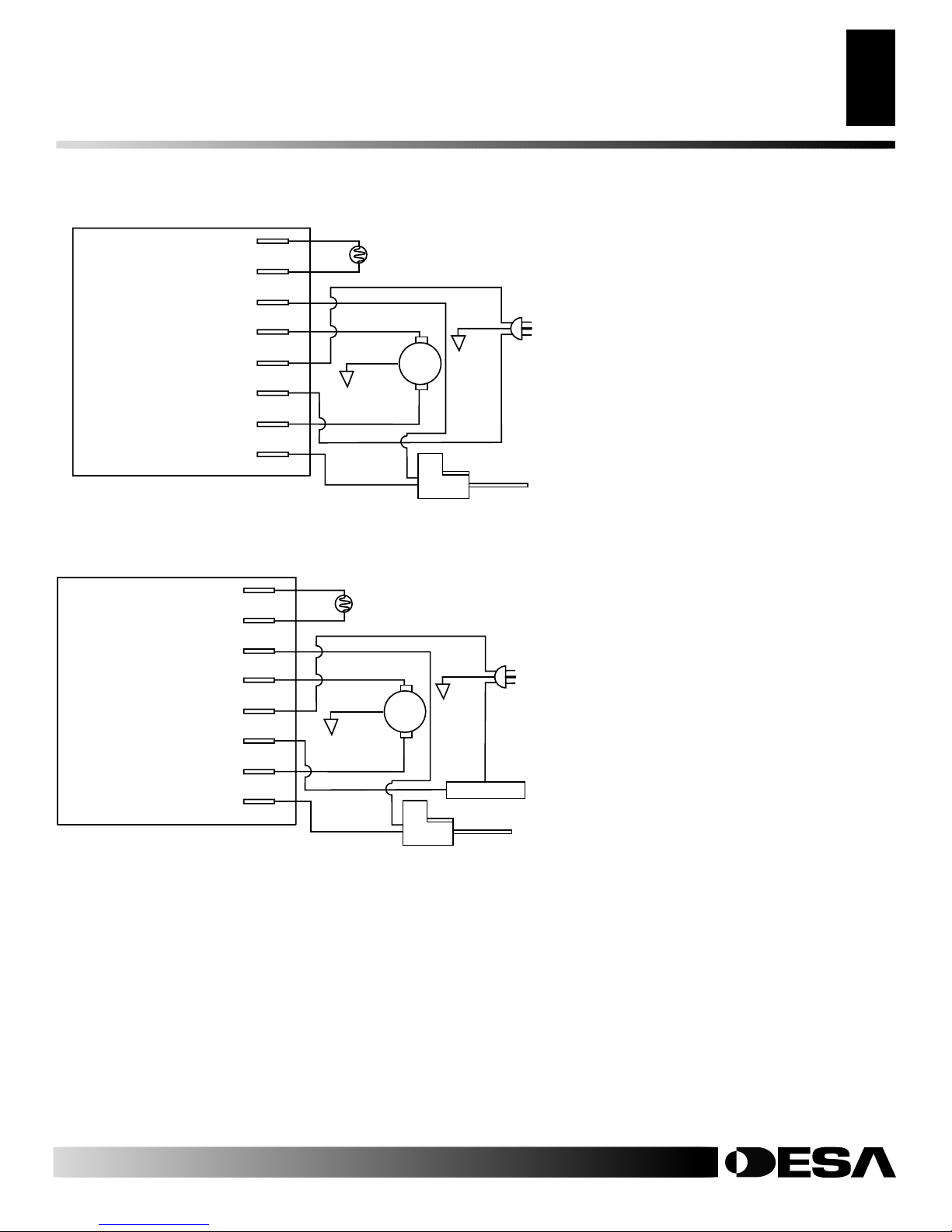
WIRING DIAGRAMS
WIRING DIAGRAMS
13
13
Photocell
Photocell
Ignitor
Motor Return
AC Neutral (L2)
120V (L1)
Ignition Control Assembly
Figure 30 - Wiring Diagram for 40 Models
Motor Return
AC Neutral (L2)
Motor
Ignitor
Photocell
Photocell
Ignitor
Blue
Blue
Blue
Blue
White
Red
Black
Yellow
White
Green
Photocell
Green
Photocell
White
Motor
White
Motor
Ignitor
Green
Yellow
Green
Power Plug
120V/60Hz
Power Plug
120V/60Hz
120V (L1)
Ignition Control Assembly
Figure 31 - Wiring Diagram for 55T/70T/115T/165T Thermostat Models
105536
Motor
Ignitor
For more information, visit www.desatech.com
For more information, visit www.desatech.com
Red
Black
Y ellow
Yellow
Black
Thermostat
Ignitor

SPECIFICATIONS
14
SPECIFICATIONS
Model Size 40 55T 70T 115T 165T
Output Rating (Btu/Hr) 40,000 55,000 70,000 115,000 165,000
Fuel Use only kerosene, #1/#2 diesel/fuel oil, JET A or JP-8 fuels*
Fuel Tank Capacity
(U.S. Gal./Liters) 3/11.3 5/18.9 5/18.9 9/34 13.5/51
Fuel Consumption
(Gal. Per Hr/Liters Per Hr) .3/1.14 .44/1.67 .52/1.97 .85/3.00 1.2/4.54
Pump Pressure (psi) 3.0 3.4 4.7 5.3 5.6
Electric Requirements 120 V/60 HZ (Same All Models)
Amperage (Normal Run) 2.0 2.0 2.8 3.6 3.6
Motor RPM 1725 1725 3440 3440 3440
Hot Air Output (CFM) 170 180 360 490 575
Shipping Weight 32 35 35 53 63
(Approximate Pounds)
Heater Weight without Fuel 28 30 30 45 53
(Approximate Pounds)
* Use of #2 diesel & fuel oil will result in noticeable odor and could require additional fuel filter maintenance. Use in extreme cold
temperatures may require nontoxic anti-icer additives.
For more information, visit www.desatech.com
For more information, visit www.desatech.com
105536
 Loading...