

Page 1
Save this manual for future reference.
For more information, visit www.desatech.com
WARNING: If the information in this manual is not followed exactly, a fire or explosion may result causing
property damage, personal injury or loss of life.
— Do not store or use gasoline or other flammable
vapors and liquids in the vicinity of this or any other
appliance.
— WHAT TO DO IF YOU SMELL GAS
• Do not try to light any appliance.
• Do not touch any electrical switch; do not use any
phone in your building.
• Immediately call your gas supplier from a neighbor’s
phone. Follow the gas supplier’s instructions.
• If you cannot reach your gas supplier, call the fire
department.
— Installation and service must be performed by a quali-
fied installer, service agency or the gas supplier.
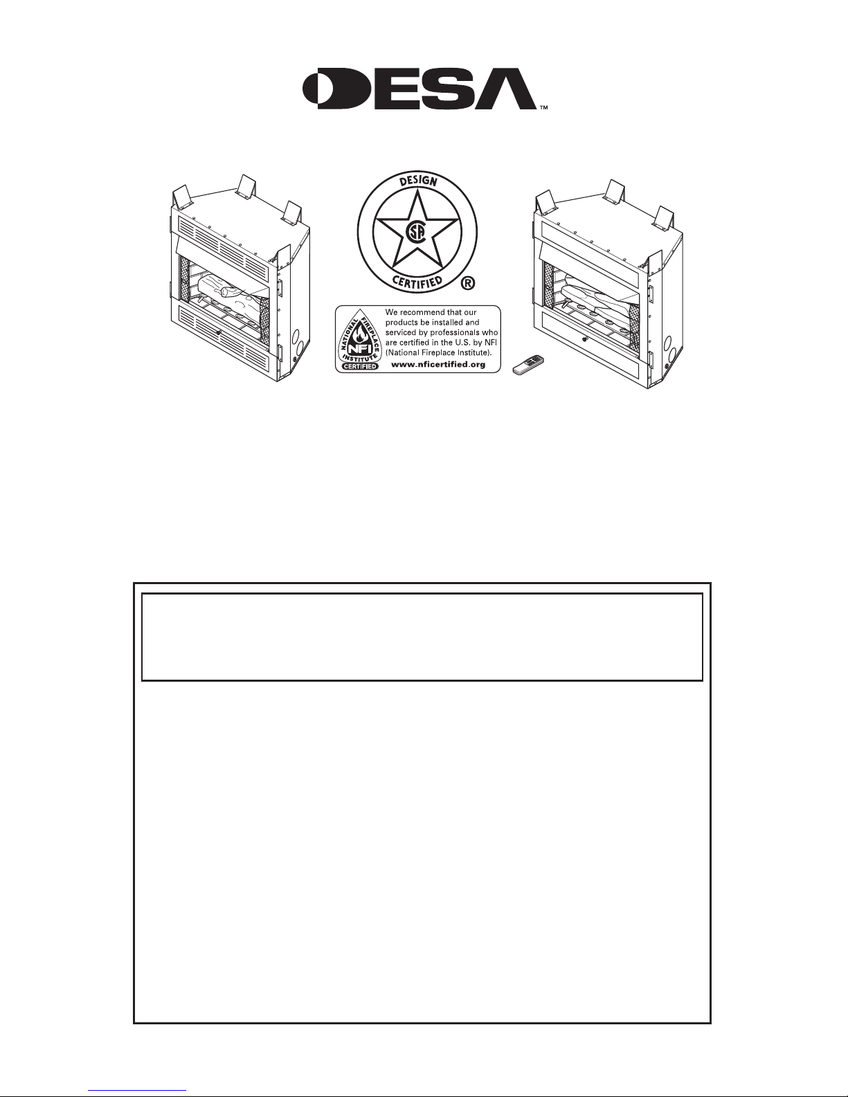
UNVENTED (VENT-FREE) FIREPLACE
OWNER’S OPERATION AND INSTALLATION MANUAL
MANUALLY CONTROLLED
MODELS
NATURAL GAS
(V)L32(HN, LHN)
(V)L36(EN, LEN)
PROPANE/LP GAS
(V)L32(HP, LHP)
(V)L36(EP, LEP)
REMOTE CONTROL READY
MODELS
NATURAL GAS
(V)L36(ZNR, LZNR)
(V)L42(ZNR, LZNR)
PROPANE/LP GAS
(V)L36(ZPR, LZPR)
(V)L42(ZPR, LZPR)
Page 2
www.desatech.com
115254-01A
2
WARNING: Improper installation, adjustment, alteration, service or maintenance can cause injury or property damage. Refer to this manual for correct installation
and operational procedures. For assistance or additional information consult a qualified installer, service
agency or the gas supplier.
WARNING: FOR USE ONLY WITH A LISTED DECORATIVE TYPE UNVENTED ROOM HEATER. DO NOT BUILD
A WOOD FIRE.
This appliance may be installed in an aftermarket,* permanently located, manufactured (mobile) home, where
not prohibited by local codes.
This appliance is only for use with the type of gas indicated on the rating plate. This appliance is not convertible for use with other gases.
* Aftermarket: Completion of sale, not for purpose of resale, from the manufacturer
State of Massachusetts: The installation must be made by a licensed plumber or gas fitter in the
Commonwealth of Massachusetts.
Sellers of unvented propane or natural gas-fired supplemental room heaters shall provide to each
purchaser a copy of 527 CMR 30 upon sale of the unit.
Vent-free gas products are prohibited for bedroom and bathroom installation in the Common
-
wealth of Massachusetts.
TABLE OF CONTENTS
Safety Information ............................................... 3
Local Codes ........................................................ 4
Product Features ................................................. 4
Locating Firebox .................................................. 5
Product Specifications ......................................... 5
Air For Combustion and Ventilation ..................... 7
Installation ........................................................... 9
Operating Fireplace ........................................... 21
Inspecting Burners ............................................ 27
Cleaning and Maintenance ................................ 28
Troubleshooting .................................................
29
Specifications ....................................................
33
Wiring Diagram .................................................. 33
Service Hints ..................................................... 34
Technical Service ..............................................
34
Replacement Parts ............................................ 34
Accessories ....................................................... 35
Illustrated Parts Breakdown and Pars List ........ 36
Warranty Information ............................ Back Page
Page 3
www.desatech.com
115254-01A 3
SAFETY INFORMATION
WARNING: This product contains and/or generates chemicals
known to the state of California
to cause cancer or birth defects
or other reproductive harm.
IMPORTANT: Read this owner’s
manual carefully and completely
before trying to assemble,
operate or service this heater.
Improper use of this heater can
cause serious injury or death
from burns, fire, explosion,
electrical shock and carbon
monoxide poisoning.
DANGER: Carbon monoxide
poisoning may lead to death!
Carbon Monoxide Poisoning: Early signs of
carbon monoxide poisoning resemble the flu, with
headaches, dizziness or nausea. If you have these
signs, the heater may not be working properly. Get
fresh air at once! Have heater serviced. Some
people are more affected by carbon monoxide than
others. These include pregnant women, people with
heart or lung disease or anemia, those under the
influence of alcohol and those at high altitudes.
Natural and Propane/LP Gas: Natural and pro-
pane/LP gases are odorless. An odor-making agent
is added to the gas. The odor helps you detect a gas
leak. However, the odor added to the gas can fade.
Gas may be present even though no odor exists.
Make certain you read and understand all warnings.
Keep this manual for reference. It is your guide to
safe and proper operation of this heater.
WARNING: Any change to
this heater or its controls can
be dangerous.
WARNING: Do not use a
blower insert, heat exchanger
insert or other accessory not ap
-
proved for use with this heater.
WARNING: Do not allow fans
to blow directly into the fireplace.
Avoid any drafts that alter burner
flame patterns. Ceiling fans can
create drafts that alter burner
flame patterns. Altered burner
patterns can cause sooting.
Due to high temperatures, the
appliance should be located out
of traffic and away from furniture
and draperies.
Do not place clothing or other
flammable material on or near
the appliance. Never place any
objects on the heater.
Fireplace front and screen be
-
come very hot when running fire
place. Keep children and adults
away from hot surfaces to avoid
burns or clothing ignition. Fireplace will remain hot for a time
after shutdown. Allow surfaces
to cool before touching.
Carefully supervise young children when they are in the room
with fireplace. When using the
optional hand-held remote accessory, keep selector switch
in the OFF position to prevent
children from turning on burners
with remote.
You must operate this fireplace
with the fireplace screen and
hood in place. Make sure fireplace screen and hood are in
place before running heater.
Keep the appliance area clear
and free from combustible materials, gasoline and other flammable vapors and liquids.
Page 4

www.desatech.com
115254-01A
4
PRODUCT FEATURES
OPERATION
This firebox is designed for use with approved ANSI
Z21.11.2 decorative type unvented room heaters.
(Physical size limitations apply. Refer to minimum
firebox requirements supplied with log heater.) It
requires no outside venting or chimney making in
stallation easy and inexpensive. When used without
the blower, the firebox requires no electricity making it ideal for emergency backup heat.
BLOWER ACCESSORY
The circulating models will accept a rotary type
fan (model BK) accessory. The blower circulates
heated air from the firebox into the room. Use of
blower is optional.
REFRACTORY BRICK LINER
Your firebox may feature a concrete refractory
brick liner. As with all concrete liners, this liner
may develop slight cracks when exposed to heat.
These cracks will not affect the performance of
the fireplace or vent-free gas logs.
1.
This appliance is only for use with the type of
gas indicated on the rating plate. This appliance
is not convertible for use with other gases.
2. Do not place propane/LP supply tank(s) inside any structure. Locate propane/LP supply
tank(s) outdoors (propane/LP units only).
3. If you smell gas
• shut off gas supply
• do not try to light any appliance
• do not touch any electrical switch; do not use
any phone in your building
• immediately call your gas supplier from
a neighborʼs phone . Follow the ga s
supplierʼs instructions
• if you cannot reach your gas supplier, call
the fire department
4. This fireplace shall not be installed in a bed
-
room or bathroom.
5. Do not use this fireplace as a wood-burning
fireplace. Use only the logs provided with
the fireplace.
6. Do not add extra logs or ornaments such as
pine cones, vermiculite or rock wool. Using
these added items can cause sooting. Do not
add lava rock around base. Rock and debris
could fall into the control area of fireplace.
7. To prevent the creation of soot, follow the instruc
-
tions in Cleaning and Maintenance, page 28.
8. Before using furniture polish, wax, carpet
cleaner or similar products, turn heater off. If
heated, the vapors from these products may
create a white powder residue within burner
box or on adjacent walls or furniture.
9. This fireplace needs fresh air ventilation to run
properly. This fireplace has an Oxygen Deple
tion Sensing (ODS) safety shutoff system. The
ODS shuts down the fireplace if enough fresh
air is not available. See Air for Combustion
and Ventilation, page 7. If fireplace keeps
shutting off, see Troubleshooting, page 29.
10. Do not run fireplace
• where flammable liquids or vapors are used
or stored
• under dusty conditions
11. Do not use this fireplace to cook food or burn
paper or other objects.
12. Do not use fireplace if any part has been exposed
to or under water. Immediately call a qualified
service technician to inspect the fireplace and to
replace any part of the control system and any
gas control which has been under water.
SAFETY INFORMATION
Continued
13. Do not operate fireplace if any log is broken.
Do not operate fireplace if a log is chipped
(dime-sized or larger).
14. Turn fireplace off and let cool before servicing.
Only a qualified service person should service
and repair fireplace.
15. Operating fireplace above elevations of 4,500
feet could cause pilot outage.
16.
To prevent performance problems in propane/LP
units, do not use propane/LP fuel tanks of less
than 100 lbs. capacity (propane/LP units only).
17.
Provide adequate clearances around air
openings.
LOCAL CODES
Install and use fireplace with care. Follow all local
codes. In the absence of local codes, use the lat
est edition of The National Fuel Gas Code ANSI
Z223.1/NFPA 54*.
*Available from:
American National Standards Institute, Inc.
1430 Broadway
New York, NY 10018
National Fire Protection Association, Inc.
Batterymarch Park
Quincy, MA 02269
Note: Where listed vented decorative logs are
required, thermostat operation is not permitted.
Page 5
www.desatech.com
115254-01A 5
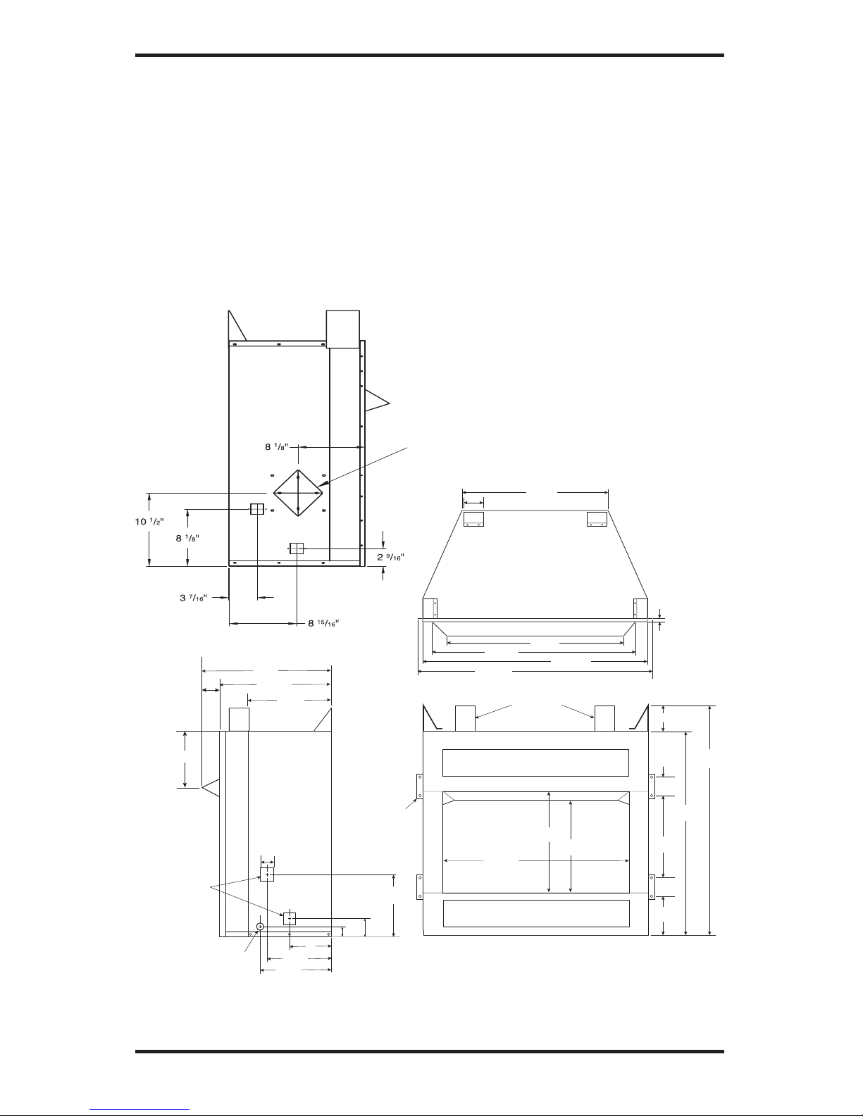
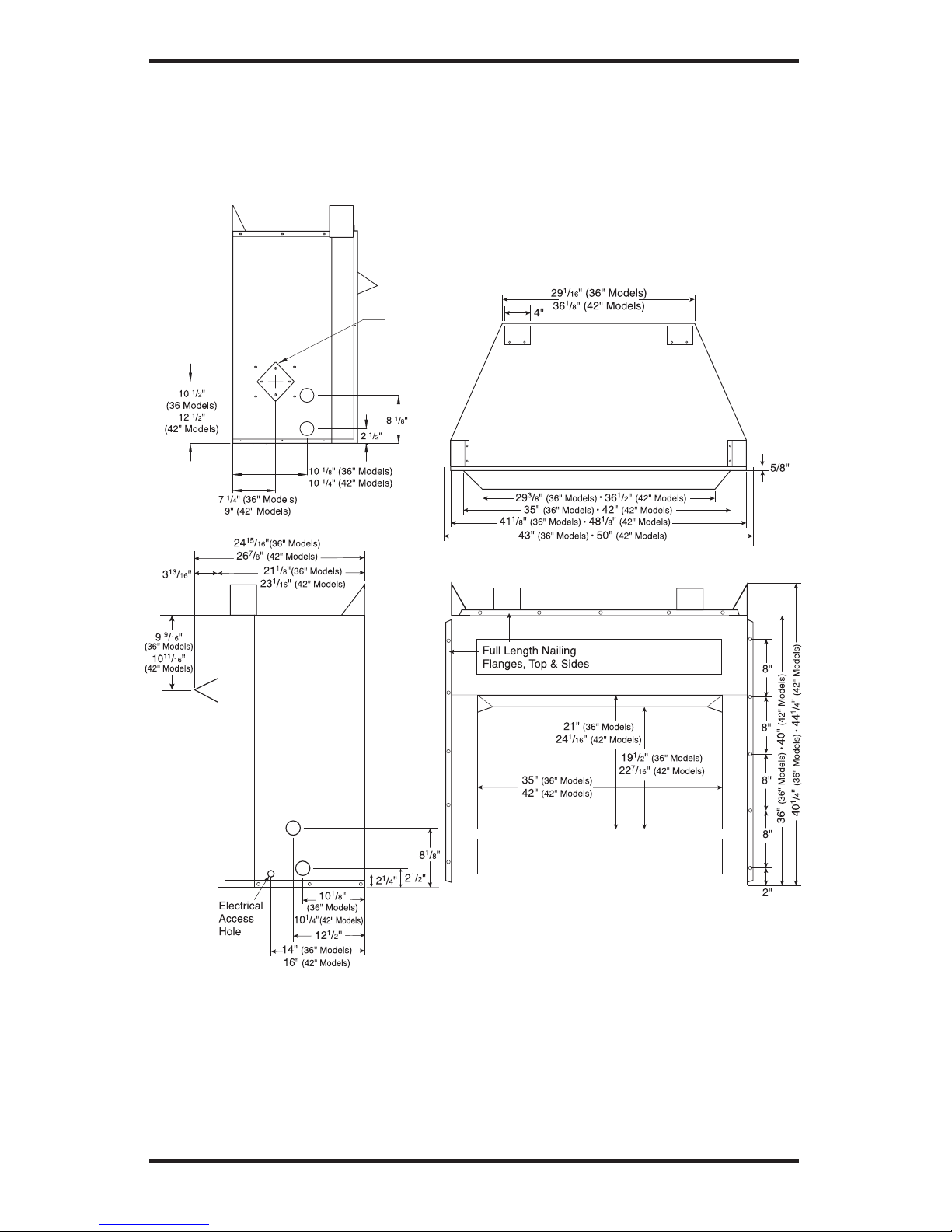
PRODUCT SPECIFICATIONS
32" MODELS
251/8"
291/2"
347/16"
363/8"
Standoffs
221/2"
4"
291/2"
163/4"
187/16"
321/4"
361/2"
1415/16"
65/16"
33/8"
6"
815/16"
93/4"
12 1/4"
19 1/2"
16 11/16"
21/4"
19/16"
29/16"
81/8"
2 13/16"
8 5/8"
41/4"
31/2"
Built-In
Side
Nailing
Flanges
Square
Gas Line
Access
Holes
Electrical
Access Hole
5/8"
Figure 1 - Firebox Dimensions (32" Models)
Right Side
View
Firebox Top View
Front View
Outside Air
Kit Location
(Optional)
Left Side
View with
Air Kit
LOCATING FIREBOX
PLANNING
Plan where you will install the firebox. This will
save time and money later when you install the fire
-
box. Before installation, consider the following:
1. Where the firebox will be located. Allow for
wall and ceiling clearances (see
Installation
Clearances, page 9).
2. Everything needed to complete installation.
3. These models CANNOT be installed in a
bedroom unless the maximum Btu rating
of the installed vent-free log set is less than
10,000 Btu/hr.
4. Proper air for combustion and ventilation
(page 7).
Page 6
www.desatech.com
115254-01A
6
PRODUCT SPECIFICATIONS
Continued
Figure 2 - Firebox Dimensions (36" and 42" Models)
36" AND 42" MODELS
Note: If only one dimension is shown, the dimension is the same for both 36" and 42" models.
Firebox Top View
Front View
Right
Side
View
Outside Air
Kit Location
(Optional)
Left Side
View with
Air Kit
Page 7
www.desatech.com
115254-01A 7
AIR FOR COMBUSTION
AND VENTILATION
WARNING: This firebox shall
not be installed in a confined
space or unusually tight construction unless provisions are
provided for adequate combus
tion and ventilation air. Read the
following instructions to insure
proper fresh air for this and
other fuel-burning appliances
in your home.
Todayʼs homes are built more energy efficient
than ever. New materials, increased insulation and
new construction methods help reduce heat loss
in homes. Home owners weather strip and caulk
around windows and doors to keep the cold air out
and the warm air in. During heating months, home
owners want their homes as airtight as possible.
While it is good to make your home energy effi
cient, your home needs to breathe. Fresh air must
enter your home. All fuel-burning appliances need
fresh air for proper combustion and ventilation.
Exhaust fans, fireboxes, clothes dryers and fuel
burning appliances draw air from the house to
operate. You must provide adequate fresh air for
these appliances. This will insure proper venting
of vented fuel-burning appliances.
PROVIDING ADEQUATE
VENTILATION
The following are excerpts from National Fuel Gas
Code, ANSI Z223.1/NFPA 54, Section 5.3, Air for
Combustion and Ventilation.
All spaces in homes fall into one of the three fol
lowing ventilation classifications:
1. Unusually Tight Construction
2. Unconfined Space
3. Confined Space
The information on page 7 through 9 will help
you classify your space and provide adequate
ventilation.
Unusually Tight Construction
The air that leaks around doors and windows
may provide enough fresh air for combustion and
ventilation. However, in buildings of unusually
tight construction, you must provide additional
fresh air.
Unusually tight construction is defined as
construction where:
a. walls and ceilings exposed to the out
side atmosphere have a continuous
water vapor retarder with a rating of
one perm (6 x 10
-11
kg per pa-sec-m2) or
less with openings gasketed or sealed
and
b. weather stripping has been added on
openable windows and doors
and
c. caulking or sealants are applied to
areas such as joints around window
and door frames, between sole plates
and floors, between wall-ceiling joints,
between wall panels, at penetrations
for plumbing, electrical and gas lines
and at other openings.
If your home meets all of the three criteria
above, you must provide additional fresh
air. See Ventilation Air From Outdoors
,
page 9.
If your home does not meet all of the
three
criteria above, proceed to Determining
Fresh-Air Flow for Firebox Location.
Confined and Unconfined Space
The National Fuel Gas Code, ANSI Z223.1/NFPA
54 defines a confined space as a space whose
volume is less than 50 cubic feet per 1,000 Btu
per hour (4.8 m
3
per kw) of the aggregate input
rating of all appliances installed in that space and
an unconfined space as a space whose volume is
not less than 50 cubic feet per 1,000 Btu per hour
(4.8 m
3
per kw) of the aggregate input rating of
all appliances installed in that space. Rooms com
municating directly with the space in which the
appliances are installed*, through openings not
furnished with doors, are considered a part of the
unconfined space.
* Adjoining rooms are communicating only if
there are doorless passageways or ventilation grills
between them.
DETERMINING FRESH-AIR FLOW
FOR HEATER LOCATION
Determining if You Have a Confined or
Unconfined Space
Use this work sheet to determine if you have a
confined or unconfined space.
Space: Includes the room in which you will
install heater plus any adjoining rooms with door
less passageways or ventilation grills between
the rooms.
Page 8
www.desatech.com
115254-01A
8
AIR FOR COMBUSTION
AND VENTILATION
Continued
1. Determine the volume of the space (length x
width x height).
Length x Width x Height = ________ cu. ft.
(volume of space)
Example: Space size 22 ft. (length) x 18 ft.
(width) x 8 ft. (ceiling height) = 3168 cu. ft.
(volume of space)
If additional ventilation to adjoining room is
supplied with grills or openings, add the volume
of these rooms to the total volume of the space.
2. Multiply the space volume by 20 to determine
the maximum Btu/Hr the space can support.
_______(volume of space) x 20 = (Maximum
Btu/Hr the space can support)
Example: 3168 cu. ft. (volume of space) x 20 =
63,360 (maximum Btu/Hr the space can support)
3. Add the Btu/Hr of all fuel burning appliances
in the space.
Vent-free heater
__________ Btu/Hr
Gas water heater*
__________ Btu/Hr
Gas furnace
__________ Btu/Hr
Vented gas heater
__________ Btu/Hr
Gas fireplace logs
__________ Btu/Hr
Other gas appliances* + ________
Btu/Hr
Total = ________
Btu/Hr
* Do not include direct-vent gas appliances.
Direct-vent draws combustion air from the
outdoors and vents to the outdoors.
Example:
Gas water heater
__________ Btu/Hr
Vent-free heater + ________
Btu/Hr
Total = ________
Btu/Hr
4. Compare the maximum Btu/Hr the space can
support with the actual amount of Btu/Hr used.
__________ Btu/Hr (maximum the space
can support)
__________ Btu/Hr (actual amount of
Btu/Hr used)
Example: 63,360 Btu/Hr (maximum
the space can support)
79,000 Btu/Hr (actual amount
of Btu/Hr used)
The space in the above example is a confined
space because the actual Btu/Hr used is more than
the maximum Btu/Hr the space can support. You
must provide additional fresh air. Your options
are as follows:
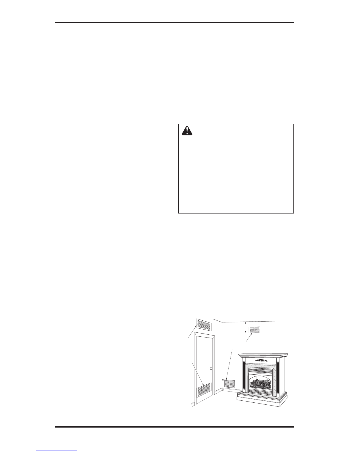
VENTILATION AIR
Ventilation Air From Inside Building
This fresh air would come from an adjoining un
confined space. When ventilating to an adjoining
unconfined space, you must provide two perma
nent openings: one within 12" of the ceiling and
one within 12" of the floor on the wall connecting
the two spaces (see options 1 and 2, Figure 4). You
can also remove door into adjoining room (see
option 3, Figure 3). Follow the National Fuel Gas
Code, ANSI Z223.1/NFPA 54, Section 5.3, Air for
Combustion and Ventilation for required size of
ventilation grills or ducts.
Figure 3 - Ventilation Air from Inside
Building
40,000
39,000
79,000
Or
Remove
Door into
Adjoining
Room,
Option
3
Ventilation Grills
Into Adjoining Room,
Option
2
Ve
ntilation
Grills
Into
Adjoining
Room,
Option 1
12"
12"
A. Rework worksheet, adding the space of an
adjoining room. If the extra space provides an
unconfined space, remove door to adjoining
room or add ventilation grills between rooms.
See Ventilation Air From Inside Building
.
B. Vent room directly to the outdoors. See Ven
-
tilation Air From Outdoors, page 9.
C. Install a lower Btu/Hr heater, if lower Btu/Hr
size makes room unconfined.
If the actual Btu/Hr used is less than the maximum
Btu/Hr the space can support, the space is an un
confined space. You will need no additional fresh
air ventilation.
WARNING: If the area in which
the heater may be operated is
smaller than that defined as an
unconfined space or if the building
is of unusually tight construction,
provide adequate combustion and
ventilation air by one of the methods
described in the National Fuel Gas
Code, ANSI Z223.1/NFPA 54 Section
5.3 or applicable local codes.
Page 9
www.desatech.com
115254-01A 9
AIR FOR COMBUSTION
AND VENTILATION
Continued
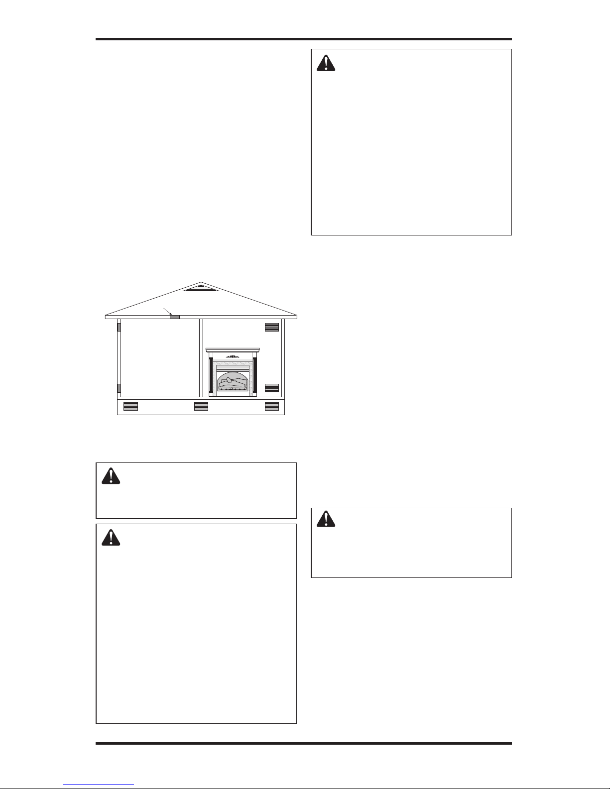
Figure 4 - Ventilation Air from Outdoors
Ventilation Air From Outdoors
Provide extra fresh air by using ventilation grills or
ducts. You must provide two permanent openings:
one within 12" of the ceiling and one within 12"
of the floor. Connect these items directly to the
outdoors or spaces open to the outdoors. These
spaces include attics and crawl spaces. Follow the
National Fuel Gas Code, ANSI Z223.1/NFPA 54,
Section 5.3, Air for Combustion and Ventilation for
required size of ventilation grills or ducts.
IMPORTANT: Do not provide openings for inlet
or outlet air into attic if attic has a thermostatcontrolled power vent. Heated air entering the attic
will activate the power vent.
INSTALLATION
WARNING: A qualified service person must install firebox.
Follow all local codes.
WARNING: Never install the
firebox
• in a bedroom or bathroom*
• in a recreational vehicle
• where curtains, furniture,
clothing or other flammable
objects are less than 42 inches
from the front, top or sides of
the firebox
• in high traffic areas
• in windy or drafty areas
* Unless the installed log set is
rated at 10,000 Btu/Hr or less.
Outlet
Air
Ve
ntilated
Attic
Outlet
A
ir
Inlet
Air
Inlet Air
Ve
ntilated
Crawl Space
To
Crawl
Space
To Attic
CAUTION: Log heaters installed in this firebox create warm
air currents. These currents move
heat to wall surfaces next to firebox. Installing firebox next to vinyl
or cloth wall coverings or operating firebox where impurities (such
as, but not limited to, tobacco
smoke, aromatic candles, cleaning fluids, oil or kerosene lamps,
etc.) in the air exist, may discolor
walls or cause odors.
IMPORTANT: Vent-free gas log heaters add moisture to the air. Although this is beneficial, installing
firebox in rooms without enough ventilation air may
cause mildew to form from too much moisture. See
Air for Combustion and Ventilation, page 7.
IMPORTANT: Make sure the firebox is level. If
firebox is not level, log set will not work properly.
Note: Your firebox is designed to be used in zero
clearance installations. Wall or framing material
can be placed against any exterior surface on the
rear, sides, top or bottom of your firebox, except
where standoff spacers are integrally attached. If
standoff spacers are attached to your firebox, these
spacers can be placed directly against wall or fram
ing materials. Use the dimensions shown for rough
opening to create the easiest installation.
Use dimensions shown for rough openings to
create the easiest installation (see Built-In Firebox
Installation, page 11).
INSTALLATION CLEARANCES
WARNING: Maintain the
minimum clearances. If you can,
provide greater clearances from
floor, ceiling and adjoining wall.
Carefully follow these instructions. This will
ensure safe installation.
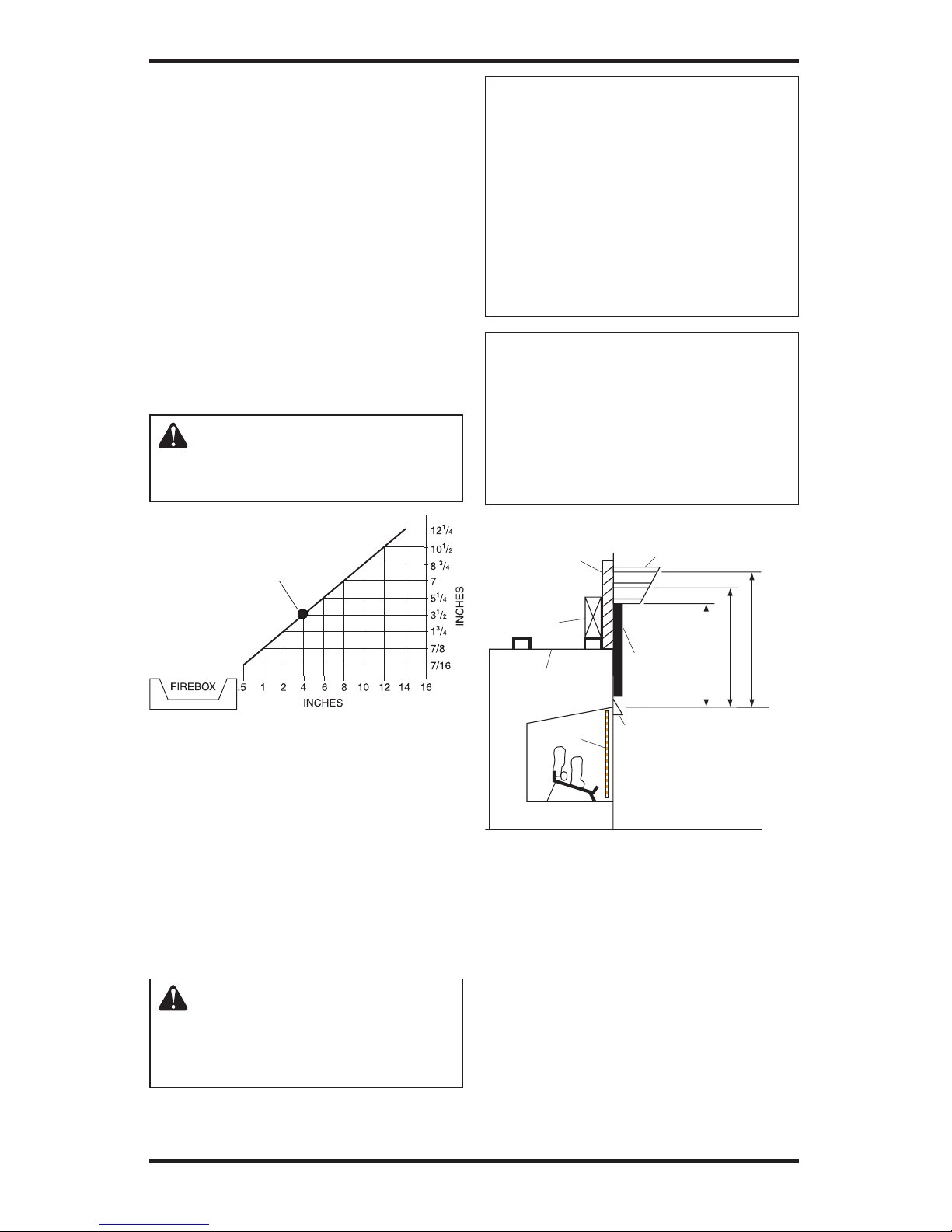
Minimum Wall and Ceiling Clearances (see
Figure 5, page 10)
A. Clearances from the side of the fireplace
cabinet to any combustible material and wall
should follow diagram in Figure 5, page 10.
Example: The face of a mantel, bookshelf,
etc. is made of combustible material and
protrudes 3 1/2" from the wall. This combustible material must be 4" from the side of the
fireplace cabinet (see Figure 5, page 10).
Page 10
www.desatech.com
115254-01A
10
B. Clearances from the top of the firebox opening to
the ceiling should not be less than 42 inches.
C. When the firebox is installed on carpeting or
other combustible material, other than wood
flooring, the firebox should be installed on a
metal or wood panel extending the full width
and depth of the enclosure.
D. Clearances from the bottom of firebox to the
floor is 0 inches.
These fireboxes can be installed as freestanding
units against a wall with the approved, optional
cabinet mantels (see
Accessories, page 35) or as a
built-in unit. The clearances are the same for either
installation method.
CAUTION: Do not install
the firebox directly on carpet
or vinyl.
INSTALLATION
Continued
Figure 5 - Minimum Clearance for
Combustible to Wall
*Minimum 16 inches from Side Wall
*
Mantel Clearances for Built-In Installation
If placing custom mantel above built-in firebox,
you must meet the minimum allowable clearance
between mantel shelf and top of firebox opening
shown in Figure 6. These are the minimum allow
able mantel clearances for a safe installation. Use
larger clearances wherever possible to minimize
the heating of objects and materials placed on
the mantel.
CAUTION: Do not allow
the vent-free gas log heater
to touch or extend beyond the
fireplace screen.
Example
NOTICE: Surface temperatures
of adjacent walls and mantels become hot during operation. Walls
and mantels above the firebox
may become hot to the touch.
If installed properly, these temperatures meet the requirement
of the national product standard.
Follow all minimum clearances
shown in this manual.
NOTICE: If your installation does
not meet the minimum clearances
shown, you must do one of the
following:
• raise the mantel to an acceptable height
• remove the mantel
BUILT-IN FIREBOX INSTALLATION
Built-in installation of this firebox involves installing firebox into a framed-in enclosure. This makes
the front of firebox flush with wall. Optional brass
trim accessories are available (see Accessories,
page 35). The brass trim will extend past sides of
firebox approximately 1/2 inch. This will cover
the rough edges of the wall opening. If installing
a mantel above the firebox, you must follow the
clearances shown in Figure 6. Follow these instructions to install the firebox in this manner.
Figure 6 - Minimum Mantel Clearances
for Built-In Installation
Supplied Firebox
Hood Must Be
Used at All Times
Wire-mesh
Screen
Firebox
Noncombustible
Material May
Project Off this
Surface above
the Firebox Hood
Mantel Shelf
Note: Any portion of the
mantel shelf must NOT
extend beyond this profile.
12"
16"
20"
1
1
/2
"
6
3
/4
"
12"
Note: All vertical
measurements are
from top of fireplace
hood opening to
bottom of mantel shelf.
These minimum
clearances replace any
other recommended
clearances supplied with
your ANSI Z21.11.2
approved gas logs.
Wa
ll board or facing
material (above
firebox) may be of
combustible material,
including decorative
mantel ornaments or
other similar projections off of the facing
material.
Framing
Material
Page 11
www.desatech.com
115254-01A 11
INSTALLATION
Continued
1. Frame in rough opening. The firebox framing should be constructed of 2 x 4 lumber or
heavier. Use dimensions in Table 1 and rough
opening layout in Figure 7a. Adjust framing so
that firebox flushes with finished wall surface. If
installing in a corner, use dimensions in Figures
7b, 7c and 7d for rough opening.
2. Install gas piping to firebox location (see
Connecting to Gas Supply, page 16.) IM
-
PORTANT:
If installing blower accessory
(circulating models with louvers only), see
Hard-Wiring Firebox,
page 15.
3. Carefully set firebox in front of rough open
-
ing with back of firebox inside wall opening.
IMPORTANT: If installing a perimeter trim kit,
see instructions included with trim accessory. You
must install shoulder screws from trim kit now.
4. Carefully insert firebox into rough opening.
5. Attach firebox to wall studs using nails or
wood screws through holes in nailing flange
(see Figure 8).
6. If using an optional perimeter trim kit, install
the trim after final finishing and/or painting
of wall. See instructions included with trim
accessory for attaching trim.
7. Install and properly test gas log heater. Follow
installation instructions included with the ventfree gas log heater that is being installed.
IMPORTANT:
When finishing your firebox, combustible materials such as wall board, gypsum board, sheet
rock, drywall, plywood, etc. may be butted up next to
the sides and top of the firebox. Combustible materials
should never overlap the firebox front facing.
WARNING: Do not allow any
combustible materials to overlap
the firebox front facing.
IMPORTANT: Noncombustible materials such as
brick, tile, etc. may overlap the front facing, but
should never cover any necessary openings like
louvered slots.
Front Width Depth
Model (Inside to Inside) Height (Min.)
32" 34 7/8" 36 3/4" 16 1/4"
36" 41
1
/2" 40 1/2" 20 3/4"
42" 48
5
/8" 44 1/2" 22 5/8"
Rough Opening Dimensions for
Built-in Installation
Table 1
Figure 7 - Rough Opening for Installing
in Wall
Depth
(Minimum)
Widt
h
(Inside to Inside)
Height
Figure 7a
37"
411/2"
5
2
11
/
32
"
74"
TOP
VIEW
FOR 36"
MODELS
Figure 7c
30"
347/8"
42
7
/
16
"
60"
TOP VIEW
FOR 32"
MODELS
43"
485/8"
6
0
13
/
1
6
"
86"
TOP
VIEW
FOR 42"
MODELS
Figure 7d
WARNING: Do not allow
noncombustible materials to
cover any necessary openings
like louvered slots.
WARNING: Use only noncombustible mortar or adhesives when overlapping the front
facing with noncombustible
facing material.
Figure 7b
Figure 8 - Attaching Firebox to Wall Studs
Nailing
Flanges
Nails or Wood
Screws
Page 12
www.desatech.com
115254-01A
12
INSTALLING FIREBOX USING
OPTIONAL ACCESSORY MANTELS
WARNING: A qualified service person must install firebox.
Follow all local codes.
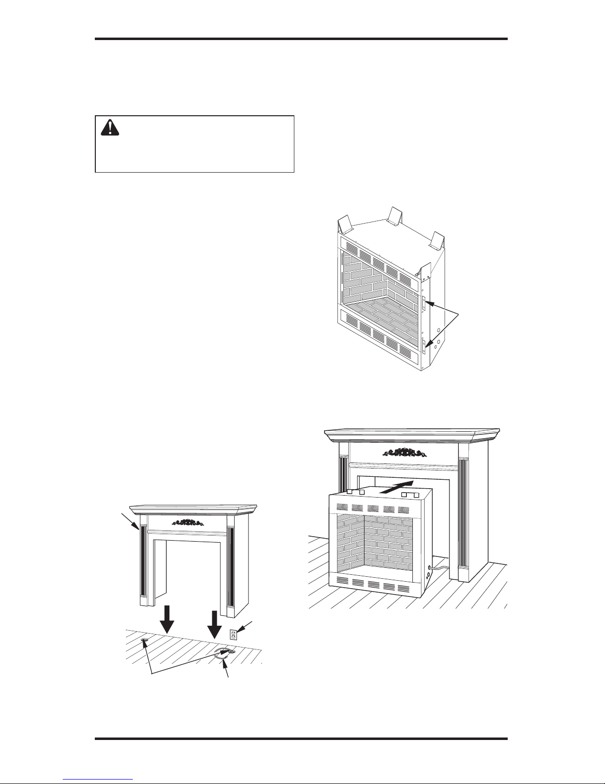
This firebox may be installed using a cabinet
mantel accessory against a wall in your home.
The firebox and cabinet mantel can be installed
directly on the floor. A trim kit is included with
the mantel accessories.
1. Assemble cabinet mantel accessory and the
trim kit. Assembly instructions are included
with each accessory.
2. If using an optional blower accessory (circulat
ing models only), install a properly grounded,
120 volt three-prong electrical outlet at firebox
location if an outlet is not there. If possible,
locate outlet so cabinet mantel will cover it
when installed (see Figure 9).
3. Install gas piping to firebox location. See
Connecting to Gas Supply, page 15. You may
have to cut an access hole in the floor or wall
to run gas line to firebox. Make sure to locate
access hole so cabinet mantel will cover it
when installed (see Figure 9).
4. Place cabinet mantel on floor in desired loca
-
tion. Make sure mantel is flush against wall.
5. Break off nailing flanges with hammer or pliers
(32" models only, see Figure 10).
INSTALLATION
Continued
6. Install the trim kit furnished with mantel. See instruction sheet included with the mantel now.
7. If installing an optional blower accessory (cir
culating models only), see Installing Optional
Blower Accessories, page 13.
8. Carefully insert firebox into cabinet mantel. Be
careful not to scratch firebox, cabinet mantel,
flooring, etc. when installing (see Figure 11).
9. Install and properly test gas log heater. Follow
installation instructions included with the ventfree gas log heater that is being installed.
Figure 9 - Installing Cabinet Mantel
Cabinet
Mantel
Gas Line Access Hole
(Either Side of Firebox)
Gas Piping
Electrical
Outlet
Figure 10 - Location of Nailing Flanges
(Two on Each Side), 32" Model Shown
(Model May Vary From Illustration)
Nailing
Flanges
Figure 11 - Inserting Firebox Into
Cabinet Mantel (Model May Vary From
Illustration)
Page 13
www.desatech.com
115254-01A 13
INSTALLATION
Continued
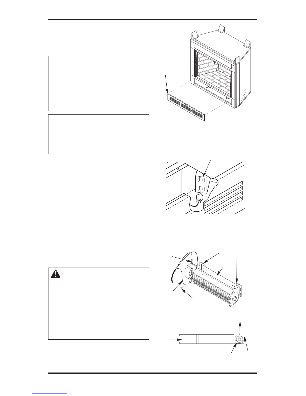
INSTALLING OPTIONAL BLOWER
ACCESSORIES
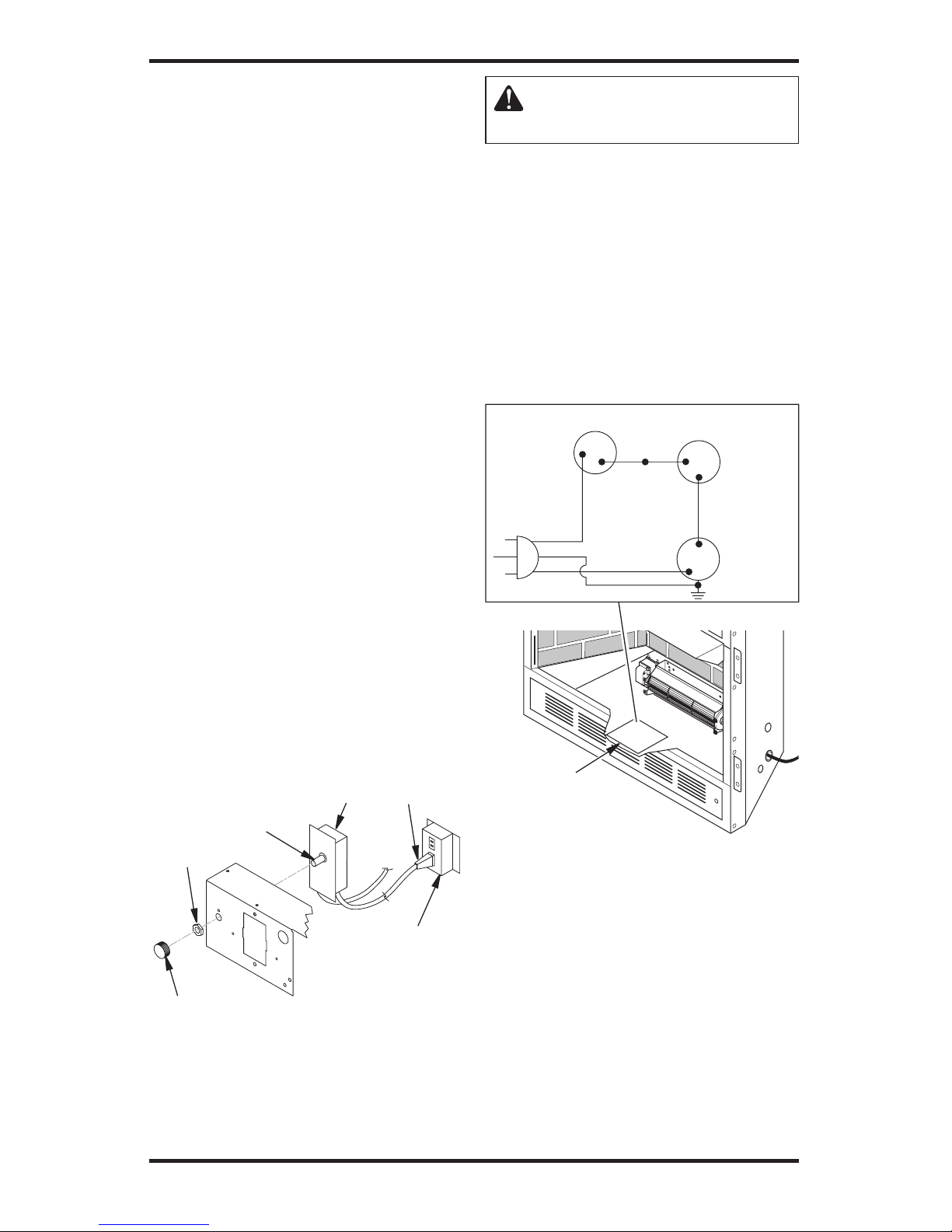
NOTICE: The firebox identification label (including model number, serial number, clearances,
etc.) is located in the right side
screen pocket area on the front
of the firebox. See Figure 25,
page 15.
NOTICE: If a log set is installed
in the firebox, disconnect log
set from gas supply and remove
from firebox. Contact a qualified
service person to do this.
Note: Appearance of firebox may vary depending
on model.
The blower accessory option for use in the ventfree fireboxes is model BK. Model BK is a rotary
squirrel cage type blower with magnetic attach
-
ment and variable speed control.
The blower is installed by removing the lower face
panel. To remove the lower face panel, pull the left
and right latches toward the center of the appliance
until they are disengaged from their locator holes
(see Figure 12).
Models with louvered front panels can also be
removed by inserting fingertips between slots
and gently pulling out. DO NOT FORCE. The
panels are actually held in place by means of a
retention dimple embossed on the edge of remov
-
able panels.
WARNING: If there is a duplex
electrical outlet installed in the
right side of the bottom of the
fireplace base area (see Figure
13), be sure that the electrical
power to the outlet is turned off
before proceeding with blower
installation. Failure to do this
may result in serious injury.
1. Attach the power cord to the blower motor by
firmly pushing the two female terminals at the
end of the power cord onto the two spade terminals on the blower motor (see Figure 14).
Figure 12 - Accessing Blower
Compartment (Controls Not Shown
for Clarity)
Lower
Louver
Panel
Duplex Electrical Outlet
Figure 13 - Accessing Duplex Electrical
Outlet Installed in Bottom Right Side of
Firebox
Figure 14 - Blower Model BK
Magnetic Strips
Exhaust
Port
Screw
Green
Ground
Wire
Spade
Terminals
Side View
Firebox Bottom
Air Flow
Direction
Blower
Installed
After
Lower
Panel
Removed
Blower
Location
Magnets
Page 14
www.desatech.com
115254-01A
14
2. Attach green ground wire from power cord
to blower housing using screw provided (see
Figure 14, page 13). Tighten screws securely
with a phillips screwdriver.
3. Place the blower against the lower rear wall of
the firebox outer wrapper with the exhaust port
directed upward. Depending on your model,
you may have to carefully route the blower
assembly past the controls and brackets and
position the blower inside the back opening.
The blower will be held in position against the
back wall by the magnets incorporated onto
the blower housing (see Figure 14, page 13).
4. Be certain that all wire terminals are securely at
tached to terminals on blower motor and that the
screw retaining the green ground wire is tight.
5. Mount speed control box by placing plastic con
trol shaft through bottom hole on speed control
bracket. Top screw head on control box will fit
inside top hole on bracket (see Figure 15). Secure
speed control to bracket with lock nut by pushing
and turning lock nut with pliers clockwise until
it is tight against bracket.
6. Place control knob, provided, onto control
shaft (see Figure 15).
7. Check to make sure power cord is completely
clear of blower wheel and there are no foreign
objects in blower wheel. Also, double check
all wire leads and make sure wire routing is
not pinched or in a precarious position. Cor
-
rect accordingly.
INSTALLATION
Continued
CAUTION: Never touch the
blower wheel while in operation.
8. Turn on power to duplex outlet if previously
turned off per warning on page 13.
9. Plug in blower power cord to duplex outlet
(see Figure 15, page 13).
10. Turn blower on and check for operation. Turn
blower off by turning knob fully counterclock
-
wise before continuing.
11. Peel off backing paper and stick supplied wiring
diagram decal on firebox bottom approximately
12" in from of blower (see Figure 16).
12. Replace all panels and/or brick bottom panel
if previously removed.
Figure 15 - Attaching Speed Control to
Firebox with Panel Louvers
Figure 16 - Location of Wiring Diagram
Decal (Model May Vary From Illustration)
Wiring Diagram
Decal 12" in
Front of Blower
Red
Va
riable
Fan Switch
Fan Switch
(N.O.)
Green
White
On
11
0/115
V.
A.C.
Blower
Motor
Black
Off
1
2
Black
Blue
(BKT Model
Only)
Control
Shaft
Locknut
Control Knob
Speed
Control
Blower
Plug-In
Duplex Outlet
(Located under
firebox floor
against lower
right outside wall)
Page 15
www.desatech.com
115254-01A 15
INSTALLATION
Continued
HARD-WIRING FIREBOX
NOTICE: A qualified electrician
must connect electrical wiring to
duplex outlet for built-in instal
lation. Follow all local codes.
In absence of local codes fol
low The National Electric Code
ANSI/NFPA 70.
The “Handy Box” with duplex outlet is provided in
the firebox located in the lower right base area.
1. Remove screw holding duplex outlet cover to
handy box. Remove duplex outlet.
2. Route electrical cable through strain relief and
handy box (see Figure 17).
3. Connect electrical cable to duplex outlet.
Match wire colors to those on duplex outlet.
Be sure to connect the ground wire.
4. Place duplex outlet back into handy box and
secure with screws. Replace outlet cover.
Strain Relief
Duplex Box/
Handy Box
Figure 17 - Hard-Wiring Firebox
INSTALLING FIREPLACE HOOD
AND SCREEN
1. Attach hood to firebox using screws provided
(see Figure 18).
2. Insert each rod through all rings located at top
of screen.
3. Insert first rod into rear hole in left side of
firebox. Fasten rod to rear hole near center
of firebox using #10 x 3/8" Phillips screw
provided (see Figure 19).
4. Insert other rod into front hole on right side
of firebox and fasten using remaining Phillips
screw.
Figure 18 - Screw and Hood Placement
(Model May Vary From Illustration)
Figure 19 - Installing Fireplace Screen
(Model May Vary From Illustration)
Screw
Rear Hole
Top View of Rod Layout
Rod
Front
Hole
Ring
Screen
Identification
Label Location
Page 16
www.desatech.com
115254-01A
16
INSTALLATION
Continued
CONNECTING TO GAS SUPPLY
WARNING: This appliance
requires a 1/2" NPT (National
Pipe Thread) inlet connection to
the pressure regulator.
WARNING: A qualified service person must connect heater
to gas supply. Follow all local
codes.
CAUTION: Never connect
propane/LP fireplace directly
to the propane/LP supply. This
heater requires an external regu
lator (not supplied). Install the
external regulator between the
heater and propane/LP supply.
WARNING: Never connect
natural gas fireplace to private
(non-utility) gas wells. This
gas is commonly known as
wellhead gas.
Installation Items Needed
Before installing heater, make sure you have the
items listed below.
• external regulator (supplied by installer)
• piping (check local codes)
• sealant (resistant to propane/LP gas)
• equipment shutoff valve *
• test gauge connection *
• sediment trap
• tee joint
• pipe wrench
• approved flexible gas line with gas connector
(if allowed by local codes) (not provided)
* A CSA design-certified equipment shutoff valve
with 1/8" NPT tap is an acceptable alternative to
test gauge connection. Purchase the optional CSA
design-certified equipment shutoff valve from your
dealer. See
Accessories, page 35.
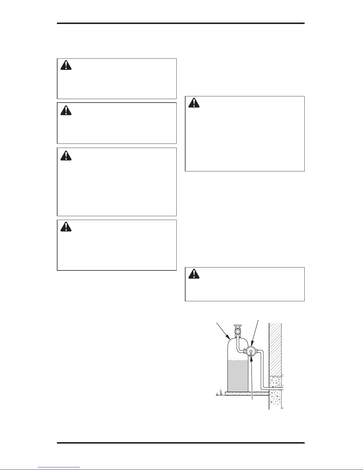
For propane/LP units, the installer must supply
an external regulator. The external regulator will
reduce incoming gas pressure. You must reduce
incoming gas pressure to between 11 and 14 inches
of water. If you do not reduce incoming gas pres
sure, heater regulator damage could occur. Install
external regulator with the vent pointing down
as shown in Figure 20. Pointing the vent down
protects it from freezing rain or sleet.
CAUTION: Use only new, black
iron or steel pipe. Internally-tinned
copper tubing may be used in
certain areas. Check your local
codes. Use pipe of 1/2" diameter
or greater to allow proper gas volume to heater. If pipe is too small,
undue loss of volume will occur.
Installation must include an equipment shutoff
valve, union and plugged 1/8" NPT tap. Locate
NPT tap within reach for test gauge hook up. NPT
tap must be upstream from heater (see Figure 21
or 22, page 17, depending on your model).
IMPORTANT: Install equipment shutoff valve in an
accessible location. The equipment shutoff valve is for
turning on or shutting off the gas to the appliance.
Apply pipe joint sealant lightly to male NPT
threads. This will prevent excess sealant from
going into pipe. Excess sealant in pipe could result
in clogged heater valves.
WARNING: Use pipe joint
sealant that is resistant to liquid
petroleum (LP) gas.
External Regulator
Propane/LP
Supply Tank
Vent Pointing Down
Figure 20 - External Regulator with Vent
Pointing Down
Page 17

www.desatech.com
115254-01A 17
Tee Cap Pipe
Joint Nipple
We recommend that you install a sediment trap in
supply line as shown in Figures 21 and 22, depend
ing on your model. Locate sediment trap where it is
within reach for cleaning. Install in piping system
between fuel supply and heater. Locate sediment
trap where trapped matter is not likely to freeze.
A sediment trap traps moisture and contaminants.
This keeps them from going into heater controls. If
sediment trap is not installed or is installed wrong,
heater may not run properly.
CAUTION: Avoid damage to
regulator. Hold gas regulator
with wrench when connecting
it to gas piping and/or fittings
(Variable Manually-Controlled
Models Only).
CAUTION: Avoid damage to
gas control. Hold gas control
with wrench when connecting
it to gas piping and/or fittings
(Remote-Ready Models Only).
Figure 22 - Attaching Flexible Gas Line
to Control Valve (Remote-Ready Models)
* Purchase the optional CSA design-certified
equipment shutoff valve from your dealer. See
Accessories, page 35.
**Minimum inlet pressure for purpose of input
adjustment
Approved
Flexible
Gas Hose (if
allowed by
local codes)
Pipe Cap Tee
Nipple Joint
3" Minimum
Sediment Trap
Propane/LP
- From External
Regulator
(11" W.C.** to 14"
W.C. Pressure)
Natural - From
Gas Meter (5"
W.C.** to 10.5"
W.C. Pressure)
Gas
Control
CSA Design-Certified
Equipment Shutoff Valve
with 1/8" NPT Tap*
CHECKING GAS CONNECTIONS
WARNING: Test all gas piping
and connections, internal and
external to unit, for leaks after
installing or servicing. Correct
all leaks at once.
WARNING: Never use an
open flame to check for a leak.
Apply a noncorrosive leak detection fluid to all joints. Bubbles
forming show a leak. Correct all
leaks at once.
CAUTION: Make sure external regulator has been installed
between propane/LP supply and
heater. See guidelines under Con-
necting to Gas Supply, page 16.
INSTALLATION
Continued
Figure 21 - Attaching Flexible Gas Line to
Control Valve (Manually-Controlled Models)
Propane/LP
From External
Regulator
(11" W.C.**
to 14" W.C.
Pressure)
Natural
From Gas
Meter (5"
W.C.** to
10.5" W.C.
Pressure)
CSA DesignCertified Equipment
Shutoff Valve with
1/8" NPT Tap*
Approved
Flexible
Gas Hose (if
allowed by
local codes)
3" Minimum
Sediment Trap
Gas
Regulator
Page 18

www.desatech.com
115254-01A
18
Propane/LP
Supply Tank
PRESSURE TESTING GAS SUPPLY
PIPING SYSTEM
Test Pressures In Excess Of 1/2 PSIG
(3.5 kPa)
1. Disconnect appliance with its appliance main
gas valve (control valve) and equipment
shutoff valve from gas supply piping system.
Pressures in excess of 1/2 psig will damage
heater regulator.
2. Cap off open end of gas pipe where equipment
shutoff valve was connected.
3. Pressurize supply piping system by either
opening propane/LP supply tank valve for
propane/LP gas or opening main gas valve
located on or near gas meter for natural gas
or using compressed air.
4. Check all joints of gas supply piping system.
Apply noncorrosive leak detection fluid to all
joints. Bubbles forming show a leak.
5. Correct all leaks at once.
6. Reconnect heater and equipment shutoff
valve to gas supply. Check reconnected fit
-
tings for leaks.
Test Pressures Equal To or Less Than
1/2 PSIG (3.5 kPa)
1. Close equipment shutoff valve (see Figure 23).
2. Pressurize supply piping system by either
opening propane/LP supply tank valve for
propane/LP gas or opening main gas valve
located on or near gas meter for natural gas
or using compressed air.
3. Check all joints from gas meter to equipment
shutoff valve for natural gas or propane/LP
supply to equipment shutoff valve for propane/
LP (see Figure 24 and 25). Apply noncorrosive
leak detection fluid to all joints. Bubbles form
-
ing show a leak.
4. Correct all leaks at once.
Open
Closed
Equipment
Shutoff Valve
Figure 23 - Equipment Shutoff Valve
INSTALLATION
Continued
Equipment
Shutoff Valve
Figure 25 - Checking Gas Joints
(Natural Gas Only)
Figure 24 - Checking Gas Joints
(Propane/LP Gas Only)
Equipment Shutoff Valve
Gas
Meter
Control Valve Location
Control Valve Location
PRESSURE TESTING HEATER GAS
CONNECTIONS
1. Open equipment shutoff valve (see Figure 23).
2. Open main gas valve located on or near gas
meter for natural gas or open propane/LP
supply tank valve.
3. Make sure control knob of heater is in the OFF
position.
4. Check all joints from equipment shutoff valve
to control valve (Manually-Controlled Mod
els) or to gas control (Remote-Ready Models)
(see Figures 24 and 25). Apply noncorrosive
leak detection fluid to all joints. Bubbles form
ing show a leak.
5. Correct all leaks at once.
6. Light heater (see Operating Fireplace, page 21).
Check all other internal joints for leaks.
7. Turn off heater (see To Turn Off Gas to Appli
-
ance, page 23 for Manually-Controlled Mod-
els or page 25 for Remote-Ready Models).
Page 19
www.desatech.com
115254-01A 19
INSTALLING LOGS
(Models (V)L32HN, (V)L32LHN.
(V)L32HP
and (V)L32LHP
WARNING: Failure to position the parts in accordance
with these diagrams or failure
to use only parts specifically
approved with this heater may
result in property damage or
personal injury.
CAUTION: After installation and periodically thereafter,
check to ensure that no flame
comes in contact with any log.
With the heater set to HI, check
to see if flames contact any log. If
so, reposition logs according to
the log installation instructions
in this manual. Flames contacting logs will create soot.
Vintage Oak Two-Piece Log Set
It is very important to install these logs exactly
as instructed. Do not modify logs. Only use logs
supplied with heater.
1. Place front log on top of the grate and over front
posts on chassis (see Figure 26).
Front Post
Figure 26 - Installing Vintage Oak Two-
Piece Log Set
Figure 27 - Installing Vintage Oak Two-
Piece Log Set (Top View)
Two Piece Log Set
Burner Ports
Log #2
Chassis
Rear
Post
Log #1
INSTALLING LOGS
Models L36(EN, LEN, EP, LEP) and
VL36(EN, LEN, EP, LEP)
WARNING: Failure to position the parts in accordance
with these diagrams or failure
to use only parts specifically
approved with this heater may
result in property damage or
personal injury.
It is very important to install these logs exactly
as instructed. Do not modify logs. Only use logs
supplied with heater.
Note: Your appliance may vary from model shown
but log placement will be the same.
1. Place front logs (1L and 1R) on top of grate.
Make sure notches in bottom of logs fit over
grate prongs (see Figure 28).
2. Rest bottom of center log (#2) behind metal
posts on front burner (see Figure 29, page 20).
Make sure grooves in bottom of log fit over
grate. Bring log forward against metal posts.
INSTALLATION
Continued
Figure 28 - Installing Front Logs
Front Logs
Notch
Grate
Prong
2. Place rear log on rear of chassis (see Figure 26).
Slide log forward so that it sits against rear posts
on chassis. IMPORTANT: Make sure logs do
not cover any burner ports (see Figure 27).
3. Place lava rock around base of heater if desired.
Page 20

www.desatech.com
115254-01A
20
Figure 30 - Installing Rear Log (#3)
Figure 31 - Installing Crossover Log (#4)
INSTALLING LOGS
Models (V)L36(ZNR, LZNR, ZPR, LZPR)
and (V)L42(ZNR, LZNR, ZPR, LZPR)
WARNING: Failure to position the parts in accordance
with these diagrams or failure
to use only parts specifically
approved with this heater may
result in property damage or
personal injury.
Each log is marked with a number. These numbers
will help you identify the log when installing. It
is very important to install these logs exactly as
instructed. Do not modify logs. Only use logs
supplied with heater.
Note:
Your appliance may vary from model shown
but log placement will be the same.
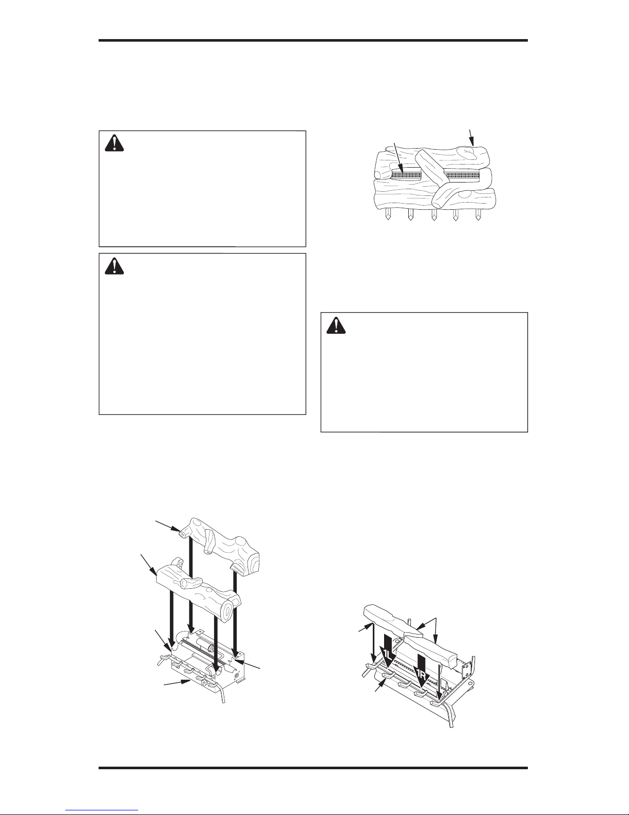
1. Place ember bed in center of the base assembly
as shown in Figure 32.
2. Rest rear log in back corner sections of base as
sembly as shown in Figure 32. Make sure log is
completely vertical and not leaning in toward
burner where the flame will touch the log.
3. Position middle log as shown in Figure 32
making sure the grooves in the bottom of the
log fit over the grate prongs. This log will rest
on top of the bottom log.
Base
Assembly
Figure 32- Installing Ember Bed, Rear
and Middle Logs
Ember
Bed
Rear Log
Middle Log
3. Slide groove on back of rear log against the rear
grate prongs. Make sure the peg on the log is
on top (see Figure 30).
4. Place the crossover log on the rear and middle
logs. Make sure peg on rear log is in the hole in
bottom of crossover log. The crossover log should
fit in cutout of middle log (see Figure 31).
INSTALLATION
Continued
Rear Log
(#3)
Rear
Grate
Prong
Crossover
Log (#4)
Peg
Figure 29 - Installing Center Log
Center Log (#2)
Grate
Metal Post
Metal
Post
Page 21

www.desatech.com
115254-01A 21
Figure 33 - Installing Top Logs
Figure 34 - Installing Front Logs
Middle
Log
Top Left Log
Top Right Log
Left Front
Log
Right Front Log
4.
Place top right log onto pins of middle log
(see Figure 32, page 20). The bottom of the
top log will rest on the middle log as shown
in Figures 33 and 34.
5. Place top left log on middle log as shown in
Figure 33.
6. Place right and left front logs against grate as
shown in Figure 34 to hide the controls.
INSTALLATION
Continued
OPERATING FIREPLACE
MANUALLY-CONTROLLED
MODELS
FOR YOUR SAFETY
READ BEFORE LIGHTING
WARNING: If you do not follow these instructions exactly,
a fire or explosion may result
causing property damage, personal injury or loss of life.
A. This appliance has a pilot which must be
lighted by hand. When lighting the pilot,
follow these instructions exactly.
B. BEFORE LIGHTING smell all around the
appliance area for gas. Be sure to smell next
to the floor because some gas is heavier than
air and will settle on the floor.
WHAT TO DO IF YOU SMELL GAS
• Do not try to light any appliance.
• Do not touch any electric switch; do not
use any phone in your building.
• Immediately call your gas supplier from
a neighbor ʼs phone. Follow the gas
supplierʼs instructions.
• If you cannot reach your gas supplier, call
the fire department.
C. Use only your hand to push in or turn the
gas control knob. Never use tools. If the
knob will not push in or turn by hand, donʼt
try to repair it, call a qualified service tech
nician or gas supplier. Force or attempted
repair may result in a fire or explosion.
D. Do not use this appliance if any part has
been under water. Immediately call a
qualified service technician to inspect the
appliance and to replace any part of the
control system and any gas control which
has been under water.
Page 22

www.desatech.com
115254-01A
22
LIGHTING
INSTRUCTIONS
WARNING:
• If fireplace has glass doors,
never operate this heater with
glass doors closed. If you op
erate heater with doors closed,
heat buildup inside fireplace
will cause glass to burst. Make
sure there are no obstructions
across openings of fireplace.
• You must operate this heater
with a fireplace screen in
place. Make sure fireplace
screen is closed before running heater.
NOTICE: During initial operation
of new heater, burning logs will
give off a paper-burning smell.
Orange flame will also be pres
ent. Open damper or window to
vent smell. This will only last a
few hours.
Note: Home owners generally prefer to operate their heater with the chimney damper
closed. This will put all the heat into the room.
However, there may be times you will desire
the full flames of the High heat setting but will
find the heat output excessive. You can open
the chimney damper (if you have one) fully or
partially to release some of the heat.
WARNING: Damper handle
will be hot if heater has been
running.
1. STOP! Read the safety information in
column 2, page 21.
2. Make sure equipment shutoff valve is fully
open.
3. Press in and turn control knob clockwise
to the OFF position.
LO
HI
OFF
PILOT
Thermocouple
Ignitor Electrode
Pilot Burner
4. Wait five (5) minutes to clear out any gas.
Then smell for gas, including near the floor.
If you smell gas, STOP! Follow “B” in the
safety information in column 1. If you donʼt
smell gas, go to the next step.
5. Press in control knob and turn counter
clockwise to the PILOT position.
Keep control knob pressed in for five (5)
seconds (see Figure 35).
Note: You may be running this heater for
the first time after hooking up to gas sup
ply. If so, the control knob may need to be
pressed in for 30 seconds or more. This will
allow air to bleed from the gas system.
6. With control knob pressed in, press and release
ignitor button. This will light pilot. The pilot is
attached to the front burner. If needed, keep
pressing ignitor button until pilot lights.
Note: If pilot does not light, contact a
qualified service person or gas supplier for
repairs. Until repairs are made, light pilot
with match. To light pilot with match, see
Manual Lighting Procedure, page 23.
7. Keep control knob pressed in for 30 seconds
after lighting pilot. After 30 seconds, release
control knob.
• If control knob does not pop out when
released, contact a qualified service person
or gas supplier for repairs.
Note: If pilot goes out, repeat steps 3
through 7.
8. Push in and turn control knob counter
clockwise to the HI position. Both
burners should light. Set control knob to
desired setting.
Figure 35 - Control Knob and Ignitor
Button Location
Figure 36- Pilots
OPERATING FIREPLACE
Continued
Ignitor
Button
Control Knob
Thermocouple
Ignitor
Electrode
Pilot Burner
Page 23

www.desatech.com
115254-01A 23
OPERATING FIREPLACE
Continued
VARIABLE CONTROL
OPERATION
The variable control valve can be set to any
heat setting and flame height desired, by sim
ply turning the control knob until that setting
is attained. Even the lowest setting provides
realistic flames and glowing embers from two
burners. Selecting higher settings produces
greater heat output. This results in increased
heating comfort.
WARNING: Do not operate
heater between locked positions.
CAUTION: Do not try to adjust heating levels by using the
equipment shutoff valve.
TO TURN OFF GAS
TO APPLIANCE
Shutting Off Heater
1. Press in and turn control knob clockwise
to the HI position.
2. Turn the control knob clockwise
to
the PILOT position.
3. Press in control knob and turn clockwise
to the OFF position.
Shutting Off Burners Only (pilot stays lit)
1. Turn the control knob clockwise
to
the HI position.
2. Press in and turn control knob clockwise
to the PILOT position.
MANUAL LIGHTING
PROCEDURE
1. Follow steps 1 through 5 under Lighting
Instructions, page 22.
2. Depress control knob and light pilot with
match.
3. Keep control knob pressed in for 30 seconds
after lighting pilot. After 30 seconds, release
control knob. Now follow step 8, column 2,
page 22.
REMOTE-READY MODELS
FOR YOUR SAFETY READ
BEFORE LIGHTING
WARNING: If you do not follow these instructions exactly,
a fire or explosion may result
causing property damage, personal injury or loss of life.
A. This appliance has a pilot which must be
lighted by hand. When lighting the pilot,
follow these instructions exactly.
B. BEFORE LIGHTING smell all around the
appliance area for gas. Be sure to smell next
to the floor because some gas is heavier than
air and will settle on the floor.
WHAT TO DO IF YOU SMELL GAS
• Do not try to light any appliance.
• Do not touch any electric switch; do not
use any phone in your building.
• Immediately call your gas supplier from
a neighbor ʼs phone. Follow the gas
supplierʼs instructions.
• If you cannot reach your gas supplier, call
the fire department.
C. Use only your hand to push in or turn the
gas control knob. Never use tools. If the
knob will not push in or turn by hand, donʼt
try to repair it, call a qualified service tech
nician or gas supplier. Force or attempted
repair may result in a fire or explosion.
D. Do not use this appliance if any part has
been under water. Immediately call a
qualified service technician to inspect the
appliance and to replace any part of the
control system and any gas control which
has been under water.
Page 24

www.desatech.com
115254-01A
24
LIGHTING
INSTRUCTIONS
WARNING
• If fireplace has glass doors,
never operate this heater with
glass doors closed. If you op
erate heater with doors closed,
heat buildup inside fireplace
will cause glass to burst. Make
sure there are no obstructions
across openings of fireplace.
• You must operate this heater
with a fireplace screen in place.
Make sure fireplace screen is
closed before running heater.
NOTICE: During initial operation of
new heater, burning logs will give
off a paper-burning smell. Orange
flame will also be present. Open
damper or window to vent smell.
This will only last a few hours.
Note: Home owners generally prefer to operate their heater with the chimney damper
closed. This will put all the heat into the room.
However, there may be times you will desire
the full flames of the HI heat setting but will
find the heat output excessive. You can open
the chimney damper (if you have one) fully or
partially to release some of the heat.
WARNING: Damper handle will
be hot if heater has been running.
1. STOP! Read the safety information, starting in column 2.
2. Make sure equipment shutoff valve is
fully open.
3. Set selector switch in the OFF position.
4. Press in and turn control knob clockwise
to the OFF position (see Figure 37).
WARNING: Burners will
come on automatically within
one minute when the selector
switch is in the ON position after
the pilot is lit.
5. Wait five (5) minutes to clear out any gas.
Then smell for gas, including near the floor.
If you smell gas, STOP! Follow “B” in the
safety information, starting in column 2,
page 23. If you donʼt smell gas, go to the
next step.
6. Press in and turn control knob counter
-
clockwise
to the PILOT position.
Press in control knob for five (5) seconds
(see Figure 37).
Note: You may be running this heater for
the first time after hooking up to gas sup
ply. If so, the control knob may need to be
pressed in for 30 seconds or less. This will
allow air to bleed from the gas system.
7. With control knob pressed in, press and
release ignitor button. This will light pilot.
The pilot is attached to the front burner. If
needed, keep pressing ignitor button until
pilot lights.
Note: If pilot does not stay lit, contact a
qualified service person or gas supplier for
repairs. Until repairs are made, light pilot
with match. To light pilot with match, see
Manual Lighting Procedure, page 25.
8. Keep control knob pressed in for 30 seconds
after lighting pilot. After 30 seconds, release
control knob.
• If control knob does not pop out when
released, contact a qualified service person
or gas supplier for repairs.
Note: If pilot goes out, repeat steps 4
through 8.
O
F
F
P
I
L
O
T
L
O
I
H
ON
OFF
REMOTE
O
N
Figure 37 - Control Knob and Ignitor
Button Location
Control Knob
Ignitor Button
Selector
Switch in
OFF Position
Flame
Adjustment
Knob
OPERATING FIREPLACE
Continued
Page 25

www.desatech.com
115254-01A 25
OPERATING FIREPLACE
Continued
9. Slightly push in and turn control knob counterclockwise
to the ON position.
10. Wait one minute and switch selector switch
to the ON position to light burners. Note:
AUTO is only functional when using
GWMT1 or GWMS2 optional accessories.
CAUTION: Do not try to adjust heating levels by using the
equipment shutoff valve.
WARNING: Make sure the
selector switch is in the OFF
position when you are away from
home for long periods of time.
Heater will come on automati
cally with selector switch in the
ON position.
Figure 38 - Propane/LP Pilot (Pilots may
vary by model)
Ignitor
Electrode
Pilot Burner
Figure 39 - Natural Pilot (Pilots may vary
by model)
Ignitor
Electrode
Pilot Burner
TO TURN OFF GAS
TO APPLIANCE
Shutting Off Heater
1. Turn control knob clockwise
to the
OFF position.
2a. Set selector switch in the OFF position.
2b. If Using Optional Hand-Held Remote:
Set selector switch in the OFF position to
prevent draining battery.
Shutting Off Burners Only (pilot stays lit)
You may shut off the burners and keep the pilot
lit by doing one of the following:
1. Turn control knob clockwise
to the
PILOT position.
2. Use remote control manual OFF button.
3. Set selector switch in the OFF position.
MANUAL LIGHTING
PROCEDURE
1. Follow steps 1 through 6 under Lighting
Instructions, page 24.
2. Depress control knob and light pilot with
match.
3. Keep control knob pressed in for 30 seconds
after lighting pilot. After 30 seconds, release
control knob. Now follow steps 9 and 10
under
Lighting Instructions, column 1.
OPTIONAL HAND-HELD
REMOTE OPERATION
Note: All remote control accessories must be
purchased separately (see Accessories, page
35). Follow instructions included with the
remote control.
NOTICE: You must light the pilot
before using the hand-held remote control unit. See Lighting
Instructions on page 24.
After lighting, let pilot flame burn for about
one minute. Turn control knob to ON posi
tion. Adjust flame adjustment knob anywhere
between HI and LO. Slide the selector switch
to the REMOTE position (see Figure 40).
Note: The burner may light if hand-held
remote was on when selector switch was last
turned off. You can now turn the burner on and
off with the hand-held remote control unit.
IMPORTANT: Do not leave the selector switch
in the REMOTE or ON position when the pilot
is not lit. This will drain the battery.
Figure 40 - Setting the Selector switch,
Control Knob and Flame Adjustment
Knob for Remote Operation
O
F
F
P
I
L
O
T
L
O
I
H
ON
OFF
REMOTE
O
N
Selector Toggle Switch
(Optional Remote Control)
Control Knob in
On Position
Flame Adjustment
Knob
Page 26
www.desatech.com
115254-01A
26
OPERATING FIREPLACE
Continued
Figure 41 - On/Off Hand-Held Remote
Control Unit (GHRCB)
Control Button
Turns Burners On
and Off
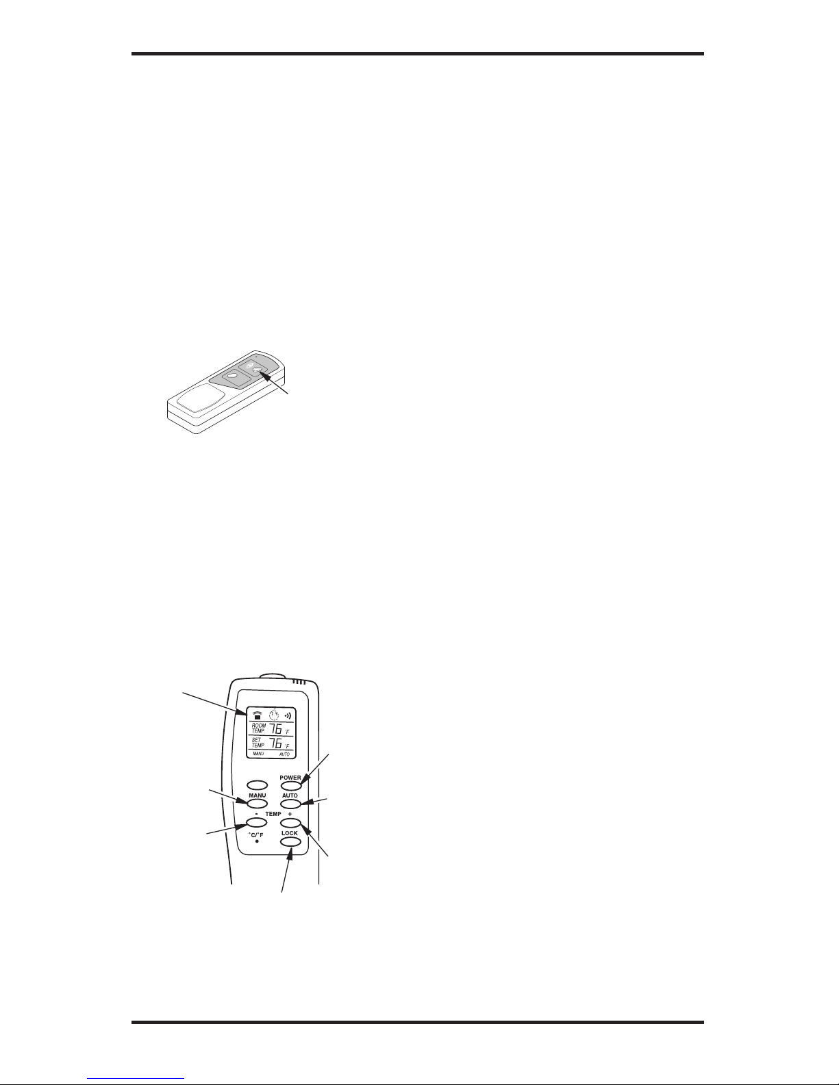
THERMOSTAT SERIES (MODEL
GHRCTB)
The hand-held remote can be operated using
either the manual mode (MANU) or thermostatic mode (AUTO) (see Figure 42). To select
Fahrenheit/Centigrade mode display, carefully
press the ˚C/˚F mode button with the end of a
paper clip or similar blunt object.
ON/OFF SERIES (MODEL GHRCB)
Hold the control button on the hand-held remote
until burner turns on. Hold the control button
again until burner turns off (see Figure 41).
To Lock press both buttons on hand-held
remote control until light stops flashing. Handheld remote control is now locked. If the fire is
on it will be turned off automatically. In the
locked state, the light will not light up when
any button is pressed.
To Unlock press both buttons together on handheld remote control until the light stops flashing.
The hand-held remote is now unlocked.
Figure 42 - Thermostat Hand-Held
Remote Control Unit (GHRCTB)
Turns
Hand-Held
Remote On
or Off and
Allows You
to Choose
the Manual
Setting
Selects
Auto Setting
Increases
Room
Temperature
in AUTO
Mode
Digital
Display
Shows
Temperature
and Settings
Turns
Burners On
or Off
Decreases
Room
Temperature
in AUTO
Mode
Manual Mode
1. Press the POWER and LOCK buttons togeth-
er to turn on the hand-held remote control.
2. Press the MANU button to turn on the
fireplace.
3. Press the POWER and LOCK buttons
together to turn off the fireplace.
Auto (Thermostatic) Mode
1. Press the POWER and LOCK buttons togeth-
er to turn on the hand-held remote control.
2. Press AUTO button to select this mode.
3. Set the desired room temperature by press
-
ing the TEMP + or - buttons.
4. Press the POWER and LOCK buttons
together to turn off the fireplace
Note: Do not leave the hand-held remote in the
AUTO mode close to the fireplace. The radiant
heat from the fireplace will turn off the fireplace.
Ideally, place the hand-held remote in the center
of the room facing towards the fireplace.
Note: Do not hold the hand-held remote for
a long time. Body temperature will affect its
operation in the AUTO mode.
Safety Features
When away from home for an extended period
of time or as a child safety feature to prevent
accidental ignition of the fireplace, the receiver
ON/OFF/REMOTE switch should be in the
OFF position.
Auto Shutoff Feature
1. If the average room temperature exceeds
82 degrees Fahrenheit (28 degrees Centigrade), the hand-held remote control will
perform a safety override and shut the
fireplace off. This feature is not available
in the MANU mode.
2. The receiver continuously receives signals
from the hand-held remote to control the
room temperature. If the hand-held remote
is misplaced, obstructed or for any reason
cannot transmit to the receiver, the receiver
will shut off the fireplace after 8 minutes.
Key Pad Lock Feature
This feature allows the user to lock/unlock
the keypad on the hand-held remote in the
MANU or AUTO mode to prevent inadvertent
operation (i.e. children operating the hand-held
remote control, etc.). The keypad is locked in
either on or off. Press the POWER and LOCK
buttons together to turn the unit on or off.
Locks System to
Prevent Accidental
Ignition
Page 27
www.desatech.com
115254-01A 27
INSPECTING BURNERS
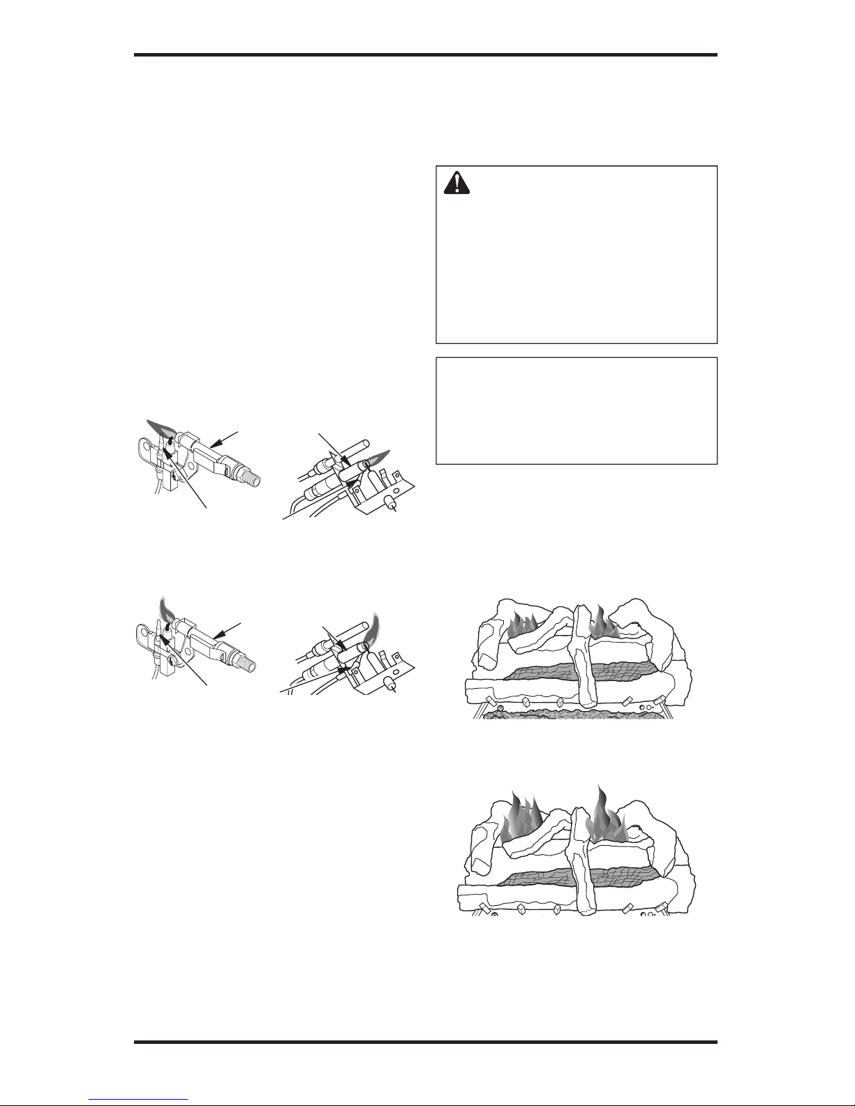
Check pilot flame pattern and burner flame patterns often.
PILOT FLAME PATTERN
Figure 43 shows a correct pilot flame pattern. Figure
44 shows an incorrect pilot flame pattern. The incor
rect pilot flame is not touching the thermocouple.
This will cause the thermocouple to cool. When the
thermocouple cools, the heater will shut down.
If pilot flame pattern is incorrect, as shown in
Figure 44
• turn heater off (see To Turn Off Gas to Appli
-
ance, page 23 [Manually-Controlled Models]
or page 25 [Remote-Ready Models])
• see Troubleshooting
, page 29
Note: The pilot flame on natural gas units will
have a slight curve, but flame should be blue and
have no yellow or orange color.
Figure 43 - Correct Pilot Flame Pattern
(Your pilot may vary from pilots shown)
Pilot Burner
Thermocouple
Figure 44 - Incorrect Pilot Flame Pattern
(Your pilot may vary from pilots shown)
Thermocouple
Pilot Burner
FRONT BURNER FLAME PATTERN
Figure 45 shows correct front burner flame pattern. Figure 46 shows incorrect front burner flame
pattern. The incorrect burner flame pattern shows
yellow tipping at top of blue flame.
WARNING: If yellow tipping
occurs, your heater could produce increased levels of carbon
monoxide. If front burner flame
pattern shows yellow tipping,
follow instructions at bottom of
this page. Yellow flame on rear
burner is normal.
NOTICE: Do not mistake orange
flames with yellow tipping. Dirt
or other fine particles are burned
by heater, causing brief patches
of orange flame.
If front burner flame pattern is incorrect, as shown
in Figure 46
• turn heater off (see To Turn Off Gas to Appli
-
ance, page 23 [Manually-Controlled Models]
or page 25 [Remote-Ready Models])
• see Troubleshooting
, page 29
P
T
O
F
F
O
N
H
I
Figure 45 - Correct Front Burner Flame
Pattern
Figure 46 - Incorrect Front Burner Flame
Pattern
P
I
L
O
T
O
F
F
O
N
L
O
H
I
Page 28

www.desatech.com
115254-01A
28
CLEANING AND
MAINTENANCE
WARNING: Turn off heater
and let cool before cleaning.
CAUTION: You must keep
control areas, burners and
circulating air passageways
of heater clean. Inspect these
areas of heater before each use.
Have heater inspected yearly
by a qualified service person.
Heater may need more frequent
cleaning due to excessive lint
from carpeting, pet hair, bedding
material, etc.
WARNING: Failure to keep
the primary air opening(s) of
the burner(s) clean may result in
sooting and property damage.
BURNER INJECTOR HOLDER AND
PILOT AIR INLET HOLE
The primary air inlet holes allow the proper amount
of air to mix with the gas. This provides a clean
burning flame. Keep these holes clear of dust, dirt,
lint and pet hair. Clean these air inlet holes prior to
each heating season. Blocked air holes will create
soot. We recommend that you clean the unit every
three months during operation and have heater
inspected yearly by a qualified service person.
We also recommend that you keep the burner
tube and pilot assembly clean and free of dust and
dirt. To clean these parts we recommend using
compressed air no greater than 30 PSI. Your local
computer store, hardware store or home center
may carry compressed air in a can. You can use a
vacuum cleaner in the blow position. If using com
pressed air in a can, please follow the directions on
the can. If you don't follow directions on the can,
you could damage the pilot assembly.
1. Shut off the unit, including the pilot. Allow
the unit to cool for at least thirty minutes.
2. Inspect burner, pilot and primary air inlet
holes on injector holder for dust and dirt (see
Figure 47).
3. Blow air through the ports/slots and holes in
the burner.
4. Check the injector holder located at the end
of the burner tube again. Remove any large
particles of dust, dirt, lint or pet hair with a
soft cloth or vacuum cleaner nozzle.
5. Blow air into the primary air holes on the
injector holder.
6. In case any large clumps of dust have now been
pushed into the burner repeat steps 3 and 4.
Clean the pilot assembly also. A yellow tip on the
pilot flame indicates dust and dirt in the pilot as
sembly. There is a small pilot air inlet hole about
two inches from where the pilot flame comes out
of the pilot assembly (see Figure 48). With the unit
off, lightly blow air through the air inlet hole. You
may blow through a drinking straw if compressed
air is not available.
Figure 47 - Injector Holder On Outlet
Burner Tube (Burner will vary by model)
Burner
Tube
Injector
Holder
Primary
Air Inlet
Holes
CLEANING LOGS
• If you remove logs for cleaning, refer to Install-
ing Logs, page 19, to properly replace logs.
• Replace log(s) if broken or chipped (dime-sized
or larger).
Figure 48 - Pilot Inlet Air Hole (Your pilot
assembly may vary from pilots shown)
Pilot Air
Inlet Hole
Pilot Air
Inlet Hole
Page 29
www.desatech.com
115254-01A 29
TROUBLESHOOTING
WARNING: Turn off and unplug heater and let cool before servicing.
Only a qualified service person should service and repair heater.
CAUTION: Never use a wire, needle or similar object to clean
ODS/pilot. This can damage ODS/pilot unit.
Note: All troubleshooting items are listed in order of operation.
POSSIBLE CAUSE
1. Ignitor electrode not connected to ignitor cable
2. Ignitor cable pinched or wet
3. Piezo ignitor nut is loose
4. Broken ignitor cable
5. Bad piezo ignitor
6. Ignitor electrode positioned
wrong or broken
1. Gas supply turned off or equip
-
ment shutoff valve closed
2. Control knob not in PILOT
position
3. Control knob not pressed in
while in PILOT position
4. Air in gas lines when installed
5. Depleted gas supply (pro
-
pane/LP only)
6. ODS/pilot is clogged
7. Gas regulator setting is not
correct
REMEDY
1. Reconnect ignitor cable
2. Free ignitor cable if pinched
by any metal or tubing. Keep
ignitor cable dry
3. Tighten nut holding piezo ig
nitor to base panel of log set. Nut
is located behind base panel
4. Replace ignitor cable
5. Replace piezo ignitor
6. Replace pilot assembly for
remote-ready units; Replace
ignitor electrode for variable
manually controlled units
1. Turn on gas supply or open
equipment shutoff valve
2. Turn control knob to PILOT
position
3. Press in control knob while in
PILOT position
4. Continue holding down control knob. Repeat igniting
operation until air is removed
5. Contact local propane/LP gas
company
6. Clean ODS/pilot (see Cleaning
and Maintenance, page 28) or
replace ODS/pilot assembly
7. Replace gas regulator
OBSERVED PROBLEM
When ignitor button is pressed,
there is no spark at ODS/pilot
When ignitor button is pressed,
there is spark at ODS/pilot but
no ignition
Page 30

www.desatech.com
115254-01A
30
TROUBLESHOOTING
Continued
POSSIBLE CAUSE
1. C o n tr o l kn ob not f u ll y
pressed in
2. Control knob not pressed in
long enough
3. Safety interlock system has
been triggered
4. Equipment shutoff valve not
fully open
5. Pilo t flame not touch ing
thermocouple, which allows
thermocouple to cool, caus
ing pilot flame to go out. This
problem could be caused by
one or both of the following:
A) Low gas pressure
B) Dirty or partially clogged
ODS/pilot
6. Thermocouple connection
loose at control valve
7. Thermocouple damaged
8. Control valve damaged
1. Inlet gas pressure is too low
2. Burner orifice(s) clogged
3. Mislocated crossover tube
4. Remote selector in OFF position
(Remote-Ready Models Only)
5. Wire disconnected from gas
control (Remote-Ready Mod
-
els Only)
1. Manifold pressure is too low
2. Burner orifice(s) clogged
3. Mislocated crossover tube
REMEDY
1. Press in control knob fully
2. After ODS/pilot lights, keep
control knob pressed in 30
seconds
3. Wait one minute for safety in
terlock system to reset. Repeat
ignition operation
4. Fully open equipment shutoff
valve
5. A) Contact local natural or
propane/LP gas company
B) Cl e an OD S / pilot (see
Cleaning and Maintenance
,
page 28) or replace ODS/pilot
assembly
6. Hand tighten until snug, then
tighten 1/4 turn more
7. Replace pilot assembly
8. Replace control valve
1. Contact local natural or pro
-
pane/LP gas company
2. Clean burner(s) (see Cleaning
and Maintenance, page 28) or
replace burner orifice(s)
3. Contact qualified service person
4. Put remote selector in ON
position
5. See Wiring Diagram, page 33
1. Contact local natural or propane/LP gas company
2. Clean burner(s) (see Cleaning
and Maintenance, page 28) or
replace burner orifice(s)
3. Conta ct qual i fied se rvice
person
OBSERVED PROBLEM
ODS/pilot lights but flame goes
out when control knob is re
-
leased
One or both burners do not light
after ODS/pilot is lit
Delayed ignition of one or both
burners
Page 31

www.desatech.com
115254-01A 31
TROUBLESHOOTING
Continued
POSSIBLE CAUSE
1. Burner orifice is clogged or
damaged
2. Damaged burner
3. Gas regulator defective
1. Not enough air
2. Gas regulator defective
1. Residues from manufacturing
processes and logs curing
1. Turning control knob to HI
position when burners are
cold
2. Air in gas line
3. Air passageways on heater
blocked
4. Dirty or partially clogged
burner orifice(s)
1. When heated, vapors from
furniture polish, wax, carpet
cleaners, etc. turn into white
powder residue
1. Not enough combustion/ven
-
tilation air
REMEDY
1. Clean burner (see Cleaning
and Maintenance, page 28) or
replace burner orifice
2. Replace damaged burner
3. Replace gas regulator
1. C h eck burner(s ) f o r dirt
and debris. If found, clean
burner(s) (see Cleaning and
Maintenance, page 28)
2. Replace gas regulator
1. Problem will stop after a few
hours of operation
1. Turn control knob to LO po
sition and let warm up for a
minute
2. Operate burners until air is
removed from line. Have gas
line checked by local natural
or propane/LP gas company
3. Observe minimum installation clearances (see pages 9
through 11)
4. Clean burners (see Cleaning
and Maintenance, page 28) or
replace burner orifice(s)
1. Turn heater off when using
furniture polish, wax, carpet
cleaners or similar products
1. Refer to Air for Combustion
and Ventilation requirements
(page 7)
OBSERVED PROBLEM
Burner backfiring during combustion
Yellow flame in front burner during burner combustion
Slight smoke or odor during initial
operation
Heater produces a whistling noise
when burners are lit
White powder residue forming
within burner box or on adjacent
walls or furniture
Moisture/condensation noticed
on windows
Page 32

www.desatech.com
115254-01A
32
WARNING: If you smell gas
• Shut off gas supply.
• Do not try to light any appliance.
• Do not touch any electrical switch; do not use any phone in your
building.
• Immediately call your gas supplier from a neighbor’s phone. Follow the gas supplier’s instructions.
• If you cannot reach your gas supplier, call the fire department.
IMPORTANT: Operating heater where impurities in air exist may create odors. Cleaning supplies, paint,
paint remover, cigarette smoke, cements and glues, new carpet or textiles, etc., create fumes. These
fumes may mix with combustion air and create odors. These odors will disappear over time.
TROUBLESHOOTING
Continued
POSSIBLE CAUSE
1. Battery is not installed. Battery power is low
1. Metal expanding while heating
or contracting while cooling
1. Heater burning vapors from
paint, hair spray, glues, cleaners, chemicals, new carpet,
etc. (See IMPORTANT state-
ment above)
2. Low fuel supply (propane/LP
only)
3. Gas leak. See Warning
statement at top of page
1. Not enough fresh air is available
2. Low line pressure
3. O DS /pi l ot i s pa r tia l ly
clogged
1. Gas leak. See Warning
statement at top of page
2. Control valve or gas control
defective
1. Foreign matter between control valve and burner
2. Gas leak. See Warning
statement at top of page
1. Hand-held remote control is
too close to heater (RemoteReady Models Only)
REMEDY
1. Replace 9-volt batteries in receiver and hand-held remote
1. This is common with most heaters. If noise is excessive, contact
qualified service person
1. Open windo w to ventil ate
room. Stop using odor causing products while heater is
running
2. Refill supply tank (propane/LP
only)
3. Locate and correct all leaks (see
Checking Gas Connections,
page 17)
1. Open window and/or door for
ventilation
2. Contact local natural or propane/LP gas company
3. Clean ODS/pilot (see Cleaning
and Maintenance, page 28)
1. Locate and correct all leaks (see
Checking Gas Connections,
page 17)
2. Replace control valve or gas
control
1. Take apart gas tubing and
remove foreign matter
2. Locate and correct all leaks
(see Checking Gas Connec-
tions, page 17)
1. Move hand-held remote control unit farther away from the
heater
OBSERVED PROBLEM
Remote does not function (Remote-Ready Models Only)
Heater produces a clicking/ticking noise just after burners are lit
or shut off
Heat e r prod u c es un w a nted
odors
Heater shuts off in use (ODS
operates)
Gas odor even when control knob
is in OFF position
Gas odor during combustion
Log set cycles to pilot, but room temperature drops to a lower than ideal
level before log set comes back on
Page 33

www.desatech.com
115254-01A 33
Manually-Controlled Models (V)L32(HN, LHN, HP, LHP) (V)L36(EN, LEN, EP, LEP)
Btu (Variable) 16,000/27,000 20,000/33,000
Type Gas Propane/LP - Natural Propane/LP - Natural
Ignition Piezo Piezo
Manifold Pressure 7.9" W.C. - 3.4" W.C. 7.9" W.C. - 3.4" W.C.
Inlet Gas Pressure (in. of water)
Maximum 14" - 10.5" 14" - 10.5"
Minimum* 11" - 5" 11" - 5"
Shipping Weight 104 lbs. 184 lbs.
* For purpose of input adjustment
Remote-Ready Models (V)L36(ZNR, LZNR, ZPR, LZPR) (V)L42(ZNR, LZNR, ZPR, LZPR
Btu (Variable) 25,000/36,000 25,000/36,000
Type Gas Propane/LP - Natural Propane/LP - Natural
Ignition Piezo Piezo
Manifold Pressure 7.9" W.C. - 3.4" W.C. 7.9" W.C. - 3.4" W.C.
Inlet Gas Pressure (in. of water)
Maximum 14" - 10.5" 14" - 10.5"
Minimum* 11" - 5" 11" - 5"
Shipping Weight 184 lbs. 224 lbs.
* For purpose of input adjustment
SPECIFICATIONS
WIRING DIAGRAM
(REMOTE-READY MODELS ONLY)
Thermopile
Page 34

www.desatech.com
115254-01A
34
SERVICE HINTS
When Gas Pressure Is Too Low
• pilot will not stay lit
• burners will have delayed ignition
• heater will not produce specified heat
• propane/LP gas supply may be low
You may feel your gas pressure is too low. If
so, contact your local propane/LP or natural gas
supplier.
TECHNICAL SERVICE
You may have further questions about installation,
operation or troubleshooting. If so, contact DESAʼs
Technical Service Department at 1-866-672-6040.
When calling please have your model and serial
numbers of your heater ready.
You can also visit DESAʼs technical services web
site at www.desatech.com.
REPLACEMENT PARTS
Note: Use only original replacement parts. This
will protect your warranty coverage for parts
replaced under warranty.
PARTS UNDER WARRANTY
Contact authorized dealers of this product. If
they canʼt supply original replacement part(s),
call DESAʼs Technical Service Department at
1-866-672-6040.
When calling DESA, have ready
• your name
• your address
• model and serial numbers of your firebox
• how firebox was malfunctioning
• type of gas used (propane/LP or natural gas)
• purchase date
Usually, we will ask you to return the part to the
factory.
PARTS NOT UNDER WARRANTY
Contact authorized dealers of this product. If they
canʼt supply original replacement part(s), call DESA
at 1-866-672-6040 for referral information.
When calling DESA, have ready
• model number of your firebox
• the replacement part number
Note: The firebox identification label (including
model number, serial number, clearances, etc.) is
located on the right front edge of the firebox.
Page 35

www.desatech.com
115254-01A 35
ACCESSORIES
NOTICE: All accessories may not be
available for all fireplace models.
Purchase these firebox accessories from your local
dealer. If they can not supply these accessories,
call DESAʼs Sales Department at 1-866-672-6040
for information. You can also write to the address
listed on the back page of this manual.
EQUIPMENT SHUTOFF VALVE
GA5010
All Models. Equipment shutoff valve with 1/8"
NPT tap.
CLEANING KIT - GCK/CCK
All Models. Your vent-free gas appliance requires
regular cleaning and maintenance to prevent
performance problems. This kit gives you the
tools and instructions to make it easy to clean
all critical areas of your appliance.
FIRE CRACKEL - CF6-A
Creates the sound of a real burning fire.
BLOWER KIT
BK - Squirrel Cage Blower With Speed Control
MANTELS
GMC36FA - 32" Corner Mantel - Walnut Stained
GMC37UA - 32" Corner Mantel - Unfinished
GMC13FD - 32" Cabinet Mantel - Oak Finish
GMC11FD - 32" Cabinet Mantel - Walnut Stained
GMC12UD - 32" Cabinet Mantel - Unfinished
GM202FC - 32" Corner Mantel - Oak Finish
GM102WC - 32" Cabinet Mantel - Painted White
GMC8CU - 32" Cabinet Mantel & Base - Unfin-
ished, Exclusive
GMC10CF - 32" Cabinet Mantel & Base - Oak
Finish, Exclusive
GMC90F - 32" Columned Cabinet Mantel & Base Stained Oak
GMC91U - 32" Columned Cabinet & Base Unfinished Birch
GMC92F - 32" Columned Cabinet & Base - Cherry
Finished Birch
GMC14U - 36" Cabinet Mantel & Base - Unfinished
GMC50W - 36" Cabinet Mantel & Base -
Painted White
GMC55F - 36" Cabinet Mantel & Base - Oak
Stained Finish
GMC56F - 36" Corner Mantel & Base - Oak
Stained Finish
Note: No 42" mantels offered at this time.
BASES
GC3333FC - 32" Cabinet Base - Walnut Stained
GC3334UC - 32" Cabinet Base - Unfinished
GC3335FC - 32" Cabinet Base - Oak Finish
G3010FC - 32" Corner Base - Unfinished
G3008FB - 32" Corner Base - Walnut Stained
G3009UB - 32" Corner Base - Unfinished
G3004WB - 32" Cabinet Base - Painted White
HOODS
H36B - 36" Hood - Brushed Brass
H36P - 36" Hood - Platinum
H36PB - 36" Hood - Polished Brass
H42B - 42" Hood - Brushed Brass
H42P - 42" Hood - Platinum
H42PB - 42" Hood - Polished Brass
LOUVER TRIM
LT32B - 32" Louver Trim Kit - Brushed Brass
LT32P - 32" Louver Trim Kit - Platinum
LT36B - 36" Louver Trim Kit - Brushed Brass
LT36P - 36" Louver Trim Kit - Platinum
LT42B - 42" Louver Trim Kit - Brushed Brass
LT42P - 42" Louver Trim Kit - Platinum
PERIMETER TRIM
PT32 - 32" Perimeter Trim - Black
PT32B - 32" Perimeter Trim - Brushed Brass
PT32PB - 32" Perimeter Trim - Polished Brass
PT32P - 32" Perimeter Trim - Platinum
PT36 - 36" Perimeter Trim - Black
PT36B - 36" Perimeter Trim - Brushed Brass
PT36PB - 36" Perimeter Trim - Polished Brass
PT36P - 36" Perimeter Trim - Platinum
PT42 - 42" Perimeter Trim - Black
PT42B - 42" Perimeter Trim - Brushed Brass
PT42PB - 42" Perimeter Trim - Polished Brass
PT42P - 42" Perimeter Trim - Platinum
RECEIVER AND HAND-HELD
THERMOSTAT REMOTE CONTROL
KIT - GHRCTB
For all models. Allows the gas log heater to be operated in a manually or thermostatically controlled mode.
You can turn the gas log heater on and off without ever
leaving the comfort of your easy chair.
RECEIVER AND HAND-HELD
REMOTE CONTROL KIT - GHRCB
For all models. Allows the gas log heater to be turned
on and off by using a hand-held remote control.
Page 36
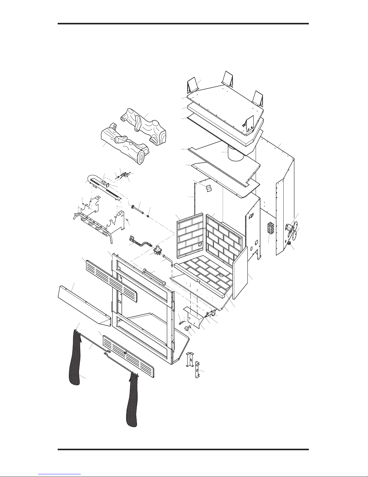
www.desatech.com
115254-01A
36
32
35
33
36
37
34
48
28
40
40
41
39
38
33
30
29
46
47
1
2
3
6
7
9
4
8
16
15
11
27
24
13
44
43
42
38
45
14
12
10
49
18
19
25
26
23
22
21
20
31
31
5
17
ILLUSTRATED PARTS BREAKDOWN
MANUAL MODELS
L32HN, L32LHN, L32HP, L32LHP, VL32HN, VL32LHN, VL32HP AND VL32LHP
Page 37

www.desatech.com
115254-01A 37
PARTS LIST
This list contains replaceable parts used in your firebox. When ordering parts, follow the instructions
listed under Replacement Parts on page 34 of this manual.
PART NUMBER
KEY L32HN L32HP L32LHN L32LHP
NO. VL32HN VL32HP VL32LHN VL32LHP DESCRIPTION QTY.
1 108441-01 108441-01 108441-01 108441-01 Screen 2
2 108701-01 108701-01 108701-01 108701-01 Screen Rod 2
3 11418 11418 11418 11418 Push-On Nut 2
4 108414-01 108414-01 108414-01 108414-01 Deflector Hood 1
5 108423-01 108423-01 — — Face Top Panel (Black) 1
— — 108423-02 108423-02 Louver Face Top Panel 1
6 115314-01 115314-01 — — Face Bottom Assembly 1
— — 115314-04 115314-04 Louver Face Bottom Assy 1
7 ** ** ** ** Face Weldment 1
8 106683-01 106683-01 106683-01 106683-01 Firebox Support Leg 2
9 108434-01 108434-01 108434-01 108434-01 Left Refractory 1
10 108430-01 108430-01 108430-01 108430-01 Rear Refractory 1
11 108432-01 108432-01 108432-01 108432-01 Right Refractory 1
12 115262-01 115262-01 115262-01 115262-01 Bottom Refractory 1
13 116024-01 116024-01 116024-01 116024-01 Valve Bracket 1
14 ** ** ** ** Firebox Bottom 1
15 ** ** ** ** Firebox Surround 1
16 20027 20027 20027 20027 Refractory Retainer 2
17 ** ** ** ** Firebox Top Insulation 1
18 ** ** ** ** Firebox Top 1
19 108415-01 108415-01 108415-01 108415-01 Starter Pipe Collar 1
20 ** ** ** ** Insulation Pan 1
21 108403-03 108403-03 108403-03 108403-03 Fireplace Top 1
22 20280 20280 20280 20280 Top Spacer 4
23 ** ** ** ** Fireplace Surround 1
24 24353 24353 24353 24353 Handy Box Assy 2
25 108654-01 108654-01 108654-01 108654-01 Gas Conduit Left and
Right Assy 2
26 21171 21171 21171 21171 Gas Knock-Out Cover 4
27 14123 14123 14123 14123 Strain Relief 1
28 14261 14261 14261 14261 Piezo Ignitor 1
29 14253 14253 14253 14253 Gas Line Flex w/Shut Off 1
30 098867-14 098867-10 098867-14 098867-10 Regulator 1
31 110397-01 110397-01 110397-01 110397-01 Two Piece Log Set 1
32 ** ** ** ** Painted Base Assembly 1
33 M11084-38 M11084-38 M11084-38 M11084-38 Hex Head Screw 2
34 116011-01 116011-01 116011-01 116011-01 Outlet Burner Tube 1
35 102963-01 102963-01 102963-01 102963-01 Burner 1
36 099056-20 099056-21 099056-20 099056-21 Burner Orifice Injector 1
37 102843-01 102843-01 102843-01 102843-01 Burner Clip 1
38 099387-05 099387-05 099387-05 099387-05 Pilot Tube 1
39 098249-01 098249-01 098249-01 098249-01 M5 Nut 2
40 098271-10 098271-10 098271-10 098271-10 Ignitor Cable 1
41 104285-01 104286-01 104285-01 104286-01 ODS Pilot 1
42 098276-01 098276-01 098276-01 098276-01 1/8" NPT Hex Head Plug 1
43 098508-01 098508-01 098508-01 098508-01 Valve Retainer Nut 1
44 098534-01 098534-01 098534-01 098534-01 Control Knob 1
45 102568-07 102568-08 102568-07 102568-08 Control Valve 1
46 116059-01 116059-01 116059-01 116059-01 Inlet Tube 1
47 111817-04 111817-04 111817-04 111817-04 Flexible Dormont T6-21
3
/8 1
48 115998-01 115998-01 115998-01 115998-01 3/8" Compression Union 1
49 108413-01 108413-01 108413-01 108413-01 Shield Firebox Top 1
PARTS AVAILABLE NOT SHOWN
100563-01 100563-01 100563-01 100563-01 Warning Label 1
101055-02 101055-02 101055-02 101055-02 Lighting Instruction Plate 1
100639-01 100639-01 100639-01 100639-01 Caution Decal 1
GA6060 GA6060 GA6060 GA6060 Lava Rock 1
** Part shown is not field replaceable.
Page 38

www.desatech.com
115254-01A
38
ILLUSTRATED PARTS BREAKDOWN
MANUAL MODELS
L36EN, L36LEN, L36EP, L36LEP, VL36EN, VL36LEN, VL36EP AND VL36LEP
27
45
47
37
35
32
36
41
41
29-1
29-2
41
29
30
34
33
31
41
39
46
34
40
44
1
2
3
4
8
11
12
13
14
20
23/24
22
19
21
18
17
15
50
49
10
51
53
52
5
48
9
7
6
16
25
26
43
42
46
28
Page 39

www.desatech.com
115254-01A 39
PARTS LIST
This list contains replaceable parts used in your firebox. When ordering parts, follow the instructions
listed under Replacement Parts on page 34 of this manual.
PART NUMBER
KEY L36EN L36LEN L36EP L36LEP
NO. VL36EN VL36LEN VL36EP VL36LEP DESCRIPTION QTY.
1 12116 12116 12116 12116 Screen 2
2 106691-01 106691-01 106691-01 106691-01 Screen Rod 2
3 11418 11418 11418 11418 Push-On Nut 2
4 107944-01 107944-01 107944-01 107944-01 Deflector Hood 1
5 106651-01 — 106651-01 Top Panel, Smooth 1
— 106684-01 — 106684-01 Top Panel 1
6 115314-02 — 115314-02 — Bottom Panel Assy, Smooth 1
— 115314-07 — 115314-07 Bottom Panel Assy 1
7 ** ** ** ** Face Weldment 1
8 106683-01 106683-01 106683-01 106683-01 Firebox Support Leg 2
9 ** ** ** ** Firebox Bottom 1
10 20027 20027 20027 20027 Refractory Retainer 2
11 ** ** ** ** Firebox Surround 1
12 ** ** ** ** Firebox Top Shield 1
13 ** ** ** ** Firebox Top 1
14 106687-01 106687-01 106687-01 106687-01 Damper Can Collar 1
15 ** ** ** ** Insulation Pan 1
16 ** ** ** ** Fireplace Top Insulation 1
17 ** ** ** ** Fireplace Top 1
18 20280 20280 20280 20280 Top Spacer 4
19 ** ** ** ** Fireplace Surround 1
20 24353 24353 24353 24353 Handy Box Assy 2
21 14123 14123 14123 14123 Strain Relief 1
22 21171 21171 21171 21171 Gas Knock-Out Cover 4
23 21379 21379 21379 21379 Gas Conduit 1
24 21380 21380 21380 21380 Gas Conduit 1
25 116024-01 116024-01 116024-01 116024-01 Valve Bracket 1
26 14261 14261 14261 14261 Piezo Ignitor 1
27 14253 14253 14253 14253 Gas Line Flex w/Shut Off 1
28 102568-05 102568-05 102568-06 102568-06 Gas Control Valve 1
29 101330-05 101330-05 101330-05 101330-05 Front Burner Assembly 1
29-1 101008-01 101008-01 101008-01 101008-01 Crossover Burner Bracket 1
29-2 101007-01 101007-01 101007-01 101007-01 Crossover Burner 1
30 109824-02 109824-02 109824-02 109824-02 Rear Burner Assembly 1
31 ** ** ** ** Grate Assembly 1
32 115401-01 115401-01 115401-01 115401-01 Base Pan 1
33 108138-01 108138-01 108138-01 108138-01 Saddle Bracket 2
34 M11084-38 M11084-38 M11084-38 M11084-38 Screw 4
35 101004-11 101004-11 101004-01 101004-01 Rear Burner Injector 1
36 101004-08 101004-08 101004-02 101004-02 Front Burner Injector 1
37 116009-01 116009-01 116009-01 116004-01 Outlet Burner Tube 1
38 M11084-26 M11084-26 M11084-26 M11084-26 Screw 4
39 103042-01 103042-01 099059-02 099059-02 ODS Pilot 1
40 098271-01 098271-01 098271-01 098271-01 Ignitor Cable 1
41 098249-01 098249-01 098249-01 098249-01 Nut 8
42 098276-01 098276-01 098276-01 098276-01 1/8" NPT Hex Head Plug 1
43 098508-01 098508-01 098508-01 098508-01 Valve Retainer Nut 1
44 098534-01 098534-01 098534-01 098534-01 Control Knob 1
45 098867-09 098867-09 098867-10 098867-10 Regulator 1
46 099387-05 099387-05 099387-05 099387-05 Pilot Tube 1
47 116059-01 116059-01 116059-01 116059-01 Inlet Tube 1
48 See page 42 See page 42 See page 42 See page 42 Left Refractory 1
49 See page 42 See page 42 See page 42 See page 42 Right Refractory 1
50 See page 42 See page 42 See page 42 See page 42 Rear Refractory 1
51 See page 42 See page 42 See page 42 See page 42 Bottom Refractory 1
52 111817-04 111817-04 111817-04 111817-04 Flexible Dormont T6-21
3
/8 1
53 115998-01 115998-01 115998-01 115998-01 3/8" Compression Union 1
PARTS AVAILABLE NOT SHOWN
100563-01 100563-01 100563-01 100563-01 Warning Label 1
103877-01 103877-01 103877-01 103877-01 Lighting Instruction Plate 1
100639-01 100639-01 100639-01 100639-01 Caution Decal 1
GA6060 GA6060 GA6060 GA6060 Lava Rock 1
** Part shown is not field replaceable.
Page 40

www.desatech.com
115254-01A
40
27
35
40
32
34
34
51
42
34
41
50
31
43
38
39
37
33
41
25
1
2
3
4
8
11
12
13
14
20
23/24
22
19
21
18
17
15
48
47
10
49
5
46
9
34
29
36
28
30
45
44
7
6
16
26
ILLUSTRATED PARTS BREAKDOWN
REMOTE-READY MODELS
L36ZNR, L36LZNR, L36ZPR, L36LZPR, L42ZNR, L42LZNR, L42ZPR,
L42LZPR, VL36ZNR, VL36LZNR, VL36ZPR, VL36LZPR, VL42ZNR,
VL42LZNR, VL42ZPR AND VL42LZPR
Page 41

www.desatech.com
115254-01A 41
PARTS LIST
This list contains replaceable parts used in your firebox. When ordering parts, follow the instructions
listed under Replacement Parts on page 34 of this manual.
PART NUMBER
KEY (V)L36ZNR/PR (V)L42ZNR/PR
NO. (V)L36LZNR/PR (V)L42LZNR/PR DESCRIPTION QTY.
1 12116 12116 Screen 2
2 106691-01 106691-01 Screen Rod 2
3 11418 11418 Push-On Nut 2
4 107944-01 107944-01 Deflector Hood 1
5 115312-01 115312-03 Top Rolled Louver Panel 1
6 115313-01 115313-03 Bottom Rolled Louver Panel 1
7 ** ** Face Weldment 1
8 106683-01 106683-01 Firebox Support Leg 2
9 ** ** Firebox Bottom 1
10 20027 20027 Refractory Retainer 2
11 ** ** Firebox Surround 1
12 ** ** Firebox Top Shield 1
13 ** ** Firebox Top 1
14 106687-01 106687-01 Damper Can Collar 1
15 ** ** Insulation Pan 1
16 ** ** Fireplace Top Insulation 1
17 ** ** Fireplace Top 1
18 20280 20280 Top Spacer 4
19 ** ** Fireplace Surround 1
20 24353 24353 Handy Box Assy 2
21 14123 14123 Strain Relief 1
22 21171 21171 Gas Knock-Out Cover 4
23 21379 21379 Gas Conduit 1
24 21380 21380 Gas Conduit 1
25 107741-04 107741-04 Valve Bracket 1
26 14261 14261 Piezo Ignitor 1
27 14253 14253 Gas Line Flex w/Shut Off 1
28 103781-01 103781-01 Gas Control Valve (NG) 1
103781-02 103781-02 Gas Control Valve (LP) 1
29 108005-01 108005-01 Wire Harness 1
30 108005-02 108005-02 Wire Harness 1
31 112465-02 112465-02 Front Ramp Burner 1
32 113242-02 113242-03 Rear Ramo Burner 1
33 ** ** Grate Assembly 1
34 M11084-26 M11084-26 Screw 12
35 099918-02 099918-02 Pilot Regulator (NG Only) 1
36 099387-12 099387-12 Pilot Tube (NG) 1
099387-14 099387-14 Pilot Tube (NG) 1
099387-03 099387-03 Pilot Tube (LP) 1
37 101004-08 101004-08 Front Burner Injector (NG) 1
101004-06 101004-06 Front Burner Injector (LP) 1
38 101004-04 101004-04 Rear Burner Injector (NG) 1
101004-02 101004-02 Rear Burner Injector (LP) 1
39 112708-01 112708-01 Burner Tube 1
40 098264-02 098264-02 Male Fitting 1
41 098271-01 098271-01 Ignitor Cable 1
42 103779-01 103779-01 ODS Pilot (NG) 1
103778-01 103778-01 ODS Pilot (LP) 1
43 098249-01 098249-01 Nut 2
44 103587-01 103587-01 Switch Plate 1
45 14579 14579 Switch 1
46 See Page 43 See Page 43 Left Refractory 1
47 See Page 43 See Page 43 Right Refractory 1
48 See Page 43 See Page 43 Rear Refractory 1
49 See Page 43 See Page 43 Bottom Refractory 1
50 112782-02 112782-02 Air Deflector Bracket 1
51 112713-03 112713-03 Pilot Bracket 1
PARTS AVAILABLE NOT SHOWN
100563-01 100563-01 Warning Label 1
103877-01 103877-01 Lighting Instruction Plate 1
100639-01 100639-01 Caution Decal 1
GA6060 GA6060 Lava Rock 1
** Part shown is not field replaceable.
Page 42

www.desatech.com
115254-01A
42
ILLUSTRATED PARTS BREAKDOWN AND PARTS LIST
LOG SETS FOR MODELS L36EN, L36LEN, L36EP, L36LEP, VL36EN,
VL36LEN, VL36EP AND VL36LEP
5
4
3
2
1
KEY LOG
NO. PART NUMBERS DESCRIPTION QTY
1 110314-01 Front Left Log 1
2 110314-02 Front Right Log 1
3 110314-03 Middle Log 1
4 110314-04 Rear Log 1
5 110314-05 Crossover Log 1
REFRACTORY PART NUMBERS FROM PAGE 39
KEY L36EN L36LEN VL36EN VL36LEN
NO. L36EP L36LEP VL36EP VL36LEP DESCRIPTION QTY.
48 106658-02 106658-02 106658-01 106658-01 Left Refractory 1
49 106659-02 106659-02 106659-01 106659-01 Right Refractory 1
50 106660-02 106660-02 106660-01 106660-01 Rear Refractory 1
51 114999-02 114999-02 114999-01 114999-01 Bottom Refractory 1
Page 43
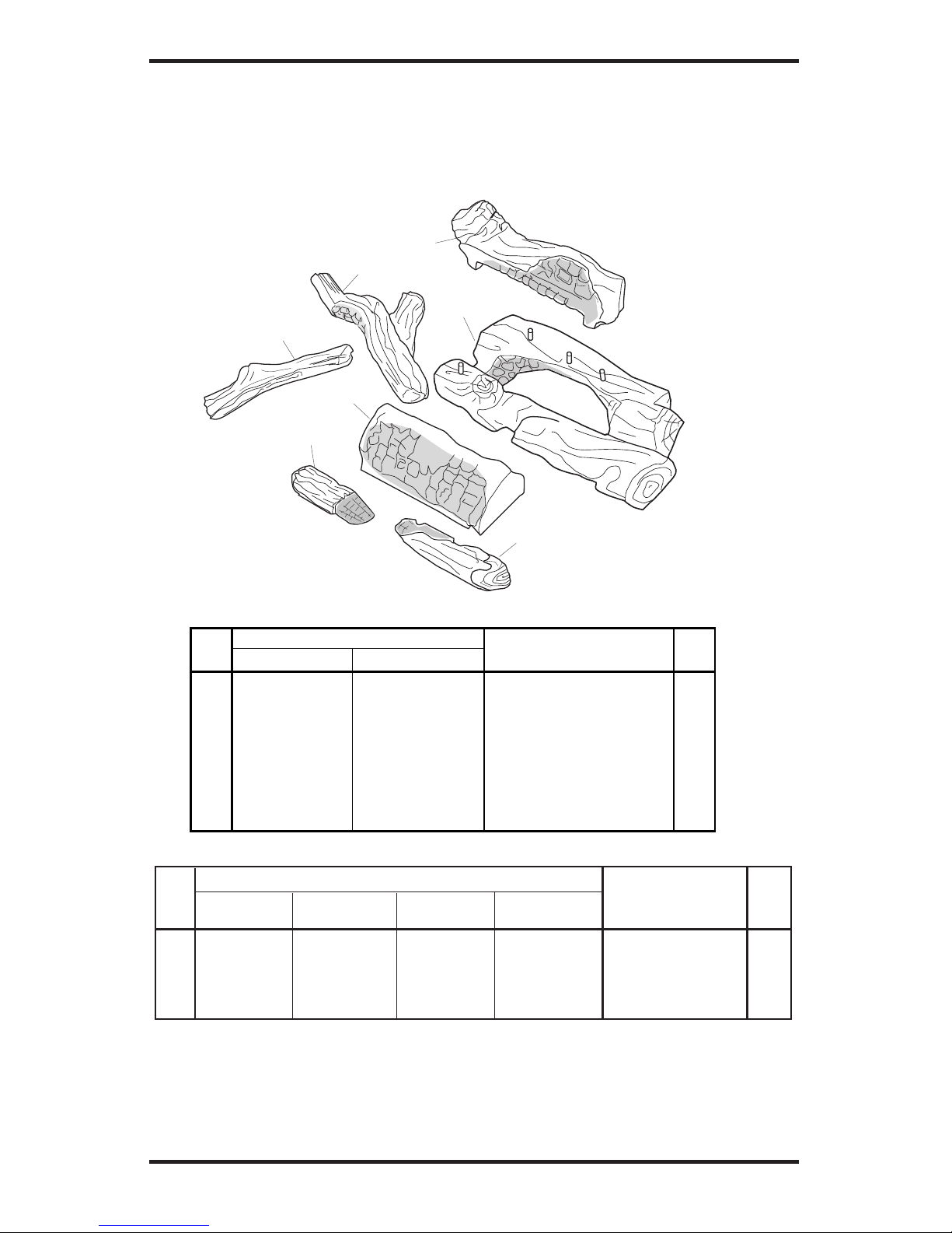
www.desatech.com
115254-01A 43
ILLUSTRATED PARTS BREAKDOWN AND PARTS LIST
LOG SETS FOR MODELS L36ZNR, L36LZNR, L36ZPR, L36LZPR, VL36ZNR,
VL36LZNR, VL36ZPR, VL36LZPR, L42ZNR, L42LZNR, L42ZPR, L42LZPR,
VL42ZNR, L42LZNR, VL42ZPR AND VL42LZPR
KEY LOG PART NUMBERS
NO. (V)L36 MODELS (V)L42 MODELS DESCRIPTION QTY
1 114984-01 114984-08 Middle Log 1
2 114984-02 114984-09 Left Top Log 1
3 114984-03 114984-10 Right Top Log 1
4 114984-04 114984-11 Rear Log 1
5 114984-05 114984-05 Left Control Cover Log 1
6 114984-06 114984-06 Right Control Cover Log 1
7 114984-07 114984-07 Ember Bed 1
1
4
2
3
5
6
7
REFRACTORY PART NUMBERS FROM PAGE 41
KEY L36ZNR/PR VL36ZNR/PR L42ZNR/PR VL42ZNR/PR
NO. L36LZNR/PR VL36LZNR/PR L42LZNR/PR VL42LZNR/PR DESCRIPTION QTY.
46 106658-02 106658-01 107812-02 107812-01 Left Refractory 1
47 106659-02 106659-01 107814-02 107814-01 Right Refractory 1
48 106660-02 106660-01 107816-02 107816-01 Rear Refractory 1
49 114999-02 114999-01 115263-02 115263-01 Bottom Refractory 1
Page 44

LIMITED WARRANTY
VENT-FREE FIREPLACE
DESA warrants this product to be free from defects in materials and components for four (4) years from the date
of first purchase, provided that the product has been properly installed, operated and maintained in accordance
with all applicable instructions. To make a claim under this warranty the Bill of Sale or cancelled check must
be presented.
This warranty is extended only to the original retail purchaser. This warranty covers the cost of part(s) required to
restore this heater to proper operating condition and an allowance for labor when provided by a DESA Authorized
Service Center. Warranty part(s) MUST be obtained through authorized dealers of this product and/or DESA who
will provide original factory replacement parts. Failure to use original factory replacement parts voids this warranty.
The heater MUST be installed by a qualified installer in accordance with all local codes and instructions furnished
with the unit.
This warranty does not apply to parts that are not in original condition because of normal wear and tear or parts
that fail or become damaged as a result of misuse, accidents, lack of proper maintenance or defects caused by
improper installation. As with all concrete liners, this liner may develop slight cracks when exposed to heat. This
cracking is considered normal. Travel, diagnostic cost, labor, transportation and any and all such other costs related
to repairing a defective heater will be the responsibility of the owner.
TO THE FULL EXTENT ALLOWED BY THE LAW OF THE JURISDICTION THAT GOVERNS THE SALE OF
THE PRODUCT; THIS EXPRESS WARRANTY EXCLUDES ANY AND ALL OTHER EXPRESSED WARRAN
TIES AND LIMITS THE DURATION OF ANY AND ALL IMPLIED WARRANTIES, INCLUDING WARRANTIES
OF MERCHANTABILITY AND FITNESS FOR A PARTICULAR PURPOSE TO FOUR (4) YEARS ON ALL
COMPONENTS FROM THE DATE OF FIRST PURCHASE; AND DESAʼS LIABILITY IS HEREBY LIMITED
TO THE PURCHASE PRICE OF THE PRODUCT AND DESA SHALL NOT BE LIABLE FOR ANY OTHER
DAMAGES WHATSOEVER INCLUDING INDIRECT, INCIDENTAL OR CONSEQUENTIAL DAMAGES.
Some states do not allow a limitation on how long an implied warranty lasts or an exclusion or limitation of
incidental or consequential damages, so the above limitation on implied warranties or exclusion or limitation on
damages may not apply to you.
This warranty gives you specific legal rights and you may also have other rights that vary from state to state.
For information about this warranty write:
2701 Industrial Drive
P.O. Box 90004
Bowling Green, KY 42102-9004
www.desatech.com
115254-01
Rev. A
11/04
NOT A UPC
WARRANTY INFORMATION
KEEP THIS WARRANTY
Model
Serial No.
Date Purchased
115254 01
Always specify model and serial numbers when communicating with the factory.
We reserve the right to amend these specifications at any time without notice. The only warranty applicable is our
standard written warranty. We make no other warranty, expressed or implied.
 Loading...