

Page 1
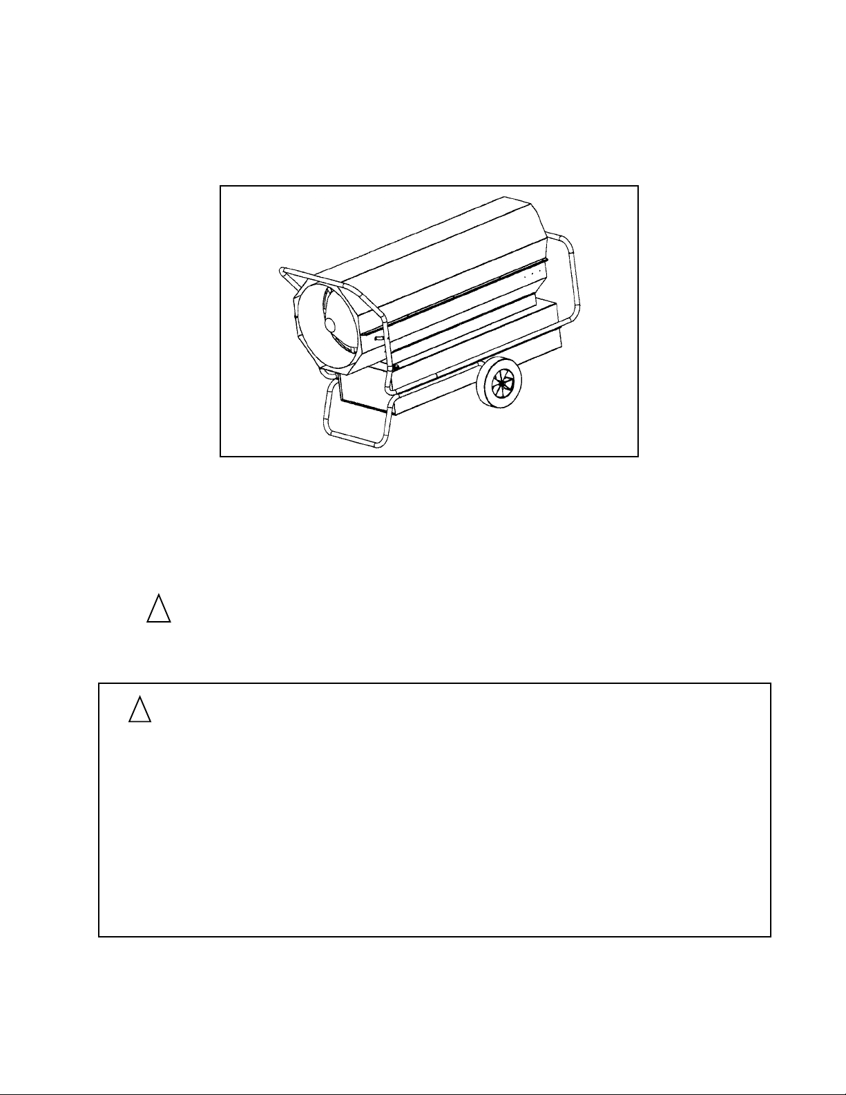
FORCED AIR HIGH PRESSURE KEROSENE
CONSTRUCTION HEATERS
INSTRUCTIONS AND PARTS LIST
MODELS
350,000 BTU/HR 620,000 BTU/HR
K350-FA K650-FA
SPC-K350 SPC-K650
!
YOUR SAFETY IS IMPORTANT TO YOU AND TO OTHERS,
SO PLEASE READ THESE INSTRUCTIONS BEFORE YOU
OPERATE THIS HEATER.
GENERAL HAZARD WARNING:
!
FAILURE TO COMPLY WITH THE PRECAUTIONS AND INSTRUCTIONS PROVIDED WITH
THIS HEATER, CAN RESULT IN DEATH, SERIOUS BODILY INJURY AND PROPERTY
LOSS OR DAMAGE FROM HAZARDS OF FIRE, EXPLOSION, BURN, ASPHYXIATION,
CARBON MONOXIDE POISONING, AND/OR ELECTRICAL SHOCK.
ONLY PERSONS WHO CAN UNDERSTAND AND FOLLOW THE INSTRUCTIONS SHOULD
USE OR SERVICE THIS HEATER.
IF YOU NEED ASSISTANCE OR HEATER INFORMATION SUCH AS AN INSTRUCTIONS
MANUAL, LABELS, ETC. CONTACT THE MANUFACTURER.
RETAIN THESE INSTRUCTIONS FOR FUTURE REFERENCE
7993C
September 2001
Page 2
SAFETY INSTRUCTIONS
This is an oil, direct-fired, forced air heater. It's intended use is primarily temporary heating of buildings under construction, alternation or repair.
!
NOT FOR HOME OR RECREATIONAL VEHICLE USE
WARNING
GENERAL PRECAUTIONS
This is an oil direct-fired forced air heater.
Direct-Fired means that all of the combustion products
enter the heated space. Even though this heater operates
very close to 100 percent combustion efficiency, it still
produces small amounts of carbon monoxide. Carbon
monoxide (called CO) is toxic. We can tolerate small
amounts but not a lot. OSHA says that 50 parts per million
(ppm) in the air we breathe is okay if it does not average more
than that during an 8 hour working period. Regardless, CO
can build up in a heated space and failure to provide
adequate ventilation could result in death. The symptoms
of inadequate ventilation are:
headache
dizziness
burning eyes and nose
nausea
dry mouth or sore throat
So be sure to follow requirements about ventilation in these
operating instructions.
Forced Air means that a blower or fan pushes the air through
the heater. Proper combustion depends upon this air flow;
therefore, the heater must not be revised, modified, or
operated with parts removed or missing. Likewise, safety
systems must not be circumvented or modified in order to
operate the heater.
When the heater is to be operated in the presence of other
people the user is responsible for properly acquainting
those present with the safety precautions and instructions, and of the hazards involved.
SAFETY PRECAUTIONS
1. Check the heater thoroughly for damage. Never operate a damaged heater.
2. Never modify the heater or operate the heater if it has
been modified from its original condition.
3. Use only Kerosene or #1 fuel oil. Never use gasoline,
naphtha, paint thinner, alcohol or other fuels of any
kind.
4. For indoor use only.
5. Use only in well ventilated areas. Provide at least 9 sq.
ft. (K350 - 5 sq. ft.) of opening near the floor and 9 sq. ft.
(K350 - 5 sq. ft.) of opening near the ceiling.
6. Always keep combustibles, like paper and wood at
least 10 ft. from the heater outlet and 4 ft. from the top,
sides and inlet. Locate 10 ft. from canvas or plastic
coverings and secure them to prevent flapping or
movement. This heater produces carbon monoxide,
which is listed by the State of California as a reproductive toxin under proposition 65.
7. Never use in places where exposure to flammable
vapors or high dust content is possible. This includes
gasoline, paint thinners, solvents, coal-dust, sawdust,
etc.
8. Install the heater such that it is not directly exposed to
water spray, rain and/or dripping water or wind.
9. Never use in areas normally for habitation andor where
children may be present.
10. Operate only on a stable, level surface.
11. Do not use with ductwork. Do not restrict inlet orexit.
12. Use only the electrical power specified.
13. Use only a properly grounded 3 wire extension cord.
14. Unplug heater from electrical supply when not in use.
15. Do not move, handle or service while hot or burning.
16. Heater is equipped with a thermostat, and may start at
any time.
17. Use only in accordance with State and Federal
ordinances.
Page 2
!
WARNING: FIRE, BURN, INHALATION, AND EXPLOSIOIN HAZARD.
KEEP SOLID COMBUSTIBLES, SUCH AS BUILDING MATERIALS, PAPER
OR CARDBOARD, A SAFE DISTANCE AWAY FROM THE HEATER AS RECOMMENDED BY THE INSTRUCTIONS. NEVER USE THE HEATER IN SPACES
WHICH DO OR MAY CONTAIN VOLATILE OR AIRBORNE COMBUSTIBLES,
OR PRODUCTS SUCH AS GASOLINE, SOLVENTS, PAINT THINNER, DUST
PARTICLES OR UNKNOWN CHEMICALS.
Page 3

OPERATING INSTRUCTIONS
FUELING
1. Only qualified personnel familiar with these
instructions and applicable local, state, and federal
regulations and codes may fuel this heater.
2. Use only kerosene or #1 fuel oil in this heater.
3. All flames shall be extinguished and the heater
allowed to cool, before fueling.
4. When the heater is removed from service for
fueling, all lines and connections in the fuel system
shall be inspected and any repairs made before
returning heater to operation.
5. The fuel cap gasket and vent hole shall be inspected to insure that they are clear and clean from
contaminates
6. Only the fuel in the internal tank may be stored in
the heated building.
7. In the absents of local regulations and codes bulk
fuel storage must be a minimum of 25 feet from the
heaters, or other sources of ignition.
8. All fuel must pass through the tank inlet screen to
remove foreign material before it enters the tank.
9. CAUTION: Make sure that the fuel used is free of
water.
10. Never operate a heater that does not have a factory
purchased vented fuel cap.
UNPACKING
1. Remove all protective material, which may have
been applied to the heater for shipment.
2. Remove the heater from carton or crate.
3. Check the heater for possible shipping damage. If
any is found immediately notify the dealer from
whom you purchased the heater.
OPERATION
TO FUEL
IMPORTANT: Be sure the fuel storage container is
clean. Foreign matter such as rust, dirt, or water will
cause the flame control to shut down heater. Foreign
matter will also require more frequent cleaning of the
fuel system.
Fill the fuel tank with clean kerosene, No. 1 fuel oil or No. 1
diesel fuel only. Do not use heavy fuels such as No. 2 fuel
oil or No. 2 diesel, because it will build up carbon in
combustion chamber and clog fuel filters. Kerosene is
recommended for use when the temperature drops below
zero degrees fahrenheit (-18
weather, condensation may develop in the tank and it is
recommended that a tablespoon of de-icer be added for
each gallon (4 liters) of fuel in the tank.
When filling the heater use at least 2 gallons (8 liters) of fuel.
Be sure heater is level and do not overfill. Use a funnel or
can with a long fill spout.
WARNING: To avoid fire, wipe up any spilled fuel immediately.
o
Celsius). In extremely cold
TO LOCATE
WARNING: To avoid fire, place the unit in a level location
away from volatile substances and at a safe distance from
combustible materials. Adequate ventilation is essential.
Refer to the SAFETY PRECAUTION page for advice on
adequate ventilation.
TO START
1. Turn thermostat knob to highest setting. Push reset
button.
2. Heater will start when plug heater into electrical
power.
WARNING: Use only a three-prong, grounded
extension cord.
3. Set thermostat to desired temperature. Heater will
cycle on / off to maintain temperature
TO STOP
1. Set thermostat to lowest temperature setting.
2. Never unplug heater until purge / cool down cycle is
complete.
TO RESTART
1. Wait 5 minutes.
2. Push reset button
3. If heater continues to cycle off on flame safety, see a
service person.
STORAGE AND TRANSPORTING
IMPORTANT: Before filling fuel tank for the first time or
after extended storage periods drain the fuel tank of any
moisture or condensation.
Follow instructions under safety precautions before filling.
CAUTION: Hot while in operation. Do not touch.
Keep children, clothing and combustibles away.
WARNING: NEVER TRANSPORT THE HEATER WITH
FUEL IN THE INTERNAL TANK.
1. Drain the fuel filters, fuel lines, and pump.
2. Drain the fuel from the tank.
3. If fuel drained from the tank is dirty, flush tank with
clean fuel.
4. Store heater in a dry location free from fumes or dust.
Page 3
Page 4

SERVICING
MAINTENANCE
A hazardous condition may result if a heater is used that
has been modified or is not functioning properly. When the
heater is working properly:
o The flame is contained within the heater with
perhaps some yellow tippng from the exit cone.
o There is no strong disagreeable odor, eye
burning or other physical discomfort.
o There is no smoke or soot internal or external
to the heater.
o There are no unplanned or unexplained
shutdowns of the heater.
The parts list and wiring diagram show the heater as it
was constructed. Do not use a heater which is different from
that shown. Heater performance is effected by pressure
setting. If there is any uncertainty about the pressure
setting, have it checked.
A heater which is not working right must be repaired, but
only by a trained, experienced service person. Contact the
factory for the service center closest to you, phone 909/981534 3.
You may also obtain in warranty or out of warranty service
by returning the product freight prepaid to:
Scheu Products Company
8855 Baker Avenue
Rancho Cucamonga, CA 91730
Contact customer service for Return Goods Authorization Number.
In warranty products returned to the Service Department
will be repaired with no charge for either parts or labor and
will be returned to you freight prepaid. Please include a brief
statement indicating date and place of purchase and the
nature of the problem, and proof of purchase.
Out of warranty products returned to the Service Department will be repaired with a charge for parts and labor and
will be returned to you freight collect.
WARNING: To prevent personal injury, unplug the heater
from electrical source before servicing.
For maximum efficiency and trouble-free service make the
following periodic maintenance, cleaning and inspections.
DAILY SCHEDULE
1. GENERAL. Make general visual inspection of heater for
loose or damaged parts. Check nuts and bolts to insure
against looseness caused by vibration or rough handling. Damaged parts should be repaired or replaced
before using heater again. Check heater operation to be
sure it is operating normally.
2. Check for foreign matter in the fuel when filling the tank.
If any is found flush the tank.
200 HOUR SCHEDULE
Flush tank using 2-3 gal of fresh kerosene.
1.
2. Clean the fuel screens in the tank or replace if
needed.
3. Clean the pump filter element.
4. Remove, inspect and clean the ignition electrode.
5. Clean the glass portion of the cad cell with a soft dry
cloth.
6. Clean the heater at least twice a season (more often
in dusty conditions). Remove accumulated dust
from the fan, burner, and deflector fins.
ANNUAL SCHEDULE
1. Check and adjust the pump pressure to the proper
setting as specified on the ratings label.
MODELS
Input Rating, BTU/hr
Type of Fuel
Fuel Consumption, Gal/Hr
Pump pressure, psig
Fuel Tank Capacity, gals.
Electrical Input
Minimum Operating
Fan Motor
Ignition
Spark Generator
Electrode
Dry Weight (#)
Wet Weight (#)
Page 4
HEATER SPECIFICATIONS
K350
350,000
Kerosene or #1 Fuel Oil Only
2.5
100
30
115V, 60Hz, 10, 9 amps
100V
1750 rpm, 1500 cfm
Over Surface, continuous
Ignitor, 13k secondary
Single post electrode
195
405
K650
620,000
Kerosene or #1 Fuel Oil Only
4.3
110
49
115V, 60Hz, 10, 11 amps
100V
3450 rpm, 3000 cfm
Over Surface, continuous
ignitor, 13k secondary
Single post electrode
300
643
Page 5
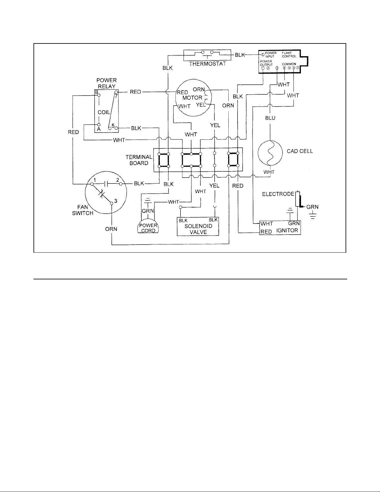
WIRING CHART
Wiring Connection Table for the K350 and K650
Part No. Color From To Us e
White Power Cord Terminal Board 5 Common
Black Power Cord Terminal Board 3 Line
Black Thermostat Terminal Board 3 Line
White Thermostat Flame Control Line In (Circuit Breaker)
Re d Igniter Terminal Board 2
Black Igniter Flame Control Term. 4 Common
1040 Black Flame Control Term. 1 (line out) Terminal Board 2
1040 Black Power Relay Term. 5 (center term) Terminal Board 3 Line
1153 White Flame Control term. 5 (common) Terminal Board 5 Common
1153 White Power Relay Term. A (coil lowest left) Terminal Board 5 Common
2053 White Fuel Valve Terminal Board 5 Common
2053 White Cad Cell White Wire Terminal Board 5 Common
2054 Yellow Fuel Valve Terminal Board 1
2058 Orange Fan Switch Term. 3 (solitary term.) Terminal Board 2
2056 Black Fan Switch Term. 2 Terminal Board 3
2055 Blue Cad Cell Blue Wire Flame Control Term. 3
2057 Red Fan Switch Term. 1 Power Relay Term. B (coil right)
2059 Green Combustion Chamber Ground Ground Screw
1799 Green Igniter High Voltage Ground Ground Screw
Green Power Cord Ground Screw
Green Thermostat Ground Screw
Yellow Motor Terminal Board 1
Orange Motor Terminal Board 2
Red Motor Power Relay Term. (top left)
White Motor Terminal Board 5 Common
2049 Orange Igniter High Voltage Out Electrode
Page 5
Page 6
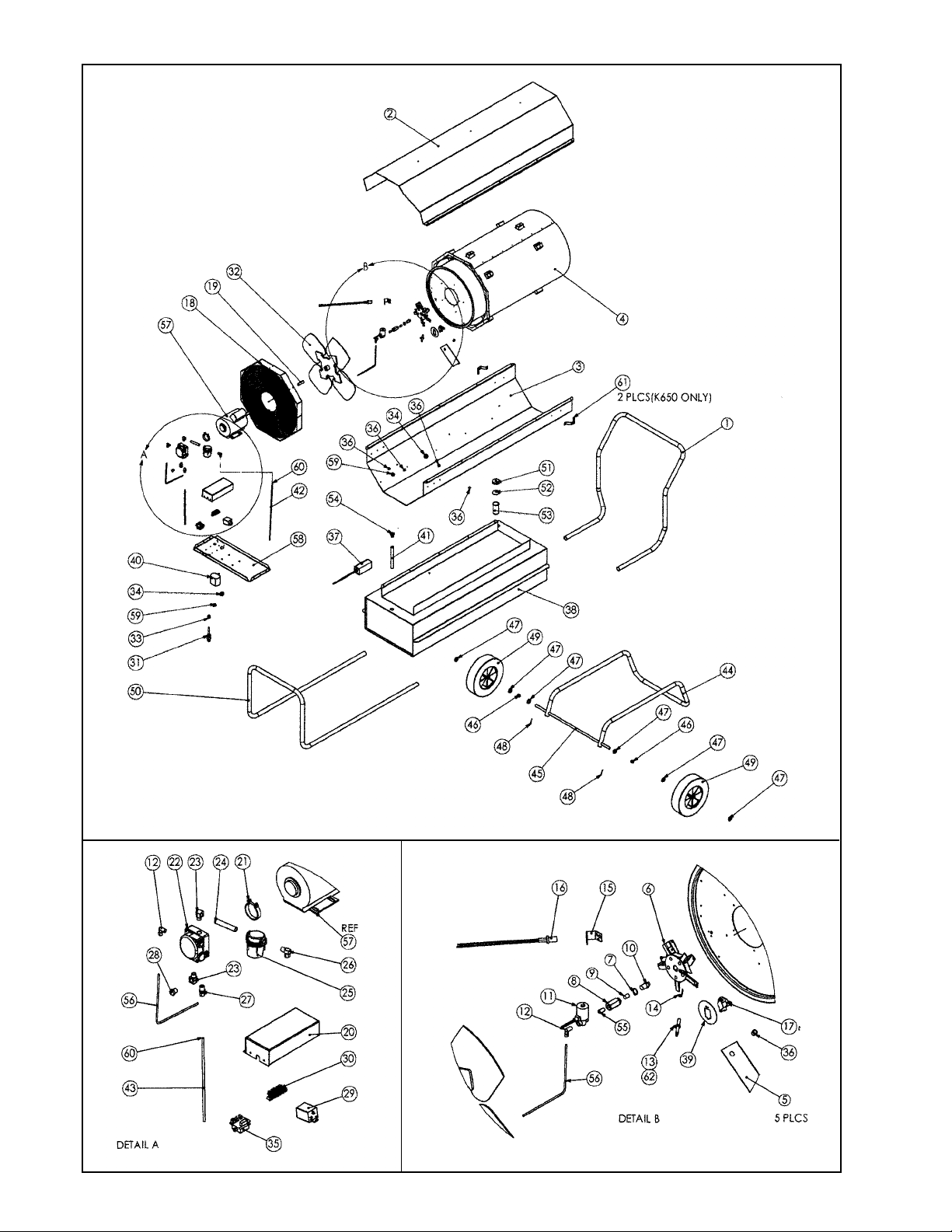
K Heaters
Page 7
Page 7
INSTRUCTIONS FOR ORDERING PARTS - All parts
orders must show heater Model No., Item No., Part
No. and Description. We recommend that only parts
supplied by the manufacturer be used on this unit. A
locally purchased part may appear to be identical,
although in reality it might endanger the heater or the
persons operating the heater.
High Pressure Kerosene Heaters Parts List
The heater should be serviced only by a trained, experienced service person.
Read the section on "Servicing" before ordering parts.
For parts order, call (909) 981-5343.
Item Part No. Part No. Description Qty.
K350 K650
1 4135 4126 Handle 1
2 4118 4074 Upper shell 1
3 2066 2042 Lower shell 1
4 2033 2020 Comb. chamber and shield 1
5 4106 4056 Air deflector 5
6 2025 2025 Burner head assembly 1
7 7429 7429 Retaining ring 1
8 4064 4064 Adapter, nozzle 1
9 4100 4100 Flow straightner plug 1
10 7950 7945 Nozzle 1
11 2061 2061 Solenoid valve 1
12 7958 7958 Fitting, male elbow 1
13 7788 7788 Electrode 1
14 4058 4058 Electrode ground 1
15 4122 4070 Cad cell mounting bracket 1
16 2151 2151 Cad cell sensor 1
17 7949 7949 Fan switch 1
18 2034 2021 Fan guard/grille 1
19 4080 4080 Fan spacer 1
20 4150 4150 Controls cover 1
21 7943 7943 Clamp, motor/pump 1
22 7941 7941 Pump 1
23 6142 6142 Fitting, elbow 2
24 7957 7957 Fitting, nipple 3" 1
25 7942 7942 Filter, pump inlet 1
26 7979 7979 Fitting, male elbow 1
27 7980 7980 Fitting, male connector 1
28 7981 7981 Fitting, male plug 1
29 7944 7944 Relay, power 1
30 4151 4151 Terminal board 1
31 1036 1036 Power cord 1
32 7954 7940 Fan 1
33 6223 6223 Bushing, strain relief 1
34 7424 7424 Bushing, snap 1" 2
35 6863 6863 Flame control 1
36 6224 6224 Snap bushing, 1/2" 5
37 2038 2038 Thermostat assembly 1
38 2035 2022 Tank assembly 1
39 4152 4152 Shield, fan swtich 1
40 2138 2138 Ignitor assembly 1
41 7963 7947 Filter tank outlet 1
42 4224 4148 Tube pump inlet 1
43 4225 4149 Tube return 1
44 4136 4127 Heater support 1
Item Part No. Part No. Description Qty.
K350 K650
45 4130 4130 Axle 1
46 7959 7959 Spacer wheel 2
47 7960 7960 Washer 6
48 7955 7955 Cotter pin 2
49 7951 7951 Wheel, 12" Dia. 2
50 4137 4128 Guard 1
51 7803 7803 Fuel cap 1
52 3994 3994 Gasket, fuel cap 1
53 7946 7946 Filter tank inlet 1
54 7994 7994 Grommet, fuel tank outlet 1
55 8066 8066 Fitting, nipple 1/8 x close 1
56 2037 2024 Fuel tube 1
57 7939 7939 Motor 1
58 4109 4077 Motor support 1
59 7158 7158 Bushing, snap 3/4" 1
60 7982 7982 Fitting, tube insert 2
61 4129 Bracket, handle mounting 2
62 6037 6037 Nut, hex cap 10-24 blk 1
* 1040 1040 Wire assembly, black 2
* 1153 1153 Wire assembly, white 2
* 1799 1799 Wire assembly, green 1
* 2051 2051 Wire harness 1
* 2053 2053 Wire assembly, white 2
* 2054 2054 Wire assemby, yellow 1
* 2055 2055 Wire assembly, blue 1
* 2056 2056 Wire assembly, black 1
* 2057 2057 Wire assembly, red 1
* 2058 2058 Wire assembly, orange 1
* 2059 2059 Wire assembly, green 1
* 4147 4147 Sleeving, pvc 1
* 6080 6080 Wire tie 4
* 7990 7984 Label, Model 1
* 7985 7985 Label, operating instructions 1
* 6410 6410 Label, warning thermostat 1
* 7348 7348 Label, Prop. 65 1
* 6910 6910 Label, fuel warning 1
* 7986 7986 Label, pump water warning 1
* 7987 7987 Label, thermostat oper. 1
* 7991 7989 Label, pump pressure 1
* 8005 8005 Label, pump operating 1
* 7732 7732 Label, Logo 2
* 7993 7993 Manual, operating instr. 1
* 2049 2049 Ignition Wire Assembly 1
* 3705 3705 Igniter Mounting Bracket 1
Page 6
* Not shown on exploded view
Page 8

SCHEU PRODUCTS COMPANY, INCORPORATED
Mail: P.O. Box 250, Upland, CA 91785
Plant: 8855 Baker Ave., Rancho Cucamonga, CA 91730
Telephone: 909/981-5343
 Loading...