


DNV25NB
DYNAVENT
WINDOW WALL FURNACE
DIRECT-VENT NATURAL GAS HEATER
OWNER’S OPERATION AND INSTALLATION MANUAL
DNV25NB
DNV40NB
50 60 70 80 90
SOLID STATE IGNITION
50 60 70 80 90
25,000 and 40,000 BTU/Hr “B” Model Furnaces
WARNING: If the information in these instructions is not
followed exactly, a fire or explosion may result causing
property damage, personal injury, or loss of life.
FOR YOUR SAFETY
Do not store or use gasoline or other flammable vapors
and liquids in the vicinity of this or any other appliance.
FOR YOUR SAFETY
WHAT TO DO IF YOU SMELL GAS
• Do not try to light any appliance.
• Do not touch any electrical switch.
• Do not use any phone in your building.
• Immediately call your gas supplier from a neighbor’s
phone. Follow the gas supplier’s instructions.
• If you cannot reach your gas supplier, call the fire
department.
WARNING: Improper installation, adjustment,
alteration, service, or
maintenance can cause
injury or property damage. Refer to this manual
for correct installation
and operational procedures. For assistance or
additional information
consult a qualified installer, service agency,
or the gas supplier.
— Installation and service must be performed
by a qualified installer,
service agency, or the
gas supplier.
This appliance may be installed in an aftermarket*, permanently located, manufactured (mobile) home, where not prohibited by local codes.
This appliance is only for use with the type of gas indicated on the rating plate. This
appliance is not convertible for use with other gases.
* Aftermarket: Completion of sale, not for purpose of resale, from the manufacturer
Save this manual for future reference.
®
DYNAVENT
DIRECT-VENT NATURAL GAS HEATER
SAFETY
INFORMATION
WARNINGS
IMPORTANT: Read this owner’s
manual carefully and completely
before trying to assemble, operate,
or service this furnace. Improper
use of this furnace can cause serious injury or death from burns, fire,
explosion, electrical shock, and
carbon monoxide poisoning.
DANGER: Carbon monoxide
poisoning may lead to death!
Carbon Monoxide Poisoning: Early signs of
carbon monoxide poisoning resemble the flu,
with headaches, dizziness, and/or nausea. If
you have these signs, the furnace may not be
working properly. Get fresh air at once! Have
furnace serviced. Some people are more affected by carbon monoxide than others. These
include pregnant women, people with heart or
lung disease or anemia, those under the influence of alcohol, and those at high altitudes.
Natural Gas: Natural gas is odorless. An odor-
making agent is added to natural gas. The odor
helps you detect a natural gas leak. However,
the odor added to natural gas can fade. Natural
gas may be present even though no odor exists.
Make certain you read and understand all warnings. Keep this manual for reference. It is your
guide to safe and proper operation of this furnace.
WARNING: Any change to
this heater or its controls can
be dangerous.
Due to high temperatures, the
appliance should be located out
of traffic and away from furniture
and draperies.
Carefully supervise young children when they are in the same
room with furnace.
Do not place clothing or other
flammable material on or near
the appliance. Never place any
objects on the furnace.
Surface of furnace becomes very
hot when running furnace. Keep
children and adults away from
hot surface to avoid burns or
clothing ignition. Furnace will remain hot for a time after shutdown. Allow surface to cool before touching.
Turn off furnace and unplug and let
cool before servicing. Unless you
need gas supply for testing, shut
off equipment shutoff valve before
servicing. Only a qualified service
person should service and repair
furnace and venting system.
Replace any safety screen or
guard removed for servicing before operating furnace.
You must keep control compartments, burners, and circulating
air passages clean. More frequent
cleaning may be needed due to
excessive lint and dust from carpeting, bedding material, etc.
Turn off the gas valve and unplug
before cleaning furnace.
1. A qualified service person must install
furnace.
2. This appliance is only for use with the
type of gas indicated on the rating plate.
This appliance is not convertible for use
with other gases.
3. Use only natural gas. Do not convert
furnace to use different fuel type.
4. If you smell gas
• Shut off gas supply.
• Do not try to light any appliance.
• Do not touch any electrical switch; do
not use any phone in your building.
• Immediately call your gas supplier
from a neighbor’s phone. Follow the
gas supplier’s instructions.
• If you cannot reach your gas supplier,
call the fire department.
5. Do not block the flow of combustion
air (outside air) or heated air (room air)
to the furnace.
6. This furnace must have fresh air for
proper operation. If not, poor fuel combustion and improper venting of flue
gases will result. Carbon monoxide
poisoning from backed-up flue gases
could occur. The State of California
lists carbon monoxide as a reproductive toxin under Proposition 65.
7. Never install the furnace
• in a recreational vehicle
• in an alcove
• on an inside wall
• as a fireplace insert
• in high traffic areas
• in windy or drafty areas
• behind a door or where an open door
would block normal air flow
8. Provide the following minimum furnace clearances from furnace front
cover to combustibles (as viewed from
the front of furnace):
Below Front Cover: 6 inches
Adjoining Wall: 12 inches
Above Front Cover: 12 inches
Front: 8 feet
9. Do not obstruct the flow of combustion and ventilation air in any way . Provide adequate clearances around air
openings into the combustion chamber
along with adequate accessibility clearance for servicing and proper operation.
10. Provide the following minimum furnace
clearances from furnace cabinet (portion
of cabinet extending into outside air, as
viewed from the rear of furnace):
Cabinet Back: 36 inches
Cabinet Sides: 6 inches
Cabinet Bottom: Must be high enough
off the ground to prevent snow, water,
leaves, or any other objects from blocking cabinet vents.
11. Always follow lighting instructions.
Never attempt to light burner with a
match or butane torch.
12. Do not run furnace
• where flammable liquids or vapors
are used or stored
• under dusty conditions
13. Do not use furnace as a cooking device.
14. Do not alter furnace or its controls. Any
change may create a safety hazard.
15. Do not use furnace if any part has been
under water. Immediately call a qualified service person to inspect the furnace and to replace any part of the control system and any gas control which
has been under water.
2
201835

OWNER’S MANUAL
LOCAL CODES
Install and use furnace with care. Follow all
local codes. In the absence of local codes, use
the latest edition of the following:
• National Fuel Gas Code ANS Z223.1,
also known as NFPA 54 * (USA)
• National Electric Code ANS/NFPA 70*
• CAN/CGA-B149[.1 or .2] Installation
Codes** (Canada).
*Available from:
American National Standards Institute, Inc.
1430 Broadway
New York, NY 10018
National Fire Protection Association, Inc.
Batterymarch Park
Quincy, MA 02269
**Available from:
Standards Council of Canada
350 Sparks Street
Ottawa, Ontario K1R 7S8
This furnace must be grounded when installed. Follow all local codes. In the absence of local codes, refer to the National
Electrical Code ANS/NFPA No. 70 (U.S.A.)
or CSA C22.1 Canadian Electrical Code,
Part I (Canada).
The installation must conform with local
codes, in the absence of local codes, with the
National Fuel Gas Code, ANS Z223.1/Canadian Installation Code, CAN/CGA B149.
When installing furnace in a manufactured
(mobile) home, follow the Manufactured
Home Construction and Safety Standard,
Title 24CFR, Part 3280 (formerly the Federal Standard for Mobile Home Construction and Safety, Title 24, part 280; 1975).
When such a standard is not applicable,
follow the Standard for Manufactured Home
Installations, 1982 (Manufactured Home
Sites, Communities, and Set-Ups), ANS
A225.1/NFPA 501A.
In Canada, install furnace in accordance with
Standard CSA Z240.4 - Gas Equipped Recreational Vehicles and Mobile Housing and
any applicable local codes and regulations.
Appliance input ratings are based on sea
level operation and need not be changed for
operation up to 2,000 feet elevation. For
operation at elevations above 2,000 feet,
manufactured to specified deration conditions for Canada and the United States.
UNPACKING
1. Remove furnace from carton.
2. Remove all protective packaging applied to furnace for shipment.
3. Remove the following items from carton:
• Hardware package containing four
large screws, two small screws, and
thermostat mounting plate
• Hardware package (thermostat and
two screws)
• Equipment shutoff valve
If any of these items are missing,
promptly inform dealer where you
bought furnace.
4. Check furnace for any shipping damage.
If furnace is damaged, promptly inform
dealer where you bought furnace.
PRODUCT
FEATURES
HOT SURFACE IGNITOR
This furnace has an electronic ignitor. There
is no standing pilot. No matches or batteries
are required.
THERMOSTATIC HEAT
CONTROL
The thermostat is temperature sensitive. It
automatically turns the furnace on and off.
This results in the greatest heating comfort.
This can also result in lower gas bills.
LIMIT SWITCH
The limit switch shuts off the gas to the main
burner if the furnace becomes too hot to
operate safely.
SPECIFICATIONS
DNV25NB DNV40NB
*Rated Heating Input (BTU/Hr) 25,000 40,000
Thermal Output Capacity
(average loss calculation) 18,750 Btu/Hr 30,000 Btu/Hr
Type Gas Natural Only Natural Only
Ignition Hot Surface Ignitor Hot Surface Ignitor
Operating Amps 1.5 2
Volts/Cycles 120/60 120/60
Main Burner 1 2
Pressure Regulator Setting 3.5" W.C. 3.5" W.C.
Inlet Connection 3/8 NPT 3/8 NPT
Inlet Gas Pressure (in. of water)*
Maximum 7" 7"
Minimum 5" 5"
Dimensions, Inches (H x W x D)
Furnace 15 3/32 x 16 1/8 x 23 5/8 15 3/32 x 21 3/4 x 23 5/8
Weight (pounds)
Furnace 53 71
Shipping 65 98
* For purposes of input adjustment.
201835
3
®
6" Minimum
Adjacent
Side
Wall
Ceiling
Finished Floor, Carpet, Tile, etc.
12"
Minimum
12" Minimum
DYNAVENT
DIRECT-VENT NATURAL GAS HEATER
INSTALLATION
Mounting hardware needed to mount furnace into wall is included with the furnace.
No venting material is needed. You must
furnish tools and all gas piping from the gas
source to the furnace inlet.
WARNING: A qualified service person must install furnace.
Have service person inspect furnace before use and at least annually. Follow all local codes.
NOTICE: This furnace must be
electrically grounded. Follow all
local codes. In the absence of
local codes, follow the
Electric Code, ANS/NFPA 70
(U.S.) or Canadian Electrical Code
Part I-CSA C22.1 (Canada).
CHECK GAS TYPE
Use only natural gas. If your gas supply is
not natural gas, do not install furnace. Call
dealer where you bought furnace for proper
type furnace.
INSTALLATION ITEMS
Before installing furnace, make sure you
have all items below:
• electric drill
• drill bits
• Phillips screwdriver
• hammer
• pipe wrench
• stud locator or small finishing nails
• equipment shutoff valve (supplied)
• test gauge connection (see Figure 15,
page 10)
• piping (check local codes)
• sealant (resistant to propane/LP gas)
• ground joint union
• sediment trap
• tee joint
National
LOCATING FURNACE
This furnace is designed to be mounted in a
wall that is 4 to 18 inches thick. You can also
mount furnace in a window.
WARNING: Do not install furnace in interior wall of building. You
must install furnace in exterior wall
of building. Rear of furnace must
extend into open, outside air. This
lets poisonous exhaust gases ventilate to the outdoors.
WARNING: Turn off electrical
circuits that pass through the wall
where you are going to install the
furnace.
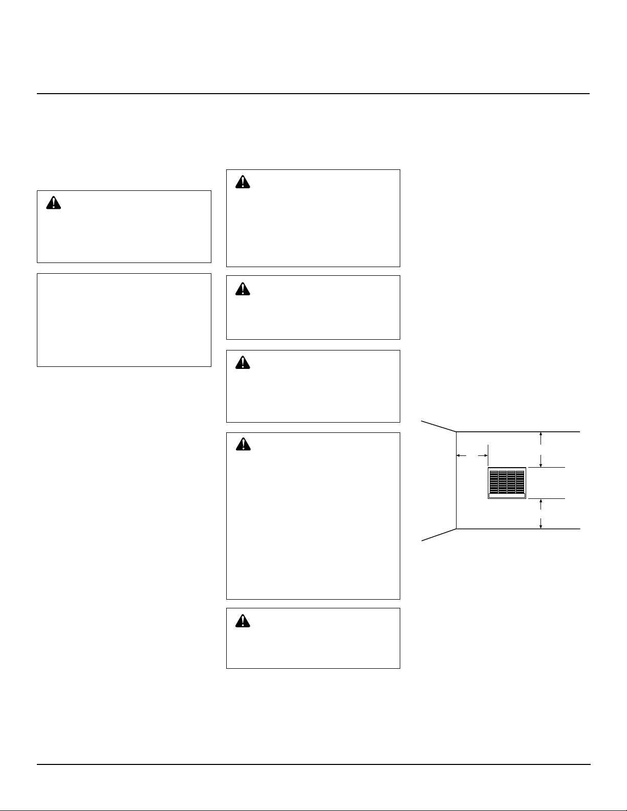
WARNING: Maintain the minimum clearances shown in Figure
1. If you can, provide greater clearances from floor, ceiling, and
joining wall.
WARNING: Due to high temperatures, never install the furnace:
• in an inside wall
• in a recreation vehicle
• in a window recessed in a thick
wall (creating an alcove)
• in an alcove
• behind a door or where an open
door would block normal air flow
• as a fireplace insert
• in high traffic areas
• near furniture or draperies
• in windy or drafty areas
CAUTION: If you install the
furnace in a home garage, locate
furnace where moving vehicle will
not hit it.
For convenience and efficiency, install furnace:
• where there is easy access for operation,
inspection, and service
• in a central location, near an electrical
outlet
• where there is adequate clearance around
vents outside
Before installing furnace, inspect the wall,
floor, and outside areas. Make sure there are
no pipes, wiring, or anything else that would
interfere with furnace installation. If you are
installing thermostat in a wall, make sure
there are no pipes or wiring in the hollow
wall above the furnace. The thermostat wires
will pass through this wall from the attic.
Minimum Clearances
Provide the following minimum clearances
from furnace front cover to combustibles
(as viewed from the front of furnace, see
Figure 1):
Below Front Cover: 6 inches
Above Front Cover: 12 inches
Adjoining Wall: 12 inches
Front: 8 feet
Figure 1 - Mounting Clearances as Viewed
from Front of Furnace
The clearance between the cabinet and the
wall it passes through is 0 inches.
Provide the following minimum clearances
from furnace cabinet (portion of cabinet
extending into outside air, as viewed from
the rear of furnace) to obstructions:
Cabinet Back: 36 inches
Cabinet Sides: 6 inches
Cabinet Bottom: Must be high enough
off the ground to prevent snow, water,
leaves, or any other objects from blocking vents.
4
201835
OWNER’S MANUAL
INSTALLATION
(Continued)
CREATING WALL OPENING
AND MOUNTING FURNACE
Remove furnace front cover. Remove the
two screws at the lower edges of front cover.
Lift front cover away.
Installing in Normal Frame Wall
The 25,000 BTU/Hr model is designed to fit
between two wall studs set at 16 inch on
center. The 40,000 BTU/Hr model will not
fit between wall studs. Follow the steps
below to install.
1. Turn off electrical circuits that pass
through mounting wall. Make sure
there are no pipes or electrical wires in
area you intend to cut.
2. Use stud locator or small finishing nail
to find wall studs. When you locate
studs, drive a small finishing nail into
each stud. This provides a visual reference for stud locations.
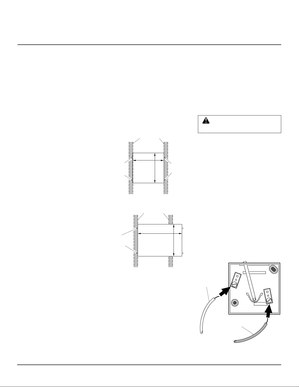
3. 25,000 BTU/Hr Model: Cut an opening in wall between the two studs. Make
opening 141/4" wide by 135/8" high
(see Figure 2).
must install furnace horizontally. Do
not install furnace vertically.
40,000 BTU/Hr Model: Cut a 20
wide by 14 3/8" high opening in wall (see
Figure 2). Start your cut right next to
stud you are going to anchor cabinet to.
Cut across wall and through the next
stud. Stop cut at proper width.
IMPORTANT:
horizontally . Do not install furnace vertically .
4. 25,000 BTU/Hr Model: Mark screw
locations on wall (see Figure 2). Make
sure screws will anchor into studs.
Make sure screw locations match screw
holes on cabinet flange.
40,000 BTU/Hr Model: Mark screw
locations on wall (see Figure 2). Make
sure screws on one side will anchor into
studs. Screws on other side will only
anchor in wall material. Make sure
screw locations match screw holes on
IMPORTANT:
Yo u
5
/16"
Y ou must install furnace
cabinet flange.
5. 25,000 BTU/Hr Model: Use a propersized drill bit. Drill holes through wall
and into studs at marked locations.
40,000 BTU/Hr Model: Use a proper-
sized drill bit. On wall stud side of
opening, drill holes through wall and
into studs at marked locations. On other
side, drill holes through wall material.
6. Insert furnace into opening. Do this
from inside the room. Secure furnace
to wall with four large screws provided.
7. On outside of wall, caulk opening between the cabinet and the rough edges
of opening.
Approx.
Screw
Locations
Wall Studs
1
/4"
14
Wall
Opening
13
5
/8"
Approx.
Screw
Locations
25,000 BTU/Hr Model
Wall Studs
Approx.
Screw
Locations
20 5/16"
Wall Opening
14
3
/8"
40,000 BTU/Hr Model
Figure 2 - Wall Openings and Screw
Locations
Installing in Masonry Wall
You can mount both models in a masonry
wall. Follow the steps below to install.
1. Cut opening in wall. Make opening 14 1/4"
wide by 13 5/8" high for 25,000 BTU/Hr
models. Make opening 20 5/16" wide by
14 3/8" high for 40,000 BTU/Hr models.
IMPORTANT:
furnace horizontally . Do not install furnace vertically.
You must install
2. Secure furnace to wall with toggle bolts
or hook bolts set in mortar.
3. Insert furnace into opening. Do this
from inside the room. Secure furnace
to wall with toggle bolts or hook bolts.
4. On outside of wall, caulk opening between the cabinet and the rough edges
of opening. You can also use mortar to
seal opening.
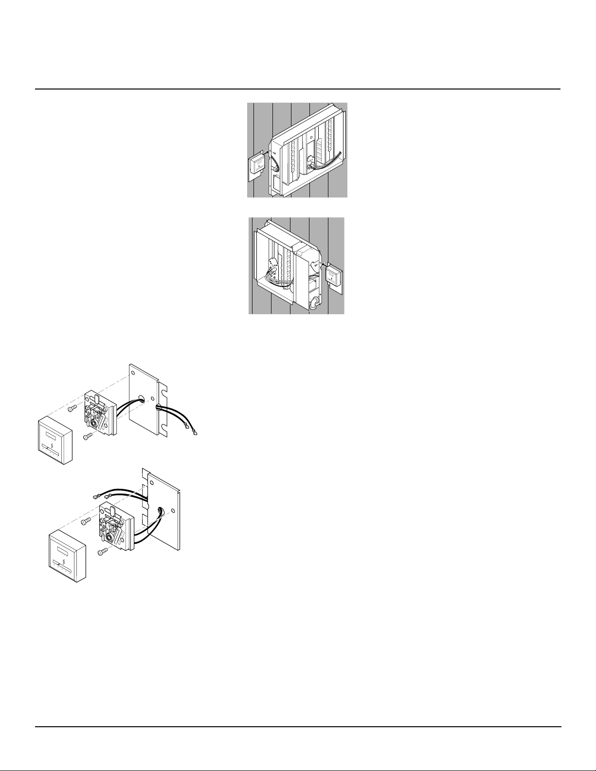
INSTALLING THERMOSTAT
WARNING: Unplug furnace
before installing thermostat.
Mount the thermostat directly on the furnace or on a wall in another part of the room.
If you have solid or masonry walls, mount
the thermostat on the furnace.
Mounting Thermostat to Furnace
1. Unplug furnace.
2. Locate red and white thermostat wires
coming out of side of furnace. These
wires are labeled “Thermostat.”
3. Cut thermostat wires to desired length.
4. Route thermostat wires through slot/
hole in side of thermostat mounting
plate. Then route wires through 5/8"
diameter hole in center of plate (see
Figure 4, page 6).
5. Connect thermostat wires to the two
terminal screws on back of thermostat
(see Figure 3). Connect red wire to “R”
terminal. Connect white wire to “W”
terminal.
White Wire
W
R
Red Wire
Figure 3 - Connecting Thermostat Wires
to Thermostat
Continued
201835
5
®
DYNAVENT
DIRECT-VENT NATURAL GAS HEATER
INSTALLATION
(Continued)
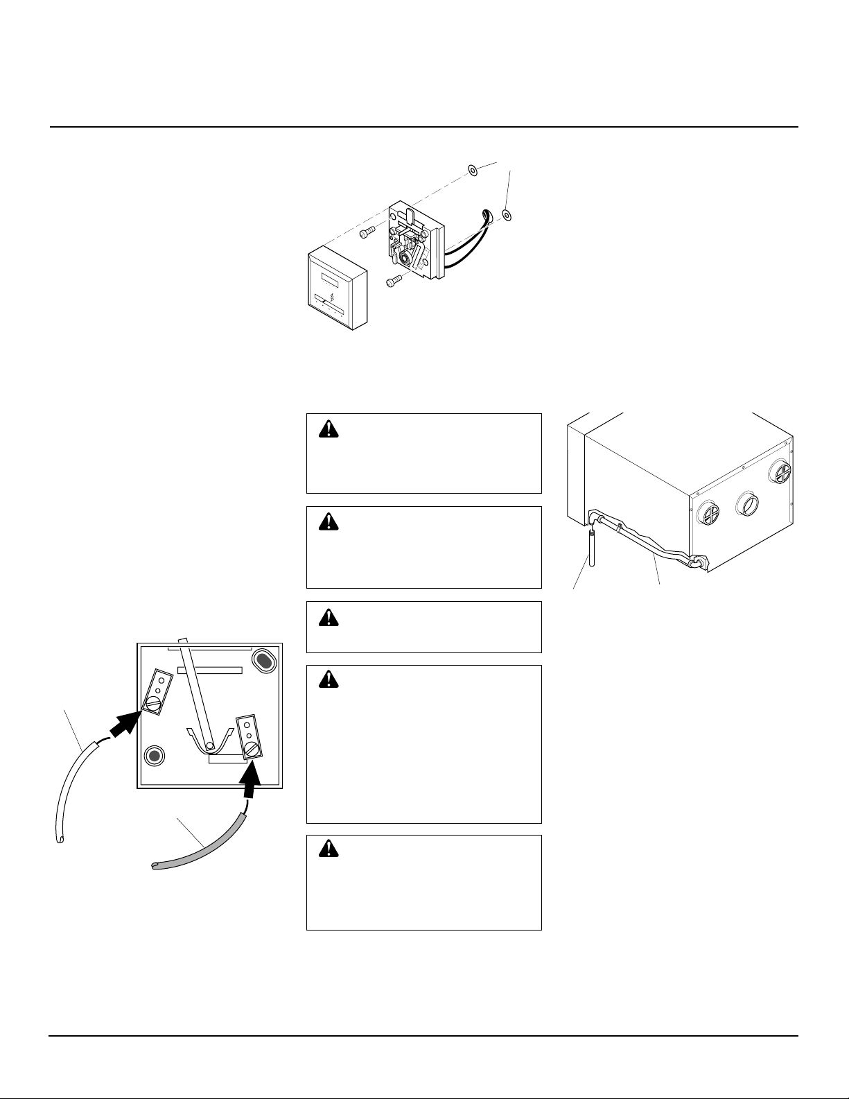
6. Attach thermostat to thermostat mounting plate with screws provided (see Figure 4).
IMPORTANT:
plate position in Figure 4. Correctly
position mounting plate for your model
furnace.
7. Insert thermostat mounting plate between wall and cabinet flange. Line up
top notch on mounting plate with top
screw on flange (see Figure 5).
IMPORTANT:
BTU/Hr model mounts on right side of
furnace (see Figure 5). Thermostat for
40,000 BTU/Hr model mounts on left
side of furnace (see Figure 5).
8. Insert screw in cabinet flange and thermostat mounting plate and tighten firmly .
IMPORT ANT :
wires do not touch combustion chamber.
.2
.3
.4
OFF
.5
.7
50 60 70 80 90
SOLID STATE IGNITION
50 60 70 80 90
50 60 70 80 90
SOLID STATE IGNITION
50 60 70 80 90
Figure 4 - Attaching Thermostat to
Thermostat Mounting Plate
1.0
40,000 BTU/Hr Models
OFF
25,000 BTU/Hr Models
Note mounting
Thermostat for 25,000
Make sure thermostat
.2
.3
.4
.5
.7
1.0
00
0
0 00
00
00
00000000000 00000000
00 00 00 00 00
40,000 BTU/Hr Models
50 60 70 80 90
S
O
L
ID
S
T
A
T
E
IG
N
IT
IO
50 60 70 80 90
N
25,000 BTU/Hr Models
Figure 5 - Inserting Thermostat Mounting
Plate Between Wall and Cabinet Flange
Locating Thermostat on Wall
1. Locate thermostat 4 1/2 to 5 feet above
the floor on an inside wall away from
any heat sources. The thermostat needs
to sense average room temperature.
Avoid the following:
HOT SPOTS
Concealed pipes or ducts
Fireplaces
Registers
TV sets and radios
Lamps or direct sunlight
Kitchen
COLD SPOTS
Concealed pipes or ducts
Stairwells (drafts) or doors (drafts)
Unheated rooms on other side of wall
DEAD SPOTS
Behind doors
Corners and alcoves
2. Before installing thermostat, inspect the
wall, floor, and attic areas. Make sure
there are no pipes, wiring, or anything
else that would interfere with installing thermostat. Do not mount thermostat to stud. If there are any obstructions, choose a new location.
3. Provide two 18-gauge insulated stranded
wires for the thermostat wire. Also provide two wire nuts, and two wall anchors.
There is a red and a white thermostat wire
coming from the furnace. The extra thermostat wires you furnish attach to these
wires. Make sure you furnish a red and a
white wire. This will insure correct
hookup. Purchase enough thermostat wire
to go from the furnace to the thermostat
location. Do not cut and splice this wire.
The thermostat wire must be unbroken.
Routing Thermostat Cable
All wiring must meet local codes. The following instructions cover routing the wire
through the attic. You can run wiring from
a basement or crawl space.
1. Unplug furnace.
2. Before drilling hole in wall, drive a small
finishing nail through ceiling directly
above thermostat location. Pull nail out
and push a small stiff wire through hole.
This helps you locate thermostat mounting location when in attic.
3. In attic, locate stiff wire. Drill 1/2" hole
in center of ceiling wall plate next to
stiff wire. Remove wire.
4. Probe through drilled hole in wall plate
with a stiff wire to make sure there are
no pipes, wiring, or anything else
blocking the way for thermostat wires.
If you find blockage, choose new location for thermostat.
5. Drill a 1/2" hole through the wall at
thermostat mounting location.
6. From attic, feed thermostat wires
through hole in ceiling plate until wires
reach thermostat location.
7. Make a small hook with a piece of stiff
wire. Run wire hook through 1/2" hole
in wall. Hook thermostat wires. Pull
wires through hole in wall. Make sure
6" of wires stick out.
8. Drive a small finishing nail in ceiling
above furnace.
25,000 BTU/Hr Model - Drive nail
above right side of furnace.
40,000 BTU/Hr Model - Drive nail
above left side of furnace.
Pull nail out and push a small stiff wire
through hole. This helps you locate wire
routing location when in attic.
9. Repeat steps 3 and 4 above.
6
201835
OWNER’S MANUAL
INSTALLATION
(Continued)
10. Feed thermostat wires from attic to
furnace through 1/2" hole in ceiling
wall plate.
11. Connect thermostat wires from attic to
thermostat wires on furnace. Connect
red wires together, then connect white
wires together. Use wire nuts to make
connections.
thermostat wires do not touch combustion chamber.
Mounting the Thermostat to Wall
1. Connect thermostat wires to the two
terminal screws on back of thermostat
(see Figure 6). Connect red wire to “R”
terminal. Connect white wire to “W”
terminal.
2. Push any excess wire back through hole
in wall and plug hole with insulation
to prevent drafts. Drafts affect the thermostat operation.
3. Use thermostat base to mark mounting
screw locations.
4. Drill proper-sized holes for wall anchors.
5. Attach thermostat to wall using screws
provided (see Figure 7).
IMPORTANT:
Make sure
Wall
Anchors
.2
.3
.4
OFF
.5
.7
1.0
50 60 70 80 90
SOLID STATE IGNITION
50 60 70 80 90
Figure 7 - Mounting Thermostat to Wall
CONNECTING TO GAS
SUPPLY
WARNING: A qualified service person must connect furnace to gas supply. Follow all
local codes.
WARNING: Never connect
furnace to private (non-utility) gas
wells. This gas is commonly
known as wellhead gas.
WARNING: Unplug furnace
before connecting to gas supply.
All piping must comply with local codes
and ordinances or with the National Fuel
Gas Code (ANS Z223.1 NFPA No. 54),
whichever applies.
You can connect furnace to gas supply at
front of furnace (inside) or at rear of furnace
(outside).
Connecting Furnace to Gas
Supply at Front of Furnace
1. Locate gas inlet pipe on lower, right
front of furnace (see Figure 8).
2. Connect 3/8" NPT pipe or nipple to gas
inlet pipe (see Figure 8). See Provid-
ing Gas Piping to Furnace, pages 9 and
10, for correct gas pipe installation.
3/8" NPT
Pipe or
Nipple
Figure 8 - Connecting Gas from Inside of
Room
Gas Inlet Pipe
White Wire
W
R
Red Wire
Figure 6 - Connecting Thermostat Wires
to Thermostat
201835
CAUTION: Use only new,
black iron or steel pipe. Copper
tubing may be acceptable in certain areas. Check local codes.
Use pipe large enough in diameter to allow proper gas volume
to furnace. If pipe is too small,
undue loss of pressure will occur. Refer to chart on page 9.
CAUTION: Lightly apply pipe
joint sealant to male threads before connecting. Use pipe joint
sealant that is resistant to liquid
petroleum (LP) gas.
Continued
7
®
DYNAVENT
DIRECT-VENT NATURAL GAS HEATER
INSTALLATION
(Continued)
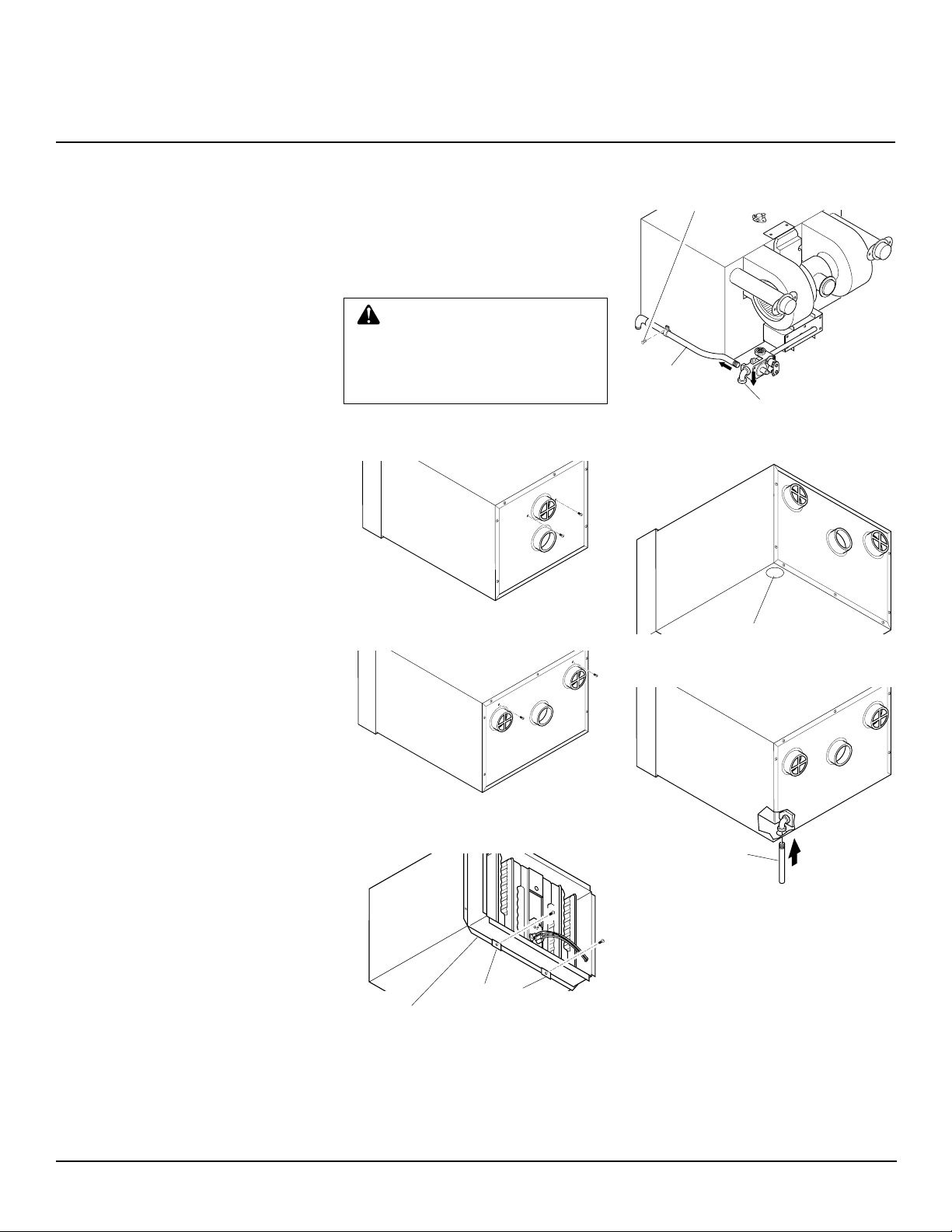
Connecting Furnace to Gas
Supply at Rear of Furnace
1. Remove the two screws in back of furnace cabinet located by the exhaust
vent(s) (see Figures 9 and 10).
2. Remove two screws on front lower
flange that attach furnace flange to furnace cabinet flange (see Figure 11).
Note:
40,000 BTU/Hr model has a bottom shield (see parts list, page 22, for
location). Removing two screws will
detach bottom shield.
3. Slide furnace out of furnace cabinet.
4. Locate gas inlet pipe on lower, right
front of furnace.
5. 40,000 BTU/Hr Model Only: Remove
screw holding gas inlet pipe clamp to
furnace.
6. Disconnect gas inlet pipe from 3/8"
manifold elbow. Turn gas inlet pipe
counterclockwise to disconnect (see
Figure 12).
7. Rotate the 3/8" manifold elbow 90° so
the opening is pointing downward (see
Figure 12).
8. Locate knockout plug in furnace cabinet. Knockout plug is in lower left rear
of furnace cabinet (as viewed from rear,
see Figure 13). Remove knockout plug.
9. Slide furnace back into furnace cabinet. Make sure exhaust tube gaskets are
in place. Make sure exhaust and intake
vent tubes extend into vent caps on
back of cabinet. Replace two screws by
exhaust vent(s) removed in step 1.
10. 25,000 BTU/Hr Model: Replace two
screws removed in step 2. Attach furnace flange and furnace cabinet lower
flange together.
40,000 BTU/Hr Model: Place bottom
shield back in place. Replace two
screws removed in step 2. Attach bottom shield, furnace flange, and furnace
cabinet lower flange together.
11. Run 3/8" pipe or nipple through knockout hole. Connect 3/8" pipe or nipple
to manifold elbow (see Figure 14). See
Providing Gas Piping to Furnace,
pages 9 and 10 for correct gas pipe installation.
12. Check connections for gas leak.
WARNING: Never use an open
flame to check for a leak. Apply a
mixture of liquid soap and water
to all joints. Bubbles forming show
a leak. Correct all leaks at once.
13. Caulk around pipe or nipple. This prevents cold air entering knockout hole.
Figure 9 - Locations of Screws in Back of
Furnace Cabinet (25,000 BTU/Hr Model)
Figure 10 - Locations of Screws in Back
of Furnace Cabinet (40,000 BTU/Hr Model)
Furnace
Furnace
Cabinet
Flange
Figure 11 - Removing Screws on Lower
Flange (40,000 BTU/Hr Model Shown)
Flange
Remove Screw,
40,000 BTU/Hr
Model Only
Gas Inlet
Pipe
Manifold Elbow
Figure 12 - Disconnecting Gas Inlet Pipe
(40,000 BTU/Hr Model Shown)
Knockout Plug
Figure 13 - Location of Knockout Plug
3/8" NPT
Figure 14 - Inserting Pipe through
Knockout Hole
8
201835
OWNER’S MANUAL
INSTALLATION
(Continued)
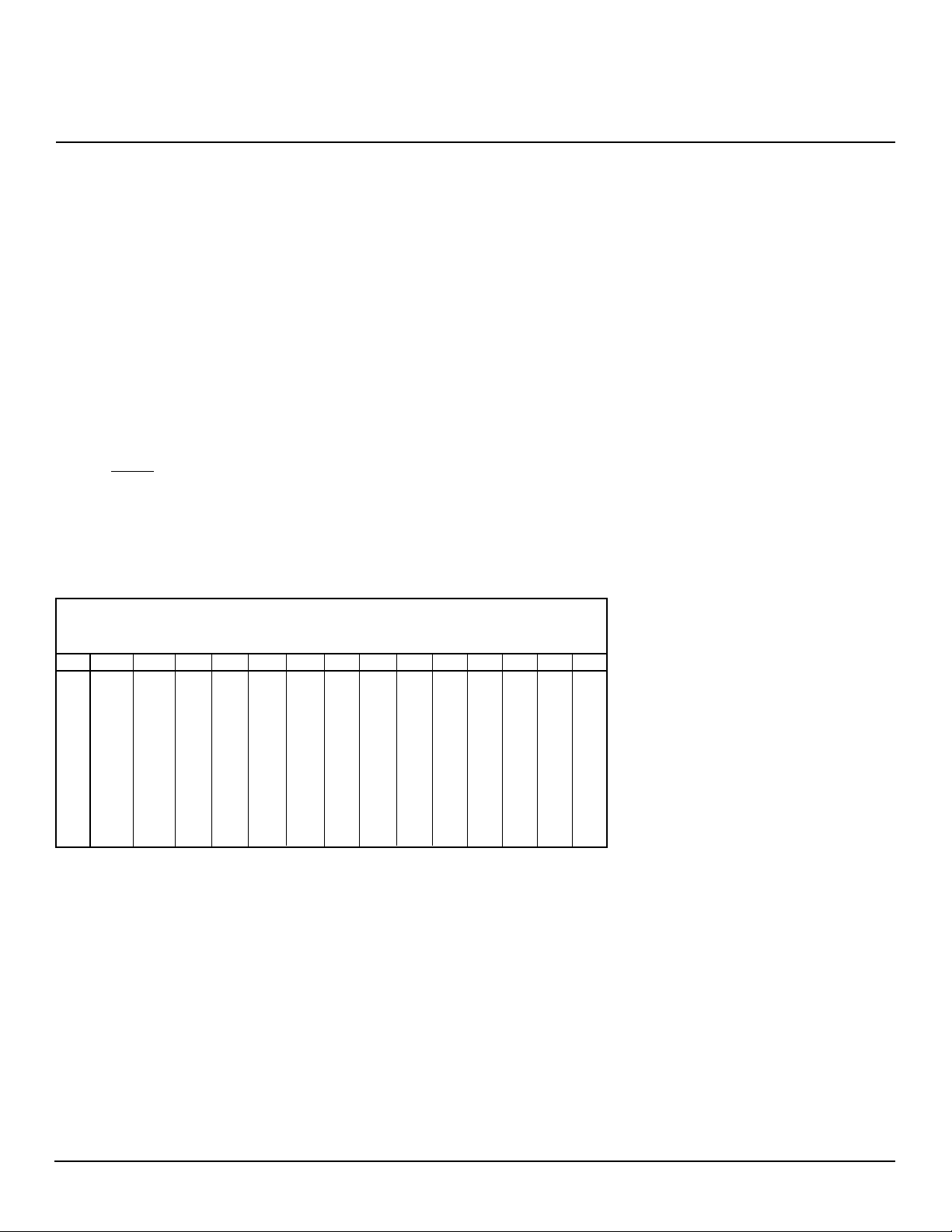
Providing Gas Piping to Furnace
You must provide gas piping from gas source to furnace. The gas piping must be in a vertical
position where it connects to the furnace. This prevents interference with front cover
installation.
Consult your local gas company for proper routing of the gas lines.
Pipe size is determined by the length of pipe from the gas source to the furnace and the total
BTU load on the gas source.
Add the total BTUs required for all appliances connected to the gas source including this furnace.
Divide this number by 1030. This will give you the approximate cubic feet per hour needed.
Example:
40,000 BTU/Hr
+ 15,000 BTU/Hr for other gas appliances
55,000 BTU/Hr total
55,000 ÷ 1030 = 53.4
Locate 53.4 or higher on chart below.
According to the chart below, you should use 50 feet or less of 1/2" pipe, 200 feet
or less of 3/4" pipe, etc...
MINIMUM
IRON PIPE
SIZE LENGTH OF PIPE (FEET)
10 20 30 40 50 60 70 80 90 100 125 150 175 200
3/8" 72 49 40 34 30 27 25 23 22 21 18 17 15 14
1/2" 132 92 73 63 56 50 46 43 40 38 34 31 28 26
3/4" 278 190 152 130 115 105 96 90 84 79 72 64 59 55
1" 520 350 285 245 215 195 180 170 160 150 130 120 110 100
1
/4" 1050 730 590 500 440 400 370 350 320 305 275 250 225 210
1
11/2" 1600 1100 890 760 670 610 560 530 490 460 410 380 350 320
2" 3050 2100 1650 1450 1270 1150 1050 990 930 870 780 710 650 610
21/2" 4800 3300 2700 2300 2000 1850 1700 1600 1500 1400 1250 1130 1050 980
3" 8500 5900 4700 4100 3600 3250 3000 2800 2600 2500 2200 2000 1850 1700
4" 17500 12000 9700 8300 7400 6800 6200 5800 5400 5100 4500 4100 3800 3500
IMPORTANT:
Check gas line pressure at gas meter before connecting furnace to gas line. Gas
line pressure must be no less than 5 inches of water and no greater than 7 inches of water. Gas
pressures and input to the burners must not exceed the rated input and pressure shown on the
rating plate. For natural gas, manifold pressure should be 3.5 inches of water. For elevations
above 2000 feet, reduce rating 4% for each 1000 feet above sea level (U.S.A. only).
201835
Continued
9
 Loading...