


013300xx
Betriebsanleitung
- Original -
Operating manual
- Translation of original -
Steuerung Zuführgeräte /
Controller feeding machines
SZG Controller 6
362625 A
ALLE DOKUMENTATIONEN BEACHTEN !
Vor Beginn der Arbeit diese Betriebsanleitung und die beiliegenden
Sicherheitsvorschriften (Nr. 016000, rosafarbenes Booklet) sorgfältig durchlesen und
die Anweisungen beim Betrieb befolgen. Übergeben Sie diese Betriebsanleitung und die
zugehörigen Sicherheitsvorschriften dem Benutzer.
NOTICE ALL DOCUMENTATIONS !
Before beginning work this operating instruction booklet and the enclosed
safety instructions (no. 016000, pink-colored booklet) have to be read through
carefully. Always follow the instructions during operation. Give this operating
instruction booklet and the appropriate safety instructions to the operator.
013300 - Version 3.01 - Jun-11 Änderungen vorbehalten

SZG CONTROLLER 6 - DEUTSCH
Inhaltsverzeichnis / Contents
1 EINFÜHRUNG............................................................................................................................. 7
2 FUNKTIONSWEISE DER STEUERUNG...................................................................................... 8
3 BEDIENUNG................................................................................................................................ 9
3.1 BESCHREIBUNG DES DISPLAYS.............................................................................................. 9
3.2 BESCHREIBUNG DER TASTATUR............................................................................................. 9
3.3 BESCHREIBUNG DES MENÜS................................................................................................... 9
3.3.1 MENÜ-REIHENFOLGE:..............................................................................................................10
3.3.2 MENÜBAUM...............................................................................................................................11
4 FUNKTIONEN UND EINSTELLUNGEN......................................................................................12
4.1 NACHLADEN..............................................................................................................................12
4.2 HOCHFÖRDERN........................................................................................................................12
4.3 TESTFUNKTIONEN....................................................................................................................12
4.3.1 EIN-/AUSGÄNGE........................................................................................................................12
4.3.2 FÖRDERTOPF...........................................................................................................................12
4.4 WIEDERHERSTELLEN DES AUSLIEFERUNGSZUSTANDES...................................................12
4.5 LASTREGELUNG (DMS)............................................................................................................13
4.6 SANFTANLAUF..........................................................................................................................13
4.7 BETRIEB OHNE DMS.................................................................................................................13
4.8 RFID...........................................................................................................................................14
4.9 EINLAUF- / EINSCHUSSKONTROLLE.......................................................................................14
4.10 FÜLLSTANDSKONTROLLE........................................................................................................15
4.11 BANDBUNKERANSTEUERUNG ................................................................................................15
4.12 BENUTZER ................................................................................................................................16
2

4.13 ZEITEN.......................................................................................................................................16
4.13.1 VORLAUFZEIT...........................................................................................................................16
4.13.2 NACHLAUFZEIT.........................................................................................................................16
4.13.3 VEREINZELUNGSZEIT ..............................................................................................................16
4.13.4 SCHUSSLUFTVERZÖGERUNG.................................................................................................16
4.13.5 SCHUSSLUFTDAUER................................................................................................................16
4.13.6 FÖRDERTOPFNACHLAUFZEIT.................................................................................................17
4.13.7 BLASLUFTVERLÄNGERUNG.....................................................................................................17
4.14 PASSWORT...............................................................................................................................17
SZG CONTROLLER 6 - DEUTSCH
4.15 SPRACHE ..................................................................................................................................17
4.16 DISPLAYANZEIGE.....................................................................................................................17
4.16.1 STANDARD................................................................................................................................17
4.16.2 ZAEHLER...................................................................................................................................18
4.16.3 SCHRAUBZEIT...........................................................................................................................18
4.16.4 KOMBINIERT..............................................................................................................................19
5 OPTIONALES ZUBEHÖR...........................................................................................................19
5.1 EINLAUF- / EINSCHUSSKONTROLLE.......................................................................................19
5.2 FÜLLSTANDSKONTROLLE........................................................................................................19
5.3 BANDBUNKERANSTEUERUNG ................................................................................................19
5.4 RFID...........................................................................................................................................20
5.5 PC-SOFTWARE..........................................................................................................................21
6 KABELBELEGUNG.....................................................................................................................22
6.1 SIGNALDAUER FÜR START 1 – 4 (NUR TYP EP).....................................................................22
6.2 SIGNALDAUER FÜR START TOPF (NUR TYP 0 UND P)..........................................................22
3

6.3 EXTERNE SIGNALERZEUGUNG FÜR TYP 1611 UND 24V-VERSORGUNG DER
(OPTIONALEN) SENSORIK.......................................................................................................................22
6.4 EINGÄNGE.................................................................................................................................23
6.5 STECKERBELEGUNGEN...........................................................................................................24
6.6 AUSGÄNGE................................................................................................................................25
7 FEHLERMELDUNGEN / BETRIEBSZUSTÄNDE.........................................................................26
8 ENGLISH - INTRODUCTION......................................................................................................27
9 CONTROLLER FUNCTION.........................................................................................................28
10 OPERATION...............................................................................................................................29
10.1 DESCRIPTION OF THE DISPLAY..............................................................................................29
SZG CONTROLLER 6 - DEUTSCH
10.2 DESCRIPTION OF THE KEYPAD...............................................................................................29
10.3 DESCRIPTION OF THE MENU...................................................................................................29
10.3.1 MENU SECTIONS APPEAR AS FOLLOWS:...............................................................................30
10.3.2 MENU.........................................................................................................................................31
11 FUNCTIONS AND SETTINGS....................................................................................................32
11.1 RELOAD.....................................................................................................................................32
11.2 FILL RUN....................................................................................................................................32
11.3 TEST FUNCTIONS.....................................................................................................................32
11.3.1 INPUTS/OUTPUTS.....................................................................................................................32
11.3.2 VIBRATORY BOWL....................................................................................................................32
11.4 RESTORE FACTORY SETTINGS...............................................................................................32
11.5 LOAD CONTROL (STRAIN GAUGE)..........................................................................................33
11.6 SOFT START..............................................................................................................................33
11.7 OPERATION WITHOUT STRAIN GAUGE..................................................................................33
4

11.8 RFID...........................................................................................................................................34
11.9 INLET CONTROL / HOSE SCREW SENSOR.............................................................................34
11.10 FILL LEVEL SENSOR.................................................................................................................35
11.11 LINEAR HOPPER CONTROL.....................................................................................................35
11.12 USER..........................................................................................................................................36
11.13 TIMES.........................................................................................................................................36
11.13.1 MIN. DRIVER TIME.....................................................................................................................36
11.13.2 NEW CYCLE DELAY..................................................................................................................36
11.13.3 SEP. FORWARD........................................................................................................................36
SZG CONTROLLER 6 - DEUTSCH
11.13.4 AIR-PUSH DELAY......................................................................................................................36
11.13.5 PART AIR-PUSH........................................................................................................................36
11.13.6 BOWL RUN TIME.......................................................................................................................37
11.13.7 RAIL BLOW-OFF........................................................................................................................37
11.14 PASSWORD...............................................................................................................................37
11.15 LANGUAGE................................................................................................................................37
11.16 DISPLAY.....................................................................................................................................37
11.16.1 STANDARD................................................................................................................................37
11.16.2 COUNTER..................................................................................................................................38
11.16.3 PART ASSEMBLY TIME.............................................................................................................38
11.16.4 COMBINED ................................................................................................................................39
12 OPTIONAL ACCESSORIES........................................................................................................39
12.1 INLET CONTROL / HOSE SCREW SENSOR.............................................................................39
12.2 FILL LEVEL SENSOR.................................................................................................................39
12.3 LINEAR HOPPER CONTROL.....................................................................................................39
5

12.4 RFID...........................................................................................................................................40
12.5 PC-SOFTWARE..........................................................................................................................41
13 CABLE LAYOUT.........................................................................................................................42
13.1 SIGNAL DURATION FOR START 1 – 4 (ONLY TYPE EP)..........................................................42
13.2 SIGNAL DURATION FOR START BOWL (ONLY TYPE EP).......................................................42
13.3 PROVIDING OF EXTERNAL PING FOR TYPE 1611 AND 24V-INPUT OF THE (OPTIONAL)
SENSORS..................................................................................................................................................42
13.4 INPUTS ......................................................................................................................................43
13.5 PLUG CONFIGURATION............................................................................................................44
13.6 OUTPUTS...................................................................................................................................45
SZG CONTROLLER 6 - DEUTSCH
14 ERROR MESSAGES / OPERATIONAL STATUS........................................................................46
15 NOTIZEN / NOTES.....................................................................................................................47
SERVICE STATIONS AND AUTHORISED PARTNERS.............................................................................48
HINWEIS:
Die Steuerung wird nur im Zusammenhang mit einem Zuführgerät der DEPRAG SCHULZ
GMBH u. CO. vertrieben. Bitte beachten Sie auch weiterführende Nutzungshinweise in der
Technischen Dokumentation des zugehörigen Zuführgerätes.
NOTE:
The controller is only to be used in connection with a feeder from DEPRAG SCHULZ GMBH &
CO. Please pay attention to the further instructions for use in the technical documentation of
the associated feeder.
6

SZG CONTROLLER 6 - DEUTSCH
1 Einführung
Die elektronische Ablaufsteuerung übernimmt alle für den Betrieb des Zuführgerätes Serie 6 nötigen
Steuerungsaufgaben. Sie ist so konzipiert, dass eine optimale Einstellung des Programmablaufes
komfortabel über das integrierte Menü für jeden Anwendungsfall möglich ist.
Bei der Optimierung des Schraubzyklus sind im Wesentlichen folgende Größen ausschlaggebend:
• Schraubzeit in Abhängigkeit vom Schraubteil
• Länge der Schraube
• Länge des Zuführschlauches
• Förderverhalten der Schrauben im Topf
• Arbeitsgeschwindigkeit des Bedieners / der Bedienerin.
Die Förderleistung des Topfes wird mittels eines DMS-Sensors und einer Phasenanschnittsteuerung
konstant gehalten. Damit werden unterschiedliche Füllstände, Temperaturschwankungen etc. automatisch
kompensiert. Ein Sanftanlauf des Fördertopfes ist optional zuschaltbar.
Es können unterschiedliche Zeiten für bis zu 10 Bediener eingestellt werden. Die Umstellung auf einen
anderen Bediener erfolgt über das Menü oder optional über RFID.
Die Steuerung verfügt über einen Weitspannungseingang von 100-260V / 50/60Hz. Eine manuelle
Umschaltung zwischen 230V und 115V ist nicht notwendig.
Das Netzteil ist dauerkurzschlussfest.
Das Ein- bzw. Ausschalten der Steuerung erfolgt über den Kippschalter an der Frontplatte. Eine Leuchtdiode
zeigt den Schaltzustand an.
Bild 1: Zuführgerät Serie 6 mit Option RFID
Die Steuerung für das Zuführgerät Serie 6 ist für folgende Ausführungen erhältlich:
• 1611, 1622: Handgerät mit Einfachwendel und Doppelwendel
• 0611-EP, 0622-EP: Stationäres Gerät mit Einfachwendel und Doppelwendel
• 0611-2-EP, 0611-3-EP, 0611-4-EP:
• Stationäres Gerät mit Einfachwendel und Zwei- Drei- bzw.
• Vierfachverteiler
• 06xx-0: Geräte der Ausführung 0
• 06xx-P: Geräte der Ausführung P
• sowie Linearförderer
7

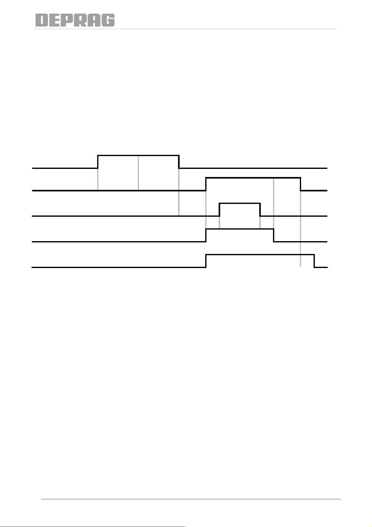
2 Funktionsweise der Steuerung
Der Gesamtzyklus des Zuführgerätes setzt sich aus folgenden Phasen zusammen:
SZG CONTROLLER 6 - DEUTSCH
• Vorlaufzeit t
• Nachlaufzeit tn
v
• Schussluftverzögerung t
z
• Schussluftdauer ts
• Vereinzelungszeit te
• Fördertopfnachlaufzeit t
f
• Blasluftverlängerung tb
Start
Topf
Schussluft
Vereinzelung
t
v
t
t
n
t
t
z
s
t
e
f
Blasluft tb
Die Vorlaufzeit ist die Dauer, die der Schrauber mindestens gelaufen sein muss, damit die Steuerung den
Einschusszyklus aktiviert.
Die Nachlaufzeit definiert die Dauer vom Moment des Abschaltens des Schraubers bis zum Beginn des
Vereinzelungs- und Zuführvorgangs der nächsten Schraube.
Die Schussluftverzögerung ist die Zeitdauer von der Aktivierung des Ventils für Vereinzelung vorwärts
(Vereinzelung fährt in Einschussposition) bis zum Aktivieren des Ventils für die Schussluft
.
Die Schussluftdauer ist die Zeitdauer, welche das Ventil für die Schussluft geöffnet ist.
Die Vereinzelungszeit ist die Zeitdauer für welche die Vereinzelung in Einschuss-Position verweilt.
Die Fördertopfnachlaufzeit ist die Zeitdauer, welche der Schwingförderer nach Abschluss der
Vereinzelungszeit noch angesteuert bleibt.
Die Blasluftverlängerung ist die Zeitdauer, welche das Ventil für die Blasluftabweiser am Fördertopf nach
dem Abschalten des Schwingförderantriebes noch geöffnet bleibt.
8

SZG CONTROLLER 6 - DEUTSCH
3 Bedienung
3.1 Beschreibung des Displays
Im Auslieferungszustand zeigt das Display der Zuführgeräte-Steuerung den Standardbildschirm. Eine
andere Anzeige kann über das Menü gewählt werden.
Bild 2: Display mit Standardanzeige
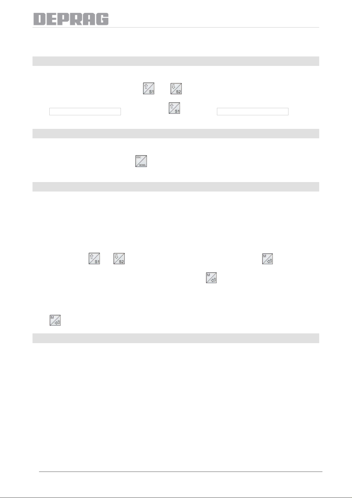
3.2 Beschreibung der Tastatur
TASTE BEDEUTUNG
Aufruf des Menüs
Auswahl von Menüpunkten
Verlassen eines Menüpunktes mit Speichern
Anforderung Schraube 1
Anzeige des vorherigen Menüpunktes
Anforderung Schraube 2 (nur bei Doppelwendelgeräten)
Anzeige des nächsten Menüpunktes
Verlassen eines Menüpunktes ohne Speichern
Starten des Fördertopfes (wenn das Menü nicht aktiv ist)
3.3 Beschreibung des Menüs
Beim Drücken auf die Taste
werden. Solange das Passwort den Defaultwert hat (Default ist 0000), ist keine Passworteingabe nötig.
Mit
Im Untermenü kann mit den Tasten
übernommen und wieder das (übergeordnete) Menü angezeigt. Wird innerhalb des Menüs die Taste
gedrückt, gelangt man zum vorhergehenden Menüpunkt.
und kann innerhalb des Menüs geblättert werden. Mit wird in das Untermenü gewechselt.
wird das Menü angezeigt. Es muss das Benutzerpasswort eingegeben
und ein Wert eingestellt werden. Mit wird dieser Wert
HINWEIS:
Das Zuführgerät kann erst wieder Schrauben zuführen, wenn das Menü beendet wurde.
Durch Betätigen der Tasten
oder können Sie die einzelnen Punkte im Menü durchblättern.
9

3.3.1 Menü-Reihenfolge:
BENUTZERWECHSEL: Auswahl eines Bedieners
ZEITEN: Einstellungen der Zeiten für den aktiven Benutzer
VORLAUFZEIT: die Vorlaufzeit
NACHLAUFZEIT: die Nachlaufzeit
SCHUSSLUFTDAUER: die Schussluftdauer
VEREINZELZEIT: die Vereinzelungszeit
TOPFNACHLAUFZEIT: die Nachlaufzeit des Schwingförderers
SL-VERZOEGERUNG: die Schussluftverzögerung
BL-VERLAENGERUNG: die Blasluftverlängerung
LASTREGELUNG: die Lastregelung für den Schwingförderer in 50 Teilstufen
SANFTANLAUF: der Sanftanlauf kann ein- oder ausgeschaltet werden
SPRACHE WAEHLEN: es kann zwischen mehreren Sprachen gewählt werden
LIEFERZUSTAND: Wiederherstellung des Auslieferungszustandes
RFID: Zuordnung von RFID-Tags zu Benutzern
PASSWORT AENDERN: Einstellen eines Passwortes, um den Zugriff auf das
Menü für Unbefugte zu verhindern
ANZEIGE: Auswahl eines Anzeigebildschirms
STANDARD: Anzeige der Benutzernummer
SZG CONTROLLER 6 - DEUTSCH
ZAEHLER: Anzeige der Anzahl der Schrauben pro Zuführung seit
Einschalten der Zuführgeräte-Steuerung (bei Erreichen
von 65565 fängt der Zähler wieder bei 1 an)
SCHRAUBZEIT: Zeit, die eine Verschraubung gedauert hat
KOMBINIERT: Anzahl der Schrauben und Verschraubungszeit
werden angezeigt
TESTFUNKTIONEN:
EINGAENGE: Test der Eingänge auf Funktionsfähigkeit
AUSGAENGE: Test der Ausgänge auf Funktionsfähigkeit
TOPF: Test des Fördertopfes auf Funktionsfähigkeit
BETRIEB OHNE DMS:
AKTIVIEREN: Aktivierung des Betriebs ohne DMS
EINSTELLUNG: Einstellung der optimalen Vibration des
Schwingförderers in 50 Teilstufen
SYSTEMINFO: Anzeige von Systeminformationen
10

3.3.2 Menübaum
---------> BENUTZERWECHSEL
---------> ZEITEN
---------> VORLAUFZEIT
---------> NACHLAUFZEIT
---------> VEREINZEL-ZEIT
---------> SL-VERZOEGERUNG
---------> SCHUSSLUFTDAUER
---------> TOPFNACHLAUFZEIT
---------> BL-VERLAENGERUNG
---------> LASTREGELUNG
---------> SANFTANLAUF
---------> SPRACHE WAEHLEN
---------> LIEFERZUSTAND
SZG CONTROLLER 6 - DEUTSCH
---------> RFID
---------> PASSWORT AENDERN
---------> ANZEIGE
---------> TESTFUNKTIONEN
---------> EINGAENGE
---------> AUSGAENGE
---------> TOPF
---------> BETRIEB OHNE DMS
---------> AKTIVIEREN
---------> EINSTELLUNG
---------> SYSTEMINFO
---------> VERSION
---------> SERIEN-NR.
HINWEIS:
Nicht alle Optionen sind für alle Gerätetypen verfügbar !
11
SZG CONTROLLER 6 - DEUTSCH
4 Funktionen und Einstellungen
4.1 Nachladen
Wenn sich keine Schraube in der Kugel- bzw. Schnabelhülse befindet, kann eine Schraube manuell
nachgeladen werden.
Wird am Standardbildschirm die Taste
bzw. 1622 über die entsprechende Vereinzelung ein Nachladevorgang ausgelöst.
Beim Zuführgerät vom Typ 1611 ist nur die Taste
Tasten belegt, wobei jede Taste für eine Vereinzelungsseite zuständig ist.
bzw. gedrückt, so wird beim Zuführgerät vom Typ 1611
belegt, beim Zuführgerät vom Typ 1622 sind beide
4.2 Hochfördern
Nachdem der Fördertopf leer war und neue Schrauben aufgefüllt wurden, können diese Schrauben manuell
nach oben gefördert werden.
Wird am Standardbildschirm die Taste
sich nach 5 Sekunden automatisch aus.
gedrückt, so wird der Fördertopf aktiviert. Der Fördertopf schaltet
4.3 Testfunktionen
Im Menü TESTFUNKTIONEN können sowohl die Ein- und Ausgänge der Steuerung, sowie die Ansteuerung
des Fördertopfes auf Funktionsfähigkeit überprüft werden.
4.3.1 Ein-/Ausgänge
Im Untermenü EINGAENGE sind die Eingänge von 1 bis 6 aufgelistet (siehe Anhang Ein-/Ausgänge). Wird
ein Eingang auf 1 gesetzt, wird im Display für diesen Eingang eine 1 angezeigt.
Im Untermenü AUSGAENGE sind die Ausgänge von 1 bis 8 aufgelistet (siehe Anhang Ein-/Ausgänge). Wird
über die Pfeiltasten (
auf 1 gesetzt, dann wird der entsprechende Ausgang aktiviert. Wird beispielsweise der Ausgang 1 gesetzt,
und ) ein Ausgang angewählt und anschließend mit der - Taste der Wert
schaltet sich die Blasluft an. Durch nochmaliges Drücken auf die
zurückgesetzt.
-Taste wird der Ausgang wieder auf 0
4.3.2 Fördertopf
Im Untermenü TOPF kann der Fördertopf gestartet und wieder angehalten werden. Durch Drücken der
Taste
wird der Fördertopf gestartet, durch nochmaliges Drücken wieder angehalten.
4.4 Wiederherstellen des Auslieferungszustandes
Im Menüpunkt LIEFERZUSTAND kann der Auslieferungszustand ab Werk DEPRAG wiederhergestellt
werden.
Dabei werden folgende Einstellungen mit den werkseitig voreingestellten Werten ersetzt:
• alle eingestellten benutzerabhängigen Zeiten
• Passwort
• Displaydarstellung
• Sanftanlauf
• Betrieb ohne DMS
12

HINWEIS:
Im Auslieferungszustand ist kein Passwortschutz für das Menü gegeben. Wenn Sie ein
Passwort eingerichtet haben und den Auslieferungszustand wiederherstellen, müssen Sie das
Passwort wieder neu setzen.
SZG CONTROLLER 6 - DEUTSCH
4.5 Lastregelung (DMS)
Bild 3: Anwendungsbeispiel - DMS-Streifen am Fördertopf
Das Zuführgerät Serie 6 verwendet einen Dehnmessstreifen (DMS), um die aktuelle Vibration zu messen
und berechnet daraus die notwendige Ansteuerung des Fördertopfes. Die resultierende Vibration ist
unabhängig vom Füllstand des Fördertopfes.
Im Menüpunkt LASTREGELUNG kann die Intensität der Vibration des Schwingförderers eingestellt werden.
Durch Drücken der Taste
Lastregelung ist in 50 Stufen möglich.
wird die Vibration stärker, durch Drücken der Taste geringer. Die
4.6 Sanftanlauf
Die Steuerung für das Zuführgerät Serie 6 verfügt über einen integrierten Sanftanlauf.
Im Menüpunkt SANFTANLAUF kann der Sanftanlauf ein- oder ausgeschaltet werden.
4.7 Betrieb ohne DMS
Das Zuführgerät Serie 6 wird im Normalfall mit DMS betrieben. Für den Fall, dass die Ansteuerung des
Fördertopfes über den DMS nicht mehr funktionsfähig ist, kann die Steuerung auf Betrieb ohne DMS
(Notbetrieb) umgestellt werden.
Der Linearförderer arbeitet im Standard ohne DMS. Die Einstellung erfolgt immer im Menü BETRIEB OHNE
DMS → EINSTELLUNG.
Im Menüpunkt BETRIEB OHNE DMS wird zuerst im Unterpunkt AKTIVIEREN auf „ja“ umgestellt.
Anschließend wird im Unterpunkt EINSTELLUNG die Lastregelung für den Fördertopf eingestellt. Die
Lastregelung ist in 50 Stufen möglich.
HINWEIS:
Im Betrieb ohne DMS vibriert der Fördertopf je nach Füllungsgrad schwächer oder stärker.
13

SZG CONTROLLER 6 - DEUTSCH
4.8 RFID
Bild 4: Lesegerät mit Verbindungskabel und drei RFID-Tags
Im Menüpunkt RFID können die RFID-Tags (die kodierten Chips) für alle Benutzer angelernt werden. Der
Benutzer wird in Klammern am Ende der Zeile angezeigt. Über die Tasten
gewünschte Benutzernummer ausgewählt werden. Anschließend wird das dazugehörige RFID-Tag am
Lesegerät eingelesen. Im Display erscheint die ID des Tags. Nach Drücken auf die Taste
der ausgewählten Benutzernummer gespeichert.
Nach dem Anlernen der IDs kann der Benutzer einfach gewechselt werden, indem das RFID-Tag kurz an
das Lesegerät gehalten wird.
Damit ist es möglich, die Zeiten für bis zu 10 Benutzer zu wechseln und das Zuführgerät individuell für
verschiedene Benutzer einzurichten.
und kann die
wird die ID zu
4.9 Einlauf- / Einschusskontrolle
Bild 5: Verschiedene Varianten von Einlaufkontrollen bzw. Einschusskontrolle am Schlauch
Handgeräte können mit zusätzlichen Kontrollen für das Abfragen von Zuführteilen ausgestattet werden. Zur
Auswahl stehen Einlaufkontrolle (in die Vereinzelung) und Einschusskontrolle (am Schlauch kurz vor dem
Mundstück). Bei Doppelwendelgeräten muss für beide Seiten die gleiche Einlauf- bzw. Einschusskontrolle
verwendet werden.
14

Wird die Einlaufkontrolle verwendet, so wird geprüft, ob sich ein Zuführteil in der Vereinzelung befindet. Ist
dies bei Start eines Vereinzelungszyklus, bzw. 60 Sekunden nach der letzten Vereinzelung nicht der Fall, so
wird eine Warnmeldung ausgegeben.
Wird die Einschusskontrolle verwendet, so wird geprüft, ob das Zuführteil am Schrauber ankommt. Ist dies
nicht der Fall, so wird noch zweimal versucht nachzuladen, bevor eine Warnmeldung angezeigt wird.
SZG CONTROLLER 6 - DEUTSCH
4.10 Füllstandskontrolle
Bild 6: Verschiedene Varianten von Füllstandsanzeigen
Mit Hilfe der Füllstandskontrolle wird geprüft, ob sich noch genügend Fördergut im Fördertopf befindet.
Falls der aktuelle Füllstand nicht ausreichend ist, um einen kontinuierlichen Förderprozess zu gewährleisten,
muss hier gegebenenfalls händisch durch den Werker oder per Fördersignal an den Bandbunker (wenn in
Lieferumfang vorhanden) nachgefüllt werden, damit ständig neu zu verarbeitende Zuführteile zur Verfügung
stehen.
4.11 Bandbunkeransteuerung
Bild 7: Unterschiedliche Bandbunker-Varianten
Mit Hilfe der Füllstandskontrolle wird geprüft, ob sich noch genügend Förderteile im Fördertopf befinden.
Diese Füllstandskontrolle kann zusätzlich über eine SPS ausgewertet werden. Die SPS steuert bei niedriger
Füllstandsanzeige den Bankbunker und setzt gleichzeitig den Eingang „Start Topf“ (siehe Anhang) der
Zuführgeräte-Steuerung. Der Fördertopf läuft und die Förderteile verteilen sich gleichmäßig im Fördertopf.
Bei einem Handgerät kann diese Aufgabe direkt von der Steuerung übernommen werden.
15

SZG CONTROLLER 6 - DEUTSCH
4.12 Benutzer
Es können 10 verschiedene Benutzer verwaltet werden. Die Umschaltung zwischen Benutzern geschieht
über das Menü. Im Menüpunkt BENUTZER kann über die Tasten
Benutzernummer ausgewählt werden. Die aktuelle Benutzernummer ist durch ein vorangestelltes Sternchen
(*) gekennzeichnet.
Die Benutzerumschaltung kann optional über ein RFID Interface erfolgen.
Im Standarddisplay wird in der rechten oberen Ecke die Nummer des aktuellen Benutzers angezeigt.
und die gewünschte
4.13 Zeiten
4.13.1 Vorlaufzeit
Die Vorlaufzeit ist die Dauer, die der Schrauber mindestens gelaufen sein muss, damit die Steuerung den
Nachladezyklus aktiviert.
Minimalzeit: 0 Sek.
Maximalzeit: 5,0 Sek.
Schrittweite: 0,1 Sek.
4.13.2 Nachlaufzeit
Die Nachlaufzeit definiert die Dauer vom Moment des Abschaltens des Schraubers bis zum Beginn des
Vereinzelungs- und Zuführvorgangs des nächsten Zuführteils.
Minimalzeit: 0 Sek.
Maximalzeit: 2,0 Sek.
Schrittweite: 0,1 Sek.
4.13.3 Vereinzelungszeit
Die Vereinzelungszeit ist die Zeitdauer, für welche die Vereinzelung in Einschuss-Position verweilt.
Minimalzeit: 0,1 Sek.
Maximalzeit: 10,0 Sek.
Schrittweite: 0,1 Sek.
4.13.4 Schussluftverzögerung
Die Schussluftverzögerung ist die Zeitdauer von der Aktivierung des Ventils für Vereinzelung vorwärts
(Vereinzelung fährt in Einschuss-Position) bis zum Aktivieren des Ventils für die Schussluft
Minimalzeit: 0 Sek.
Maximalzeit: 5,0 Sek.
Schrittweite: 0,1 Sek.
.
4.13.5 Schussluftdauer
Die Schussluftdauer ist die Zeitdauer, welche das Ventil für die Schussluft geöffnet ist. Die Schussluftdauer
ermöglicht die Anpassung des Nachladevorgangs an die Länge des Zuführschlauchs. Bei langem
Zuführschlauch oder bei schwach eingestellter Schussluft muss die Schussluftdauer verlängert
kurzem Schlauch oder bei starker Schussluft kann die Schussluftdauer verkürzt werden.
Minimalzeit : 0,1 Sek.
Maximalzeit: 5,0 Sek.
Schrittweite: 0,1 Sek.
werden. Bei
16

SZG CONTROLLER 6 - DEUTSCH
4.13.6 Fördertopfnachlaufzeit
Die Fördertopfnachlaufzeit ist die Zeitdauer, welche der Schwingförderer nach Abschluss der
Vereinzelungszeit noch nachläuft. Die Fördertopfnachlaufzeit wird in Abhängigkeit von der Schraubenlänge
und des Förderverhaltens der Schrauben im Topf eingestellt. Die Führungsschiene sollte stetig befüllt sein.
Zwischen den Schraubenköpfen sollten keine Lücken entstehen. Der Anlauf des Fördertopfes erfolgt immer
nach Ende der Nachlaufzeit. Grundsätzlich ist bei langen Schrauben eine längere Fördertopfnachlaufzeit
notwendig als bei kurzen Schrauben.
Minimalzeit : 0,4 Sek.
Maximalzeit: 20,0 Sek.
Schrittweite: 0,2 Sek.
4.13.7 Blasluftverlängerung
Die Blasluftverlängerung ist die Zeitdauer, welche das Ventil für die Blasluftabweiser am Fördertopf nach
dem Abschalten des Schwingförderantriebes noch geöffnet bleibt. Standardmäßig ist die Blasluft zeitlich
parallel zur Ansteuerung des Schwingförderantriebes eingestellt.
Minimalzeit: 0 Sek.
Maximalzeit: 1,0 Sek.
Schrittweite: 0,1 Sek.
4.14 Passwort
Im Menüpunkt PASSWORT AENDERN kann ein Passwort für das Menü vergeben bzw. geändert werden.
Standardmäßig ist das Passwort 0000. Es kann auf jeden Wert von 0001 bis 9999 eingestellt werden.
Stellen Sie mit den Tasten und die erste Ziffer ein. Bestätigen Sie die Ziffer mit . Stellen Sie
nun die weiteren Ziffern genauso ein. Nach Eingabe der letzten Ziffer und Bestätigung mit der Taste
wird der Menüpunkt verlassen und das Passwort wird gespeichert.
Drücken Sie die Taste
Soll das Menü ohne Passworteingabe aufrufbar sein, stellen Sie als Passwort 0000 ein.
, um den Menüpunkt ohne Speichern des Passwortes zu verlassen.
4.15 Sprache
Die Steuerungssoftware steht in mehreren Sprachen zur Verfügung. Die Sprache kann im Menüpunkt
SPRACHE ausgewählt werden. Mit den Tasten
Sprachen gewechselt werden. Die aktuelle Sprache ist durch ein vorangestelltes Sternchen (*)
gekennzeichnet. Durch Drücken auf die Taste
markiert. Mit der Taste
dargestellt.
wird der Menüpunkt verlassen und das Menü jetzt in der angewählten Sprache
und kann zwischen den zur Verfügung stehenden
wird die im Display angezeigte Sprache mit einem Stern
4.16 Displayanzeige
Im Menüpunkt ANZEIGE kann ausgewählt werden, welche Anzeige auf dem Display im Normalbetrieb
erscheinen soll. Mit den Tasten
Die aktuelle Auswahl ist durch ein vorangestelltes Sternchen (*) gekennzeichnet. Durch Drücken auf die
Taste
Menüpunkt verlassen. Nach Verlassen des Menüs wird die gewählte Ansicht im Display dargestellt.
wird die im Display angezeigte Auswahl mit einem Stern markiert. Mit der Taste wird der
und kann zwischen den Auswahlmöglichkeiten gewechselt werden.
4.16.1 STANDARD
In dieser Ansicht wird lediglich die Nummer des aktuellen Benutzers angezeigt.
17

Bild 8: Standardanzeige, Nummer des aktiven Benutzers: 1
SZG CONTROLLER 6 - DEUTSCH
4.16.2 ZAEHLER
In dieser Ansicht wird die Anzahl der Zuführteile pro Zuführung seit Einschalten der Zuführgeräte-Steuerung
angezeigt. Erreicht der Zähler den Wert 65565, fängt er wieder bei 1 an.
Bild 9: Zähler bei Einfach- und Doppelwendelgeräten
4.16.3 SCHRAUBZEIT
In dieser Ansicht wird die Zeit angezeigt, die eine Verschraubung gedauert hat. Bei Doppelwendelgeräten
wird die Zeit für jede Seite getrennt angezeigt.
ACHTUNG:
Das trifft nur zu, wenn die tatsächliche Schraubzeit die eingestellte Vorlaufzeit
überschreitet. Ansonsten wird die Zeit der letzten GUT – Verschraubung angezeigt.
Bild 10: Anzeige der Schraubzeit bei Einfach- und Doppelwendelgeräten
18

SZG CONTROLLER 6 - DEUTSCH
4.16.4 KOMBINIERT
Diese Ansicht kombiniert die Anzeige Zähler und Schraubzeit. Bei Doppelwendelgeräten werden für jede
Seite getrennt Zähler und Schraubzeit angezeigt.
Bild 11: Anzeige Schraubenzähler und Schraubzeit bei Einfach- und Doppelwendelgeräten
5 Optionales Zubehör
5.1 Einlauf- / Einschusskontrolle
Handgeräte können mit einer Einlauf- oder einer
Einschusskontrolle ausgestattet werden. Die Voreinstellung der
jeweiligen Einschuss – bzw. Einlaufkontrolle erfolgt werksseitig.
5.2 Füllstandskontrolle
Handgeräte können mit einer Füllstandskontrolle ausgestattet
werden. Die Einstellung erfolgt werksseitig.
5.3 Bandbunkeransteuerung
Für Handgeräte kann in Verbindung mit einer Füllstandskontrolle
ein Bandbunker angesteuert werden. Hierfür wird ein
Verbindungskabel benötigt, das die Zuführgeräte-Steuerung mit
dem Sensor der Füllstandskontrolle sowie dem Bandbunker
verbindet. Die Einstellung erfolgt werksseitig.
BESTELL-NR. BEZEICHNUNG
385522 A VERBINDUNGSKABEL
SZG16 ↔ Bandbunker
19

5.4 RFID
Für die Benutzung der RFID - Funktionalität werden ein Lesegerät (die sogenannte Identbox) sowie ein
Verbindungskabel benötigt.
SZG CONTROLLER 6 - DEUTSCH
Bild 12: Lesegerät mit Verbindungskabel und drei RFID-Tags
BESTELL-NR. BEZEICHNUNG TYP
385505 A IDENTBOX RFID
201829 RFID CHIP RFID TAG KEYRING
385514 A VERBINDUNGSKABEL SZG16-RFID 2m
385514 B VERBINDUNGSKABEL SZG16-RFID 4m
385514 C VERBINDUNGSKABEL SZG16-RFID 6m
20

5.5 PC-Software
Die PC-Software SZG-Manager dient der komfortablen Bedienung der Zuführgeräte-Steuerung. Mit dieser
Software können die eingestellten Benutzerzeiten aus der Steuerung ausgelesen und auf einem PC
gespeichert werden. Änderungen der Zeiten können bequem am PC vorgenommen und anschließend an die
Steuerung übertragen werden.
SZG CONTROLLER 6 - DEUTSCH
Bild 13: Hauptfenster der PC-Software
Bild 14: Anzeige der eingestellten Benutzerzeiten
BESTELL-NR. BEZEICHNUNG TYP
202934 SOFTWARE SZG-Manager
385520 A VERBINDUNGSKABEL SZG 16-PC
21

SZG CONTROLLER 6 - DEUTSCH
6 Kabelbelegung
Spannungs- DMS / RFID Ventilinsel Eingänge
versorgung / Topf
Bild 15: Rückseite der SZG Controller 6
6.1 Signaldauer für Start 1 – 4 (nur TYP EP)
START 200 ms
1
0
6.2 Signaldauer für Start TOPF (nur TYP 0 und P)
TOPF nach Bedarf
1
0
6.3 Externe Signalerzeugung für TYP 1611 und 24V-Versorgung der
(optionalen) Sensorik
Bild 16: Verkabelung zur externe Signalerzeugung für zusätzliche Sensorik bei Typ 1611
22

6.4 Eingänge
Stecker dreipolig / Eingänge
SZG CONTROLLER 6 - DEUTSCH
NR /
Farbe
1611 1622 0611-EP
0611-2-EP
0611-3-EP
0611-4-EP
0622-EP
06xx-0
06xx-P
1 / Keine Start 1 Start 1 Start 1 Start 1 Start 1 Start Topf
2 / Weiß Start 2 Start 2 Start 2
Einlaufkontrolle 1
oder
Ringinitiator 1
Start 3
3 / Rot
Einlaufkontrolle 1 oder
Ringinitiator 1
Einlaufkontrolle 2
4 / Gelb
oder
Start 4
Ringinitiator 2
5 /
Schwarz
Füllstandskontrolle
Füllstandskontrolle Start Topf Start Topf Start Topf
STECKER VIERPOLIG
Farben
Keine DMS-Messeinheit
Weiß RFID / serielle Schnittstelle
23

6.5 Steckerbelegungen
SZG CONTROLLER 6 - DEUTSCH
STECKER DREIPOLIG
STECKER VIERPOLIG
STECKER VIERPOLIG
EINGÄNGE
DMS-MESSEINHEIT
RFID / serielle Schnittst.
Pin Belegung Pin Belegung Pin Belegung
1 1 VCC 1 24V
4 Signal 24V (SPS) 2 Signal + 2 GND
3 GND (SPS) 3 Signal - 3 TXD
4 GND
4 RXD
24

6.6 Ausgänge
0611-2-EP
SZG CONTROLLER 6 - DEUTSCH
1611 1622 0611-EP
Ausgang 1 Blasluft Blasluft Blasluft Blasluft Blasluft
Ausgang 2 Schussluft 1 Schussluft 1 Schussluft 1 Schussluft 1 Schussluft 1
0611-3-EP
0611-4-EP
0622-EP
Ausgang 3 Vereinzelung 1 vor
Ausgang 4
Vereinzelung 1
zurück
Vereinzelung 1
vor
Vereinzelung 1
zurück
Vereinzelung 1
vor
Vereinzelung 1
zurück
Vereinzelung 1
vor
Vereinzelung 1
zurück
Vereinzelung 1
vor
Vereinzelung 1
zurück
Ausgang 5 Schussluft 2 Verteiler 1 Schussluft 2
Ausgang 6
Ausgang 7
Vereinzelung 2
vor
Vereinzelung 2
zurück
Verteiler 2
Verteiler 3
Vereinzelung 2
vor
Vereinzelung 2
zurück
Ausgang 8 Gegenluft Verteiler 4
25

SZG CONTROLLER 6 - DEUTSCH
7 Fehlermeldungen / Betriebszustände
Treten im laufenden Betrieb Fehler bzw. Störungen auf, so wird der Fehler im Display angezeigt. Folgende
Fehler können auftreten:
STÖRUNG URSACHE LÖSUNG
Nach erfolgter
Verschraubung wird
KEINE NEUE SCHRAUBE
EINGESCHOSSEN.
EINLAUFKONTR.1
EINLAUFKONTR.2
EINSCHUSSKONTR.1
Die tatsächliche SCHRAUBZEIT hat
die eingestellte VORLAUFZEIT nicht
überschritten.
Die Einlaufkontrolle (bei
Doppelwendelgeräten die erste
Zuführung) hat innerhalb von 60s keine
Schraube erkannt.
Bei Start der Verschraubung wurde
keine Schraube erkannt.
Die Einlaufkontrolle der zweiten
Zuführung hat innerhalb von 60s keine
Schraube erkannt.
Bei Start der Verschraubung wurde
keine Schraube erkannt.
Dieser Fehler kann nur bei
Doppelwendelgeräten auftreten.
Die Einschusskontrolle (bei
Doppelwendelgeräten die erste
Zuführung) hat trotz dreimaligen
Nachladens keine Schraube erkannt.
Reduzieren Sie den Wert der
VORLAUFZEIT (siehe Punkt 3)
ggf. Fördertopf nachfüllen,
verklemmte Teile in den
Führungsschienen, Vereinzelung bzw.
Zuführschlauch entfernen.
Gerät auf Verschmutzungen,
Verklebungen, Abrieb und Grat prüfen
und ggf. diese mittels Druckluft und
einem sauberen Tuch (Entfetter nur bei
unbeschichteten Fördertopfen
verwenden) reinigen.
Baugruppen niemals einölen.
EINSCHUSSKONTR.2
FUELLSTAND
HINWEIS:
Fehler können nur angezeigt werden, wenn das entsprechende Zubehör installiert ist.
Die Einschusskontrolle der zweiten
Zuführung hat trotz dreimaligen
Nachladens keine Schraube erkannt.
Dieser Fehler kann nur bei
Doppelwendelgeräten auftreten.
Der Fördertopf ist leer bzw. nicht mehr
ausreichend befüllt..
26
Fördertopf manuell nachfüllen
und/oder ggf. Bandbunker prüfen, ob
noch Zuführteile vorhanden.

SZG CONTROLLER 6 - ENGLISH
8 ENGLISH - Introduction
The electronic sequence controller carries out all necessary controller tasks for the operation of the feeder
series 6. It is designed for optimal setting of the program sequence via the simple integrated menu for any
application.
To optimise the feed part cycle essentially the following points are decisive:
• Part time relative to part
• Length of the feed part
• Length of the feed hose
• Behaviour of the parts in bowl
• Working pace of the operator
The feed capacity in the bowl is kept constant by a strain gauge sensor and phase cutting angle controller.
This automatically compensates the varying fill level, temperature variations, etc. a soft start of the vibratory
bowl
is optional.
Different time settings can be fixed for up to 10 users. Switch between operators via the menu or using
RFID.
The controller has wide voltage input of 100-260V / 50/60Hz. Manual conversion between 230V and 115V is
not necessary.
The power pack is sustained short circuit proof.
The controller is switched on or off via the flip switch on the front of the machine. An LED displays the power
status.
Bild 17: Feeder series 6 with optional RFID
The controller for the feeder series 6 is available for the following versions:
• 1611, 1622: Hand feeders with single spiral and double spiral
• 0611-EP, 0622-EP: Stationary machines with single spiral and double spiral
• 0611-2-EP, 0611-3-EP, 0611-4-EP: Stationary machine with single spiral and double/triple/quadruple
distributor
• 06xx-0: Version 0
• 06xx-P: Version P
• As well as linear conveyor
27
9 Controller function
The complete cycle of the feeder is made up of the following phases:
SZG CONTROLLER 6 - ENGLISH
• Minimum driver run time t
• New cycle delay t
• Air-push delay t
n
z
• Part air-push delay t
• Separator forward time t
• Vibratory bowl run time t
• Air blast extension t
Start
v
s
e
f
b
t
v
Bowl
Air-push
Separator
t
t
n
t
t
z
s
t
e
f
Blow air tb
The MINIMUM DRIVER RUN TIME is the minimum time the screwdriver must run before the controller
activates the inlet cycle.
The NEW CYCLE DELAY is the length of time between the moment the screwdriver switches off and the
beginning of the separation and feeding process of the next feed part.
The AIR-PUSH DELAY is the length of time from the activation of the valve moving the separator forward to
inlet position to the activation of the valve for the air-push
.
The PART AIR-PUSH DELAY is the length of time the valve is open for the air-push.
The SEPARATOR FORWARD TIME is the length of time when the separator stays in inlet position.
The BOWL RUN TIME is the length of time the vibratory drive remains activate after separation is finished.
The RAIL BLOW-OFF TIME is the length of time the air deflector valve on the vibratory bowl stays open
after switching off the vibratory drive.
28

SZG CONTROLLER 6 - ENGLISH
10 Operation
10.1 Description of the display
The factory settings of the feeder controller display a standard screen. A different display screen can be
selected in the menu.
Bild 18: Display with standard screen
10.2 Description of the keypad
BUTTON DESCRIPTION
Select the menu
Select menu section
Save and leave menu section
Request feed part 1
Display previous menu section
Request 2 (only for double spiral bowls)
Display next menu section
Leave menu section without saving
Start vibratory bowl (when menu is not active)
10.3 Description of the menu
Press the button
the default value (default is 0000), then password entry is not necessary.
Scroll through the menu using buttons
the buttons
to display the menu. The user password must be entered. As long as the password has
and . Use to change to a submenu. In the submenu use
and to set values. Press to accept the value and return to the main menu. Press
the button
Press the buttons
to return to previous menu section.
NOTE:
The feeder can only be activated to feed parts once the menu is closed.
or to scroll through menu sections.
29

10.3.1 Menu sections appear as follows:
CHANGE USER: Select user
TIMES: Time settings for current user
MIN. DRIVER TIME Minimum driver run time
NEW CYCLE DELAY New cycle delay
AIR-PUSH DELAY Air-push delay
SEP. FORWARD Separator forward time
BOWL RUN TIME Run time of vibratory drive
PART AIR-PUSH Feed part air-push
RAIL BLOW-OFF Air blast extension
LOAD CONTROL: Load control for the vibratory drive with 50 steps
SOFT START: Soft start can be switched on/off
CHANGE LANGUAGE: Choose between several languages to the menue
SUPPL. CONDITION: Restore factory settings
RFID: Allocation of RFID tags to users
CHANGE PASSWORD: Setting a password to prevent unauthorised access
DISPLAY: Select the display screen
STANDARD: Display user number
COUNTER: Display no. of feed parts per inlet since controller has been
switched on (at reaching 65565 the counter starts again at 1)
PART TIME: Time length of part assembly
COMBINED: Number of feed parts and assembly time are displayed
TEST FUNCTIONS:
INPUTS: Function test of the inputs itself
OUTPUTS: Function test of the outputs itself
BOWL: Function test for the vibratory bowl
OP W/O STR GAUGE:
ACTIVATE: Activate operation without strain gauge
SETTING: Set the optimal vibration of the vibratory drive in 50 steps
SYSTEMINFO: Display system information
SZG CONTROLLER 6 - ENGLISH
30

SZG CONTROLLER 6 - ENGLISH
10.3.2 Menu
---------> CHANGE USER
---------> TIMES
---------> MIN.DRIVER TIME
---------> NEW CYCLE DELAY
---------> SEP. FORWARD
---------> AIR-PUSH DELAY
---------> PART AIR-PUSH
---------> BOWL RUN TIME
---------> RAIL BLOW-OFF
---------> LOAD CONTROL
---------> SOFT START
---------> CHANGE LANGUAGE
---------> SUPPL. CONDITION
---------> RFID
---------> CHANGE PASSWORD
---------> DISPLAY
---------> TEST FUNCTIONS
---------> INPUTS
---------> OUTPUTS
---------> BOWL
---------> OP W/O STR GAUGE
---------> ACTIVATE
---------> SETTINGS
---------> SYSTEMINFO
---------> VERSION
---------> SERIAL-NO.
NOTE:
NOT all options are available for all device types !
31

SZG CONTROLLER 6 - ENGLISH
11 Functions and settings
11.1 Reload
If there is no feed part in the nosepiece then a feed part can be manually reloaded.
If the buttons
separator. On feeder type 1611 only the button
functional, each button corresponds with a side of the separator.
or are pressed on feeders type 1611 or 1622 the reload procedure is started via the
has a function, on feeder type 1622 both buttons are
11.2 Fill run
After the vibratory bowl has been emptied and new feed parts have been added, these parts can be
manually run to the top of the bowl.
If the button
seconds.
is pressed then the vibratory bowl is activated. The bowl switches off automatically after 5
11.3 Test functions
The correct function of the inputs and outputs of the controller as well as the bowl controller can be checked
in the menu TEST FUNCTIONS.
11.3.1 Inputs/Outputs
In the submenu INPUTS the inputs from 1 to 6 are listed (see headline INPUTS). If an input is set to 1 then
on the display 1 is shown for the input.
In the submenu OUTPUTS the outputs from 1 to 8 are listed (see headline OUTPUTS). If an output is
selected via the arrow buttons (
corresponding output is activated. If for example the output 1 is set then the air-push is activated. Press the
and ) and then the value 1 is set using the button then the
button
again to set the output back to 0.
11.3.2 Vibratory bowl
In the submenu BOWL the vibratory bowl can be started and stopped. Press the button
and press the button again to stop the bowl.
to start the bowl
11.4 Restore factory settings
In the menu section SUPPL. CONDITION the factory settings from DEPRAG can be restored.
The following settings are then replaced with the factory set values:
• All user-dependant times
• Password
• Display screen
• Soft start
• Operation without load control (strain gauge)
32

NOTE:
There is no password protection in the factory set status. If you have set up a password and
restore factory settings you will have to reset your password.
SZG CONTROLLER 6 - ENGLISH
11.5 Load control (Strain gauge)
Bild 19: Strain gauge / sensor (DMS) on vibratory bowl
The feeder series 6 uses strain gauge to measure the current vibration of the vibratory bowl and calculates
the control required. The resulting vibration is not influenced by the fill level of the bowl.
In the menu section LOAD CONTROL the vibration intensity of the vibratory drive can be set. Press the
button
possible steps.
to increase vibration and press the button to decrease vibration. The load control has 50
11.6 Soft start
The feeder controller for series 6 has a time-optimised soft start. In the menu section SOFT START the soft
start can be switched on or off.
11.7 Operation without strain gauge
The feeder series 6 is usually operated with strain gauge. If the vibratory bowl control by the strain gauge is
not working properly then the controller can be set to operate without strain gauge (emergency operation).
A linear conveyer works as standard without strain gauge. Set up via menu section OP W/O STR GAUGE →
SETTING.
In the menu section OP W/O STR GAUGE first set ACTIVATE to “yes” in the sub section. Next set the load
control for the bowl in sub section SETTING. Load control has 50 steps.
NOTE:
During operation without strain gauge the vibratory bowl will vibrate more strongly or weakly
depending on fill level of the bowl.
33

SZG CONTROLLER 6 - ENGLISH
11.8 RFID
Bild 20: Reader with connection cable and three RFID tags
In menu section RFID the RFID tags (coded chips) can be programmed for all users. The user is shown at
the end of the line in brackets. Use buttons
corresponding RFID tag is then registered to the reader. The tag ID is displayed on screen. Press the button
to save the ID to the chosen user name.
After registering the IDs the user can be changed simply by holding the RFID tag briefly up to the reader.
Thereby the times for up to 10 users can be saved and the feeder can be set to adapt to each different user.
and to choose the required user number. The
11.9 Inlet control / hose screw sensor
Bild 21: Various versions of sensors: Inlet control, prox. switch and hose screw sensor
Hand feeders can be equipped with additional controls for scanning feed parts. For example inlet control (in
the separator) and hose screw control (on hose just above mouthpiece). On double spiral bowls the same
type of control must be used on each side.
34

If an inlet control is used then this monitors whether a feed part is in the separator. If there is no feed part
present at the start of a cycle or 60 seconds after the last separator procedure then a warning signal is set
off.
If a hose screw sensor is used then this monitors whether a feed part arrives at the screwdriver. If no feed
part arrives then the machine makes two attempts to reload before setting off a warning signal.
SZG CONTROLLER 6 - ENGLISH
11.10 Fill level sensor
Bild 22: Various types of fill level sensors
A fill level sensor is used to monitor the amount of feed parts in the vibratory bowl. If the current fill level is
not sufficient to guarantee continuous feeding then the operator must refill the bowl or a signal is sent to the
hopper (where present) to refill the bowl so that there is a continuous supply of feed parts to be processed.
11.11 Linear hopper control
Bild 23: Various type of linear hopper
A fill level control monitors the amount of feed parts in the bowl.
A PLC can also be used to analyse the fill level control data. When a low fill level is registered the PLC starts
the linear hopper and also starts the input “Start bowl” (see headline INPUTS) on the feeder controller. The
bowl is activated and the feed parts are distributed evenly in the vibratory bowl.
On hand feeders this task can be carried out directly by the controller.
35

SZG CONTROLLER 6 - ENGLISH
11.12 User
The data for up to 10 different users can be registered. You can switch between users in the menu. Press
the buttons
number is marked by an asterisk(*).
You can also switch between users using the optional RFID interface.
In the standard display screen the number of the current user is displayed in the upper right-hand corner.
and to select the required user number in the menu section USER. The current user
11.13 Times
11.13.1 Min. driver time
The minimum driver time is the minimum time the screwdriver must run before the controller activates the
inlet cycle.
Minimum time: 0 sec.
Maximum time: 5,0 sec.
Steps: 0,1 sec.
11.13.2 New cycle delay
The new cycle delay is the length of time between the moment the screwdriver switches off and the
beginning of the separation and feeding process of the next feed part.
Minimum time: 0 sec.
Maximum time: 2,0 sec.
Steps: 0,1 sec.
11.13.3 Sep. forward
The separator forward time is the length of time the separator stays in inlet position.
Minimum time: 0,1 sec.
Maximum time: 10,0 sec.
Steps: 0,1 sec.
11.13.4 Air-push delay
The air-push delay is the length of time from the activation of the valve moving the separator forward to inlet
position to the activation of the valve for the air push.
Minimum time: 0 sec.
Maximum time: 5,0 sec.
Steps: 0,1 sec.
11.13.5 Part air-push
The part air-push is the length of time the valve is open for the air push. The part air push allows adjustment
of the reload procedure to correspond with the length of the feed hose. The part air-push must be increased
when using long feed hoses or when the air-push is on a low setting. When using a shorter hose or strong air
push then the part air-push time can be decreased.
Minimum time : 0,1 sec.
Maximum time: 5,0 sec.
Steps: 0,1 sec.
36

SZG CONTROLLER 6 - ENGLISH
11.13.6 Bowl run time
The vibratory bowl run time is the length of time the vibratory drive remains active after separation is finished.
The bowl run time setting depends on the part length and the behaviour of the parts in the bowl. The guide
rails should always be full. There should be no gaps between the part heads. The bowl run is always carried
out after the new cycle delay. Basically for longer parts a longer bowl run time is required than for shorter
parts.
Minimum time : 0,4 sec.
Maximum time: 20,0 sec.
Steps: 0,2 sec.
11.13.7 Rail blow-off
The rail blow-off time is the length of time the air deflector valve on the bowl stays open after switching off
the vibratory drive. As standard the air shot is set to start at the same time as the vibratory drive.
Minimum time: 0 sec.
Maximum time: 1,0 sec.
Steps: 0,1 sec.
11.14 Password
In menu section CHANGE PASSWORD a password for the menu can be set or changed. The standard
password is 0000. Any value from 0001 to 9999 can be set. Use the buttons
number. Confirm the number with
confirming the final number with the button
Press the button
If access to the menu should be allowed without password entry then set the password to 0000.
to leave the menu section without saving the password.
and then set the other numbers in the same way. After entering and
the menu will be closed and the password saved.
and to set the first
11.15 Language
The controller software is available in several languages. The language can be selected via menu section
LANGUAGE. Use the buttons
is marked by an asterisk. Press the button
set. Use the button
to leave the menu section and the menu is now displayed in the chosen language.
and to move through the languages available. The current language
to select the language you want for the display, an asterisk is
11.16 Display
In menu section DISPLAY you can select the display screen which should appear during normal operation.
Use the buttons
Press the button
menu section. After leaving the menu the selected display screen appears.
and to move through the options. The current selection is marked by an asterisk(*).
to select the required option and an asterisk is set. Use the button to leave the
11.16.1 STANDARD
On this screen only the number of the current user is displayed.
37

Bild 24: Standard display, number of the current user: 1
SZG CONTROLLER 6 - ENGLISH
11.16.2 COUNTER
On this screen the number of feed parts per inlet since the feeder controller has been switched on is
displayed. Once the counter reaches 65565, it starts again at 1.
Bild 25: Counter for single and double spiral bowls
11.16.3 PART ASSEMBLY TIME
On this screen the time taken for the part assembly is displayed. For double spiral bowls the time for each
side is displayed separately.
ATTENTION:
This is only if the ASSEMBLING TIME is exceed then the pre-installed MIN.DRIVER
TIME. Otherwise the last OK – assembly will be shown.
Bild 26: Display of the feed part assembly time for single and double spiral bowls.
38

SZG CONTROLLER 6 - ENGLISH
11.16.4 COMBINED
This screen combines the displays for the counter and feed part assembly time. For double spiral bowls the
counter and part assembly times for each side are displayed separately.
Bild 27: Display counter and part assembly time for single and double spiral bowls
12 Optional Accessories
12.1 Inlet control / hose screw sensor
Hand feeders can be equipped with an inlet control or hose
screw sensor. The presetting of each inlet control or hose screw
sensor is carried out at the factory.
12.2 Fill level sensor
Hand feeders can be fitted with a fill level sensor. The setting is
carried out at the factory.
12.3 Linear hopper control
For hand feeders the connection between a fill level sensor and a
linear hopper can be controlled. A connection cable is required
so that the feeder controller can be linked to the fill level sensor
and linear hopper. The setting is carried out in the factory.
PART-NO. DESCRIPTION
385522 A CONNECTION CABLE
SZG16 ↔ Linear hopper
39

12.4 RFID
For the RFID function a reader (so-called Identbox) is required, as well as a connection cable.
SZG CONTROLLER 6 - ENGLISH
Bild 28: Reader with connection cable and three RFID tags
ORDER NO. DESCRIPTION TYPE
385505 A IDENTBOX RFID
201829 RFID CHIP RFID TAG KEYRING
385514 A CONNECTION CABLE SZG16-RFID 2m
385514 B CONNECTION CABLE SZG16-RFID 4m
385514 C CONNECTION CABLE SZG16-RFID 6m
40

12.5 PC-Software
The PC software SZG-Manager allows easy operation of the feeder controller. Using this software the set
user times can be downloaded from the controller and saved onto a PC. Alterations to the times can be
carried out on PC and then sent back to the controller.
SZG CONTROLLER 6 - ENGLISH
Bild 29: Main window of the PC software
Bild 30: Display of the set user times
ORDER NO. DESCRIPTION TYPE
202934 SOFTWARE Feeder manager
385520 A CONNECTION CABLE Feeder 16-PC
41

SZG CONTROLLER 6 - ENGLISH
13 Cable layout
Voltage /bowl- DMS / RFID Valve block Inputs
Bild 31: View from back side of SZG Controller 6
13.1 Signal duration for START 1 – 4 (only TYPE EP)
START 200 ms
1
0
13.2 Signal duration for start BOWL (only TYPE EP)
BOWL as required
1
0
13.3 Providing of external ping for TYPE 1611 and 24V-input of the
(optional) sensors
Bild 32: Cable connection for TYPE 1611 for external ping in connection with add. sensors
42

13.4 Inputs
THREE POLE PLUG / INPUTS
SZG CONTROLLER 6 - ENGLISH
No. /
Colour
1611 1622 0611-EP
0611-2-EP
0611-3-EP
0611-4-EP
0622-EP
06xx-0
06xx-P
1 / none Start 1 Start 1 Start 1 Start 1 Start 1 Start bowl
2 / white Start 2 Start 2 Start 2
3 / red
Inlet control 1
or
ring proximity
switch 1
Inlet control 1 or
ring proximity
switch 1
Start 3
Inlet control 2 or
4 / yellow
ring proximity
Start 4
switch 2
5 /
black
Fill level sensor
Fill level sensor Start bowl Start bowl Start bowl
FOUR POLE PLUG
Colours
none DMS strain gauge measuring unit
white RFID / series interface
43

SZG CONTROLLER 6 - ENGLISH
13.5 Plug configuration
FOUR POLE PLUG
THREE POLE PLUG
DMS STRAIN GAUGE
INPUTS
MEASUREMENT UNIT
FOUR POLE PLUG
RFID / series interface
Pin Configuration Pin Configuration Pin Configuration
1 1 VCC 1 24V
4 Signal 24V (PLC) 2 Signal + 2 GND
3 GND (PLC) 3 Signal - 3 TXD
4 GND
4 RXD
44

13.6 Outputs
0611-2-EP
SZG CONTROLLER 6 - ENGLISH
1611 1622 0611-EP
Output 1 Blow air Blow air Blow air Blow air Blow air
Output 2 Air push 1 Air push 1 Air push 1 Air push 1 Air push 1
0611-3-EP
0611-4-EP
0622-EP
Output 3
Separator 1
forward
Output 4 Separator 1 back
Separator 1
forward
Separator 1
back
Separator 1
forward
Separator 1
back
Separator 1
forward
Separator 1
back
Separator 1
forward
Separator 1
back
Output 5 Air push 2 Distributor 1 Air push 2
Output 6
Output 7
Separator 2
forward
Separator 2
back
Distributor 2
Distributor 3
Separator 2
forward
Separator 2
back
Output 8 Counter air Distributor 4
45

SZG CONTROLLER 6 - ENGLISH
14 Error messages / Operational status
If any errors or malfunctions occur during operation then an error message is displayed on screen. The
following errors could occur:
FAULT REASON SOLUTION
After assembling NO NEW
SCREW has been shot in.
RAIL SCREW SENS 1
RAIL SCREW SENS 2
HOSE SCREW SENS 1
The real SCREW TIME did NOT
exceed the MIN. DRIVER TIME.
The inlet control (for double spiral
bowls the first inlet) has not recognised
a part for 60 seconds.
No part has been recognised once
part assembly has begun.
The inlet control of the second inlet has
not recognised a part for 60 seconds.
No feed part has been recognised
once part assembly has begun.
This error is only relevant for double
spiral bowls.
The part presence control (for double
spiral bowls the first inlet) has not
recognised any parts after three
reloads.
Reduce the value of the MIN.DRIVER
TIME
(please see chapter 3)
If necessary refill the bowl,
Remove any parts which are jammed
in the guide rails, separator or feed
hose.
Check machine for dirt, sticky patches
or abrasive wear and if required clean
using air pressure or a clean cloth
(only use degreaser on uncoated
vibratory bowls).
Never grease feed parts.
HOSE SCREW SENS 2
FILL LEVEL
NOTE:
Errors are only displayed if the relevant accessories are present.
The part presence control for the
second inlet has not recognised any
parts after three reloads.
This error is only relevant for double
spiral bowls.
The bowl is empty or not filled
sufficiently.
Refill the vibratory bowl manually and if
required check linear hopper for
sufficient feed parts.
46

SZG CONTROLLER 6 - ENGLISH
15 Notizen / Notes
47

Service stations and authorised partners
Ansprechpartner in Deutschland
You will find DEPRAG service stations
sowie
Ansprechpartner weltweit
finden Sie auf unserer Internetseite
www.deprag.com
in germany
and also the authorized
DEPRAG partner stations worldwide
at our home page
www.deprag.com
DEPRAG SCHULZ GMBH u. CO.
Postfach 1352, D-92203 Amberg
Kurfürstenring 12-18, D-92224 Amberg
(09621) 371-0
Fax: (09621) 371-120
Internet:
e-mail: info@deprag.de
http://www.deprag.com
Jun-11 Änderungen und Irrtümer vorbehalten / Technical alterations and errors reserved
 Loading...